Sand casting aluminum with a charcoal furnace
Sand casting is the process of casting molten metal into a mold cavity formed in sand. There are really only two basic requirements: that the sand has a cavity in the shape of the object you wish to cast, and that there is a channel you can pour metal into that will lead to the cavity. There are many strategies to forming the mold cavity, of which this tutorial will cover one.
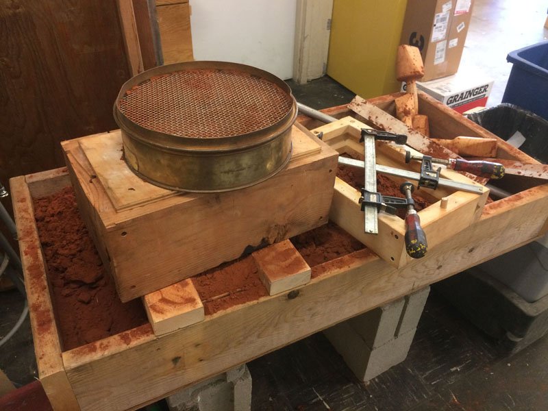
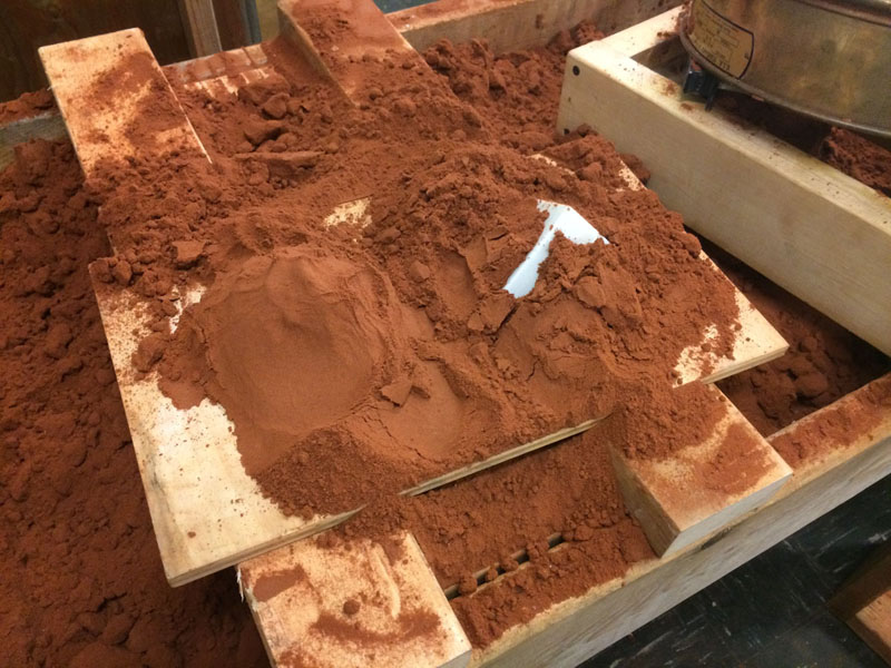
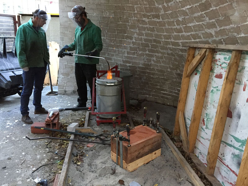
The architecture molding bench.
As with many disciplines, sand casting has its own vocabulary.
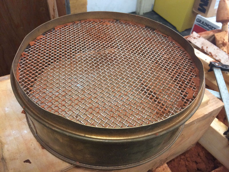
A riddle is used for screening molding sand to break up clumps and remove debris.
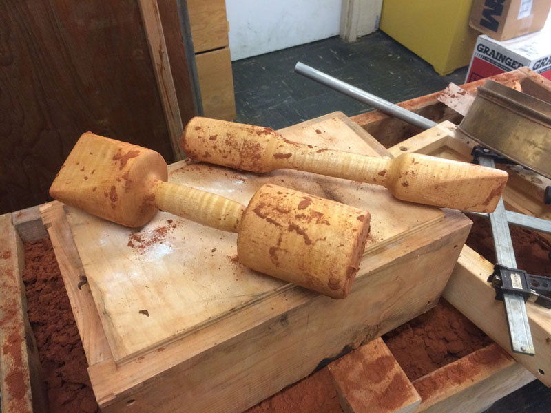
Rammers are used to compress the sand into the flask. The flask is the container the rammers are sitting on that holds the molding sand.
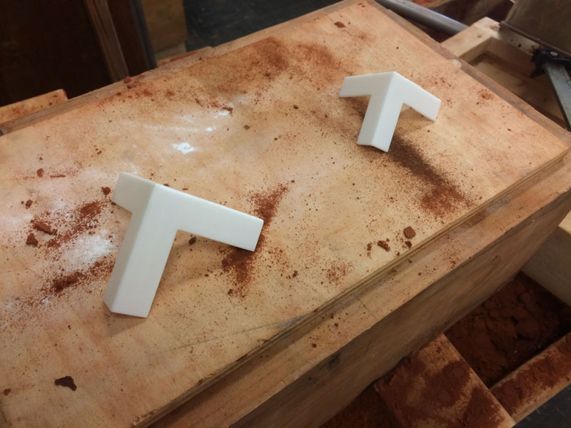
The object around which the mold cavity will be formed is called a pattern. A Google image search for foundry pattern will yield many other examples. The style of type of pattern produced will often be determined by intended volume of production, available equipment and materials, and other factors. This is a very basic 3d printed pattern, a choice made for expediency and flexibility. Having not cast this geometry before, I was not certain how I wanted to place it in the mold, and a basic 3d printed pattern gives the ability to try multiple molding strategies to figure out what works best.
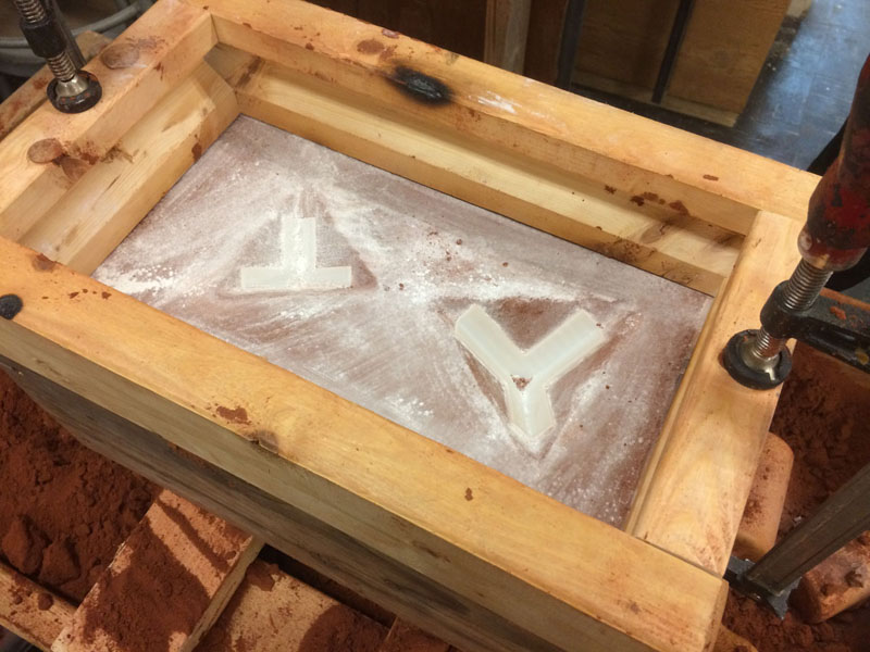
I want to cast these patterns in this orientation. The reason I have chosen this orientation is because I would like the inner and outer surfaces of this corner brace to be parallel, but I need to have draft in order to be able to remove the pattern from the sand. If I were to orient this part sitting on the flat plane defined by the outside face of two legs, with one leg oriented vertically, there would need to be ~5 degrees of taper on each vertical surface, which would change the pattern drastically. In this orientation, all the faces are at 45° angle relative to the parting line.
Because the first stage in producing the mold will be to ram sand down into the cope (top section of the flask), I needed to make a temporary base under the pattern. This base, a simple mound of molding sand that I compacted with my hand and pressed the pattern into, will do three things:
1. Support the pattern from being crushed during ramming
2. Help keep the pattern in position during ramming, and
3. Keep sand I am ramming into the cope from spilling underneath the pattern.
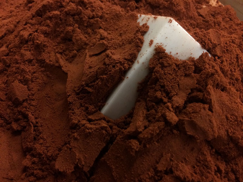
Once I compacted the mound of sand, I pressed the pattern down into it and further compacted molding sand around it.
This is a good opportunity to introduce the molding sand. We are using Petrobond, a so-called "oil bond sand" that is made from fine silica sand, clay, and mineral oil. The clay, wetted with oil, acts as a binder and gives the sand strength once it is compacted. The alternative to oil bonded sands are "green sands", which are formed from sand, clay, water, wood flour, and a few other ingredients. Oil sands are stronger, require less maintenance, and are generally easier to use, but are more expensive, and require petroleum products. Green sands are cheaper, and can be made DIY, but they require more maintenance, since the water will evaporate out. Too dry and they won't mold well, too wet and the steam formed when molten metal is poured into a mold will cause a variety of problems. In the context of an academic shop, the more forgiving oil sand makes more sense.
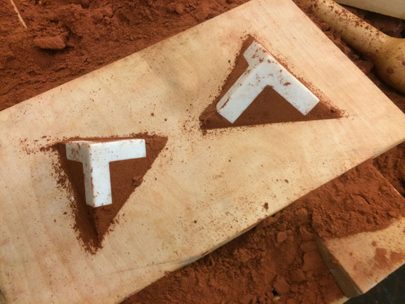
After compacting sand around my patterns to support them, I used a straight piece of scrap as a screed to remove the excess material. Here, the patterns are on the molding board, scraped clean.
The next step is to clamp the cope onto the molding board. The cope, once again, is the top half of the flask, which is the vessel that will contain the sand. You can see scorch marks on the top of the cope, from contact with molten aluminum during previous pours. This is the orientation that the flask will be in during the casting process.
Before ramming in sand, I add parting dust (in our shop this is baby powder), which will later help the pattern release from the sand, and will prevent the sand I am about to add from bonding with the pyramid of sand supporting the pattern.
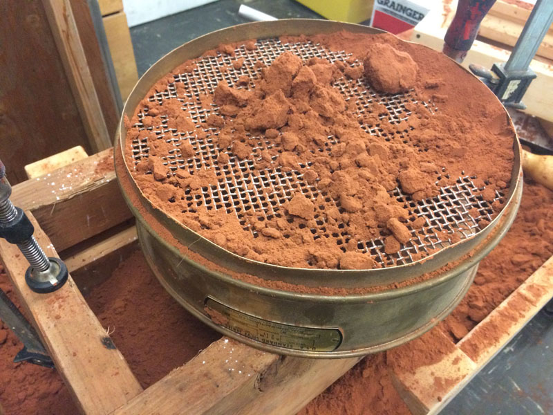
Here I am passing molding sand through the riddle to break up clumps and help find any debris, such a scraps of aluminum, tools like spoons, splinters, and other things that might have gotten mixed into the sand.
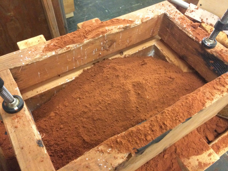
Screened sand in the cope, ready for ramming.
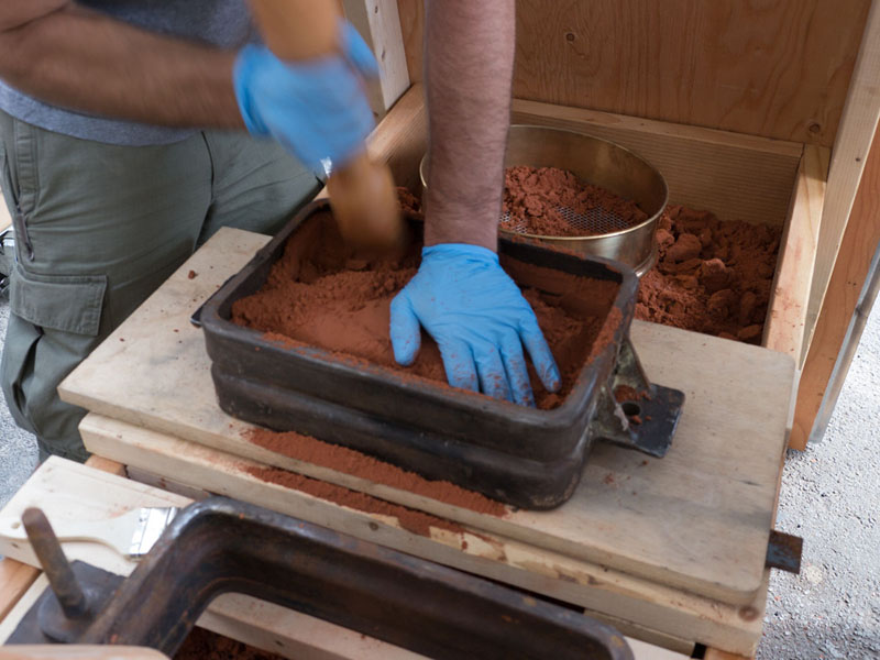
Using a rammer to compact molding sand into a (different) flask.
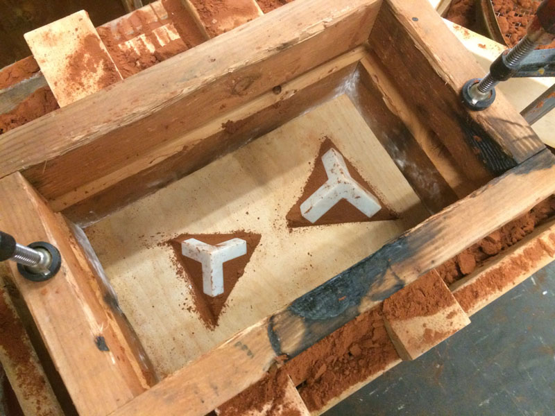
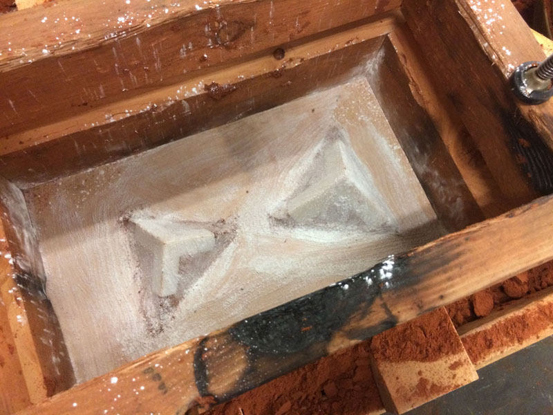
Skipping slightly ahead (I have a few holes in this documentation to fill in) we see the cope, now inverted, with the drag (bottom part of the flask) clamped on, and the pyramid of sand that was underneath the pattern to support it scooped out with a spoon. Fresh parting dust has also been applied.
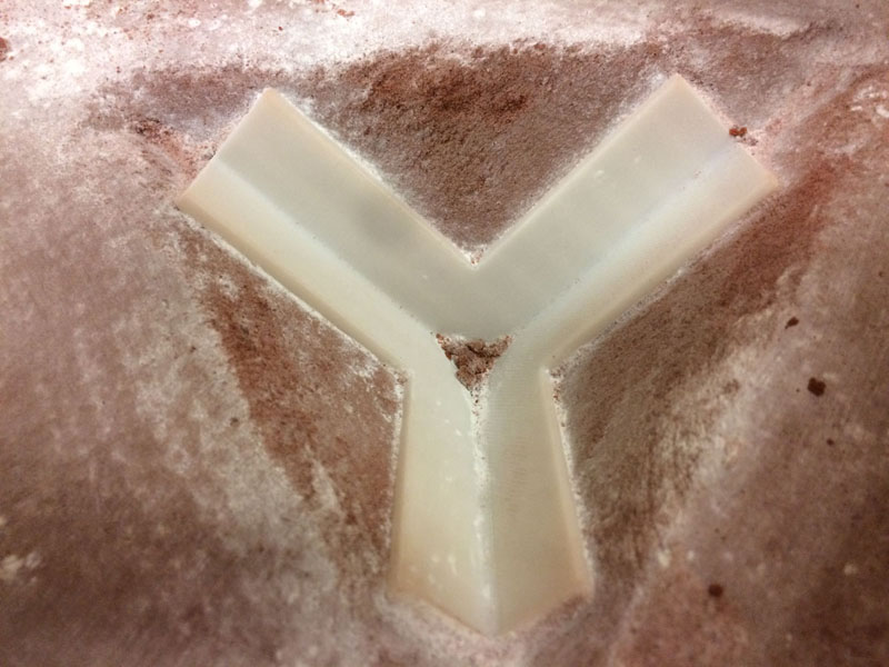
Detail of the pattern embedded in the cope. I cleaned out the loose bits of sand before ramming in the drag half of the mold.
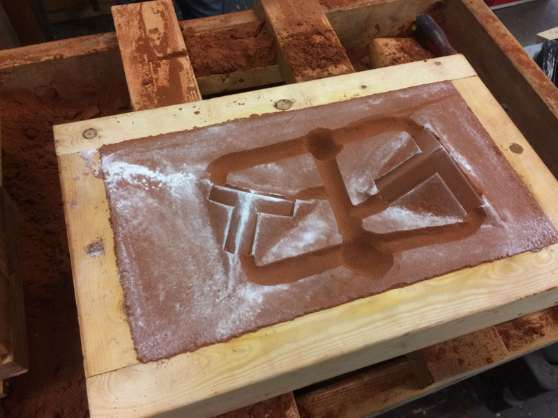
Skipping a few more steps ahead, this image shows the drag (bottom half of flask) after it has been separated from the cope. I have also manually dug in wells, runners, and gates. This was done with a spoon after separating the cope and drag. The wells are the deepest indentations. They are there to capture heavy inclusions, such as bits of sand that broke off the mold during the pouring process, and trap them so they do not get swept into the mold cavity. Runners are the horizontal channels leading towards the pattern itself, and gates are the actual openings that connect the pattern to the runners. I had no idea how this would turn out, so this was really a test. A future version of a pattern for this part would be machined on a flat plate, and would include geometry for the wells, runners, and gates. As I write this, my intention is to add that version to this tutorial once it is completed.
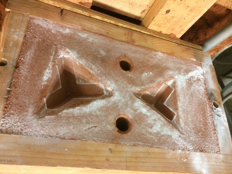
Skipping yet further ahead, the completed cope, with patterns now removed, and the sprue and a riser cut. The sprue is the hole that the metal is poured into. Not shown in this image is a cone I've dug out with a spoon on the other end of the sprue to make an easier target to pour into. The riser, opposite the sprue, is here to help keep the central spine of the casting hot. The goal is always to have the parts you are making solidify first, and the infrastructure of the mold cavity (gates, runners, wells, risers, sprue) solidify after. This is done so that if the part you are making shrinks enough as it cools to need extra metal to be drawn into the cavity, there is a reservoir of still-molten metal available to draw from.
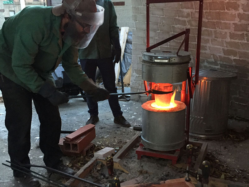
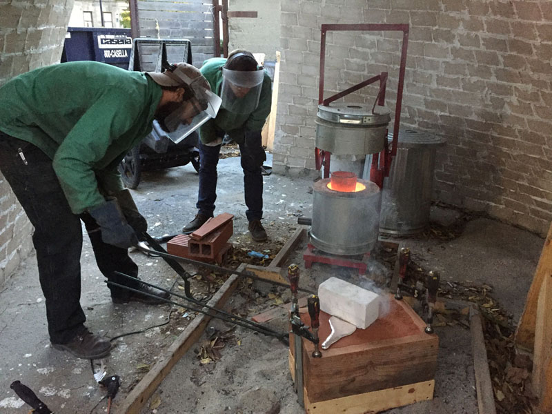
After some technical difficulties bringing the flask halves together, we have begun to melt the aluminum. The cone-shaped opening on the sprue is now visible on the flask. The furnace is ignited, a crucible (vessel that holds the molten metal) is inside with scrap aluminum, mostly melted, and I am measuring the temperature of the metal with a thermocouple. The aluminum melts around 660° C, and our target pouring temperature is around 750° C. Steps not shown include closing the flask, igniting the charcoal, and filling and placing the crucible. The hair dryer, pictured, serves as a blower to force a higher volume of air through the burning charcoal, to generate the energy needed to melt the aluminum. Depending on the temperature outside, the temperature of the furnace, and the volume of aluminum needed, it is sometimes required to refill the charcoal partway through the melt.
Here the aluminum has come up to the pouring temperature, and I use tongs to lift the crucible out of the furnace.
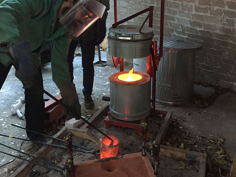
Here is use a homemade instrument to skim any unwanted debris off the surface of the molten aluminum. The goal is to remove all floating impurities at this point.
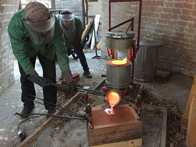
Pouring is complete, with a puddle of excess aluminum in the top of the sprue.
Here I cover the sprue with a fire brick. This is intended to help insulate the sprue, to encourage it to stay liquid until after the part has frozen.
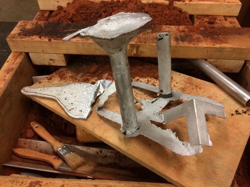
Here is the completed casting. The result is not perfect, but more successful than I expected. This is a small part, and was cooling for around 30 minutes before I opened the flask, which is just enough time to clean up the tools around the furnace outside. Larger castings need longer cooling times.
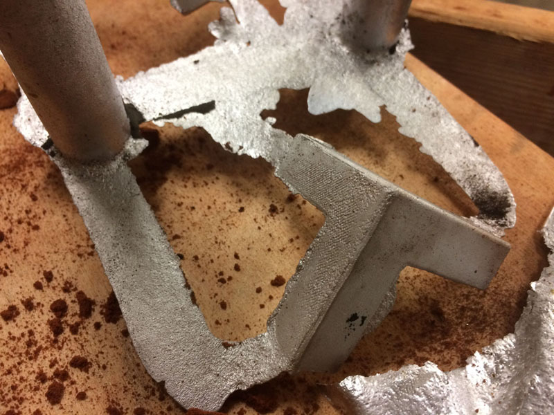
The sand resolves finer details than the texture of an FDM print. Here you can see the rougher side of this part, where the raft from the printing process was peeled off. I will sand the pattern more if I want to make any finished parts with it, but this was just a test.
This tutorial has many holes still, and missing images, but hopefully I will run through this again soon and start to fill in some of the missing information.