Week 12: Networking & Communications
This week we were tasked to design and build a wired &/or wireless network connecting at least 2 processors. I chose to create the serial bus system. Serial communication sends data one bit at a time in a sequential manner.
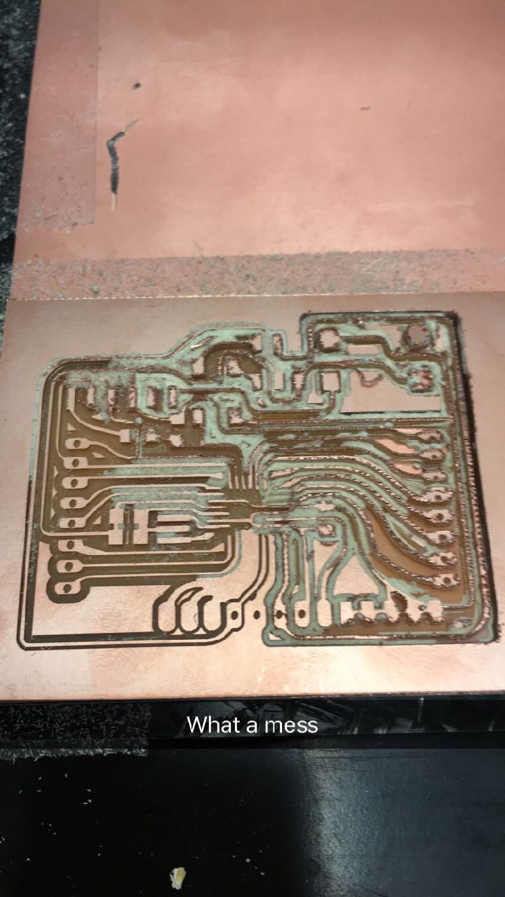
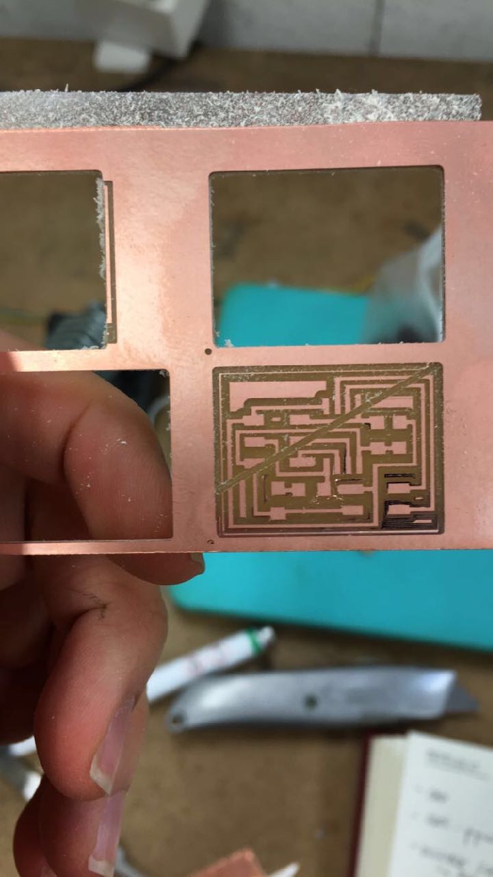
I also spent this week heavily investing in trying to get more dexterous with electronics, recreating the fabduino. I had a lot of help from the wonderful Raphael Schaad and Hunmin Koh, both who were incredibly patient and answered many basic questions that I was rather insecure about. Unfortunately, the mill in the architecture section had several problems that substantially lengthened out cutting time. A few learnings to get a good cut with the mill:
1. The mill board should be flat and not bent. When removing PCBs it causes the board to be bent upwards, creating an undesirable bend
2. The mill should be lowered to some point, then using the hex modela key released to lightly touch the pcb bed
3. Cursory and quick ways to tell your board isn't sitting flat: Cutting noise becomes louder, more or less dust on the mill coming out
4. Taping ethics: Even an additional piece of tape can cause unevenness on the board, bubbles as well
5. Make sure the terminal is open. If the mill stops responding, restart terminal and the mods again
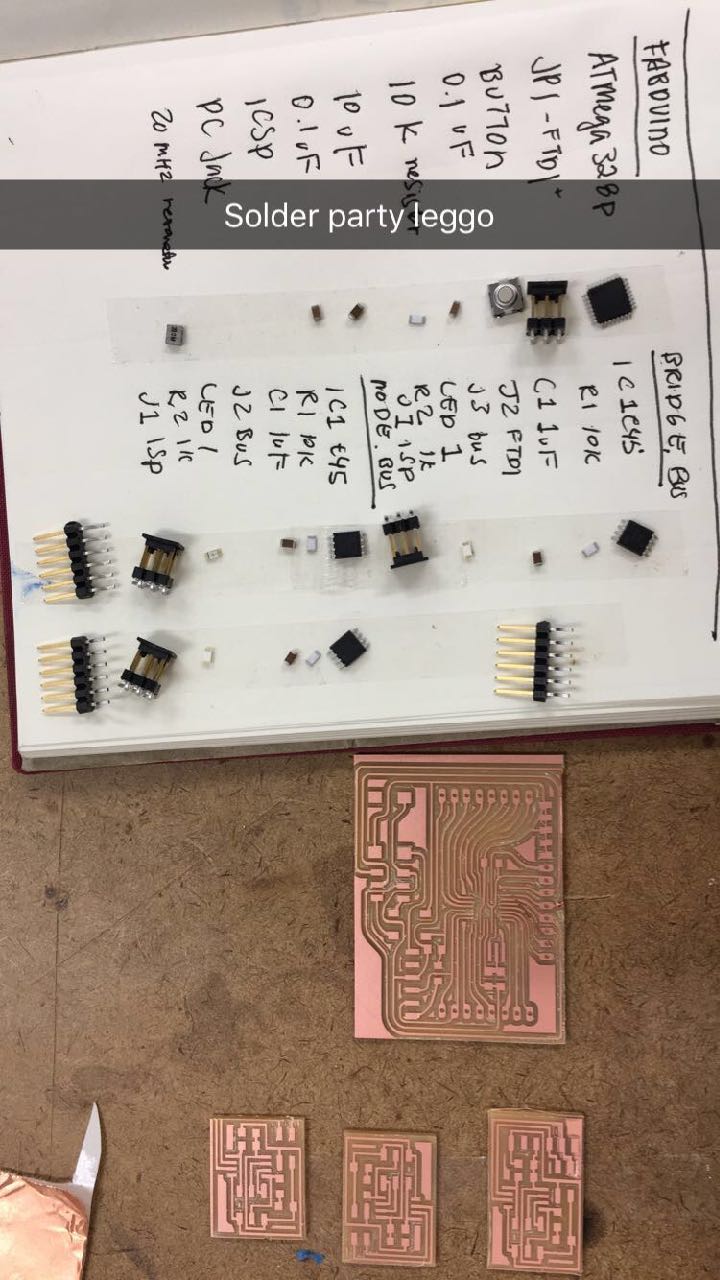
After I was able to get my boards to be cut, I proceeded to solder them. This week I got more familiar with using the voltage meter as well. Here are my lessons on mitigating shorts on the board:
1. The solder should be shiny and not muted. Some of the black debris coming from headers can also cause shorts
2. The voltage meter tests for connectivity between circuits. Comparing the schematic, one applies the 2 prongs on wires that ought to be connected. We also test for places that are connected, but shouldn't be
3. Using alcohol to clean up the board before soldering can be effective
4. Being process driven with the voltage meter is helpful. Check for shorts one step at a time. Don't stuff the whole board and work backwards, which makes it difficult to isolate what is causing the short
5. LEDs have polarity: The green strip is the negative, cathode (C) side, and the latter is the positive, anode (A) side.Reversing this made my board finally work
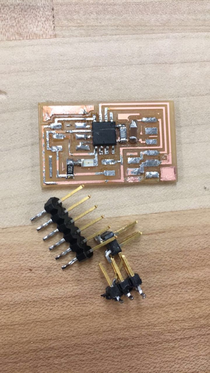
This is the beautiful fabduino designed by Raphael Schaad, which is an alternative to an arduinoIDE. I forgot to mill out the holes so Hunmin helped me manually drill holes in. A lot of surgery was done.
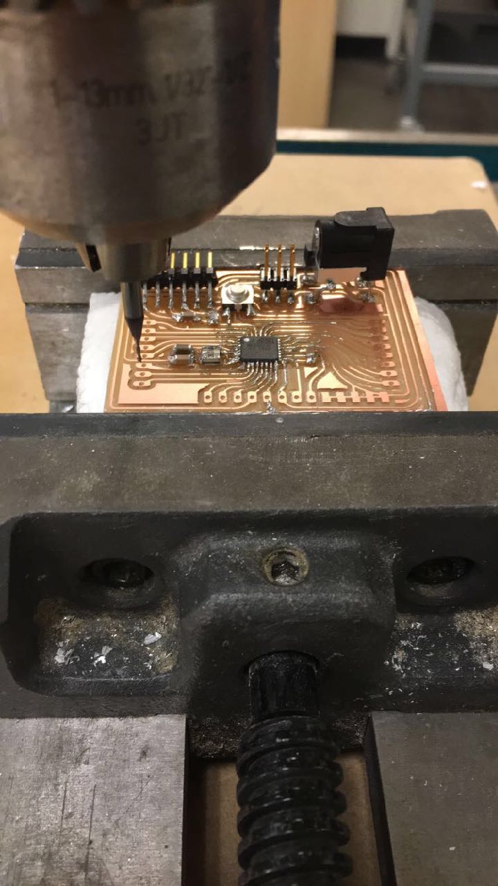
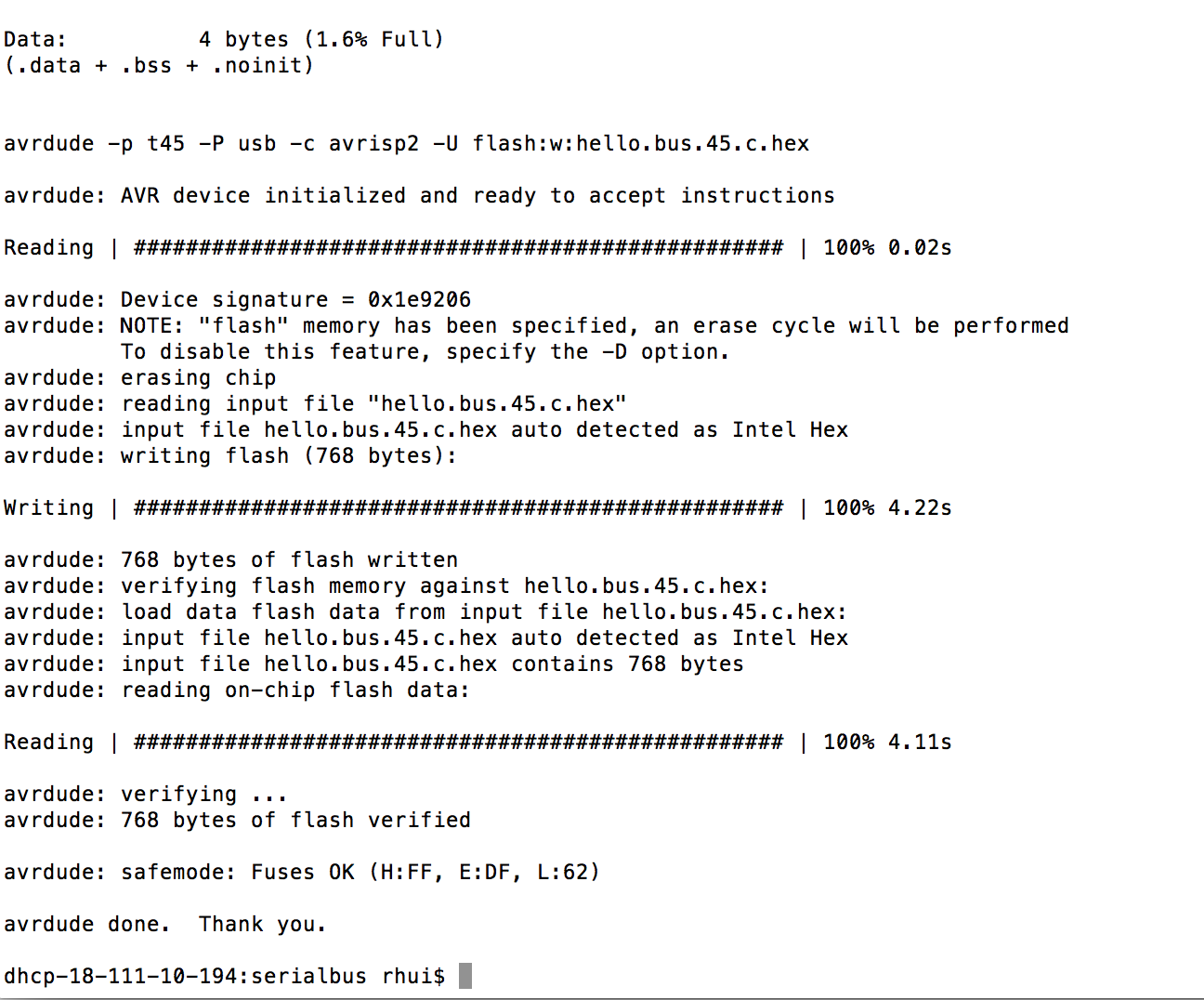
After I was able to create my boards, I programmed them using the AVRISPII since my programmer had broken recently. Using neil's hello.bus.45.c code, I programmed my board in ubuntu using the sudo -f make hello.bus.45.make program-avrisp2 line. One has to go into the code and change the node ID to '0' (first for the bridge), and '1', '2', subsequently for every node
The first few times there was the connection -f failure response, which made me go back to the board to troubleshoot. The first mistake was stuffing two 1 K resistors rather htan 1 10-K resistor and another 1-K resistor.
Another thing that was peculiar was that the program can upload, but the board won't blink. This made me realize that the LEDs were reversed
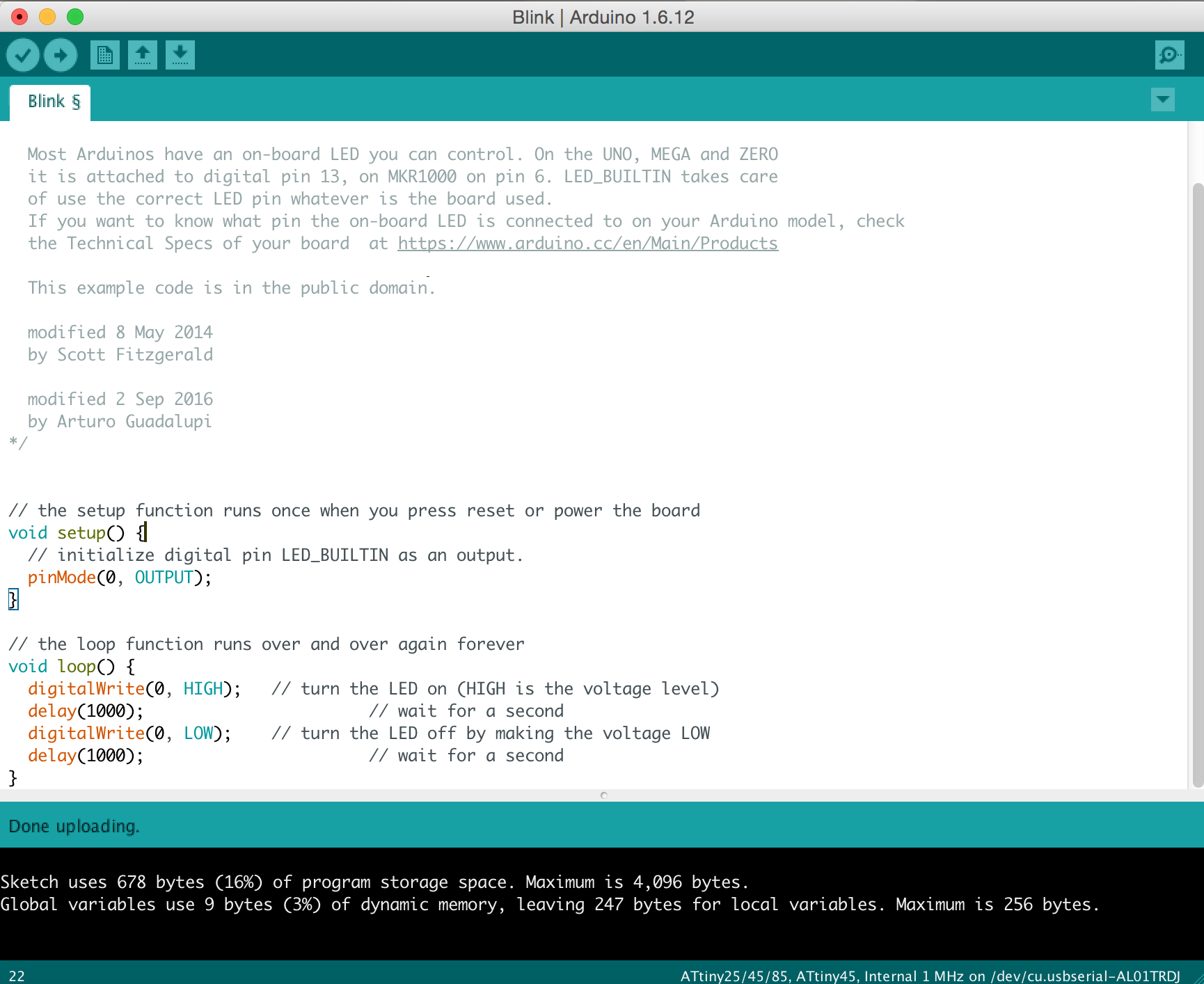
Since it still wouldn't blink and I didn't have time to narrow it down as to why, I decided to try and reprogram it in arduino IDE using a blinking code. It worked, and my programs started blinking. But this doesn't mean that they were networking
I have to go back and finish this last step