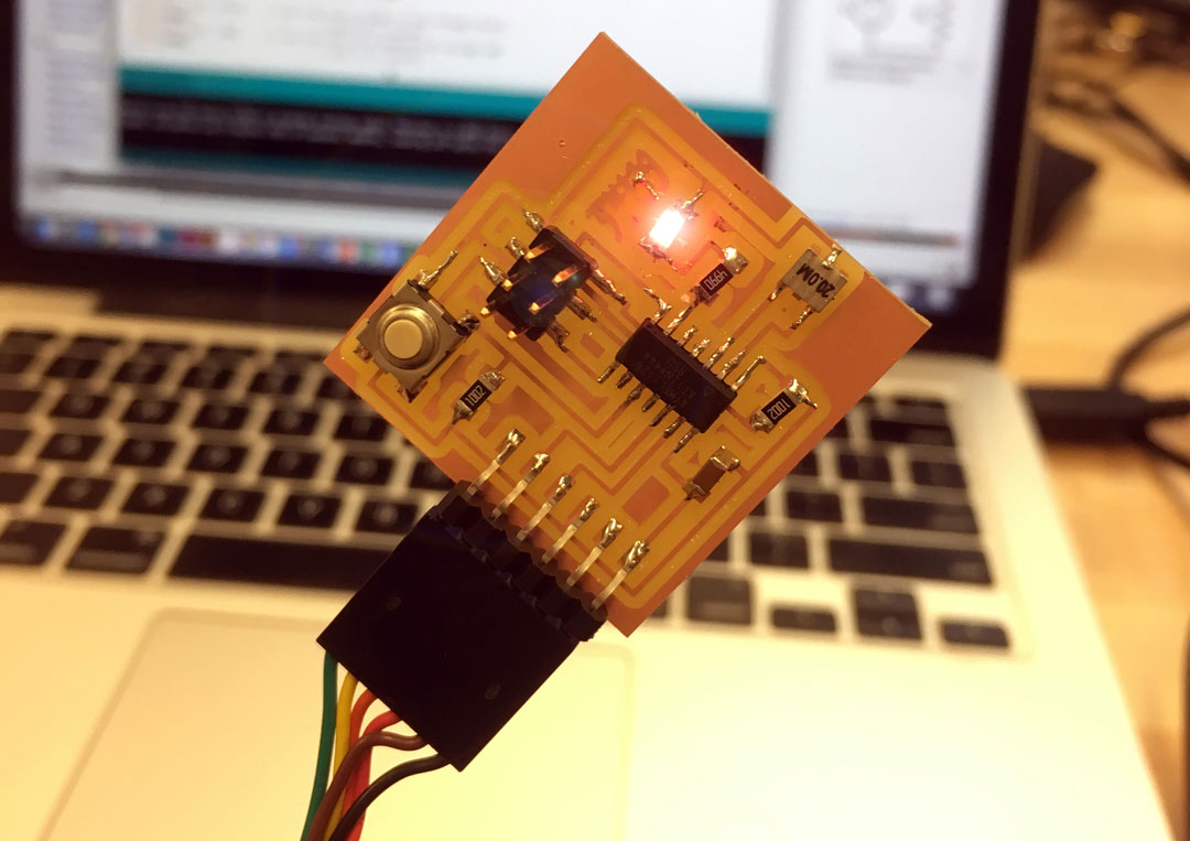
This week was especially exciting - after milling, soldering, programing, connecting the board to the Programmer- and that LED shined bright. It is a thrilling to play with the code and see how the LED reacts - from information to material. I also started to further plan the electronics for my final project, looking for different kinds of vibrating motors, RF transmitters and distance measuring sensors. The less thrilling part of this week, although obviously crucial to future progress, is digging into the microcontroller and its various pins. The microcontoller is totally new for me, and its hard to wrap my head around the architecture of the pins, and even more, the binary to control the pins.
Trying to understand the ATTINY44
After looking for an intro, before going straight to the DATASHEET, found this good lecture, going through the basics of the ATTINY and a few tricks in C:
I’ve learned a few important conceptual stuff:
- A micro controller is a whole computer on a chip:
- You can write in various languages: C, Assembly, Basic
- CPU (1-20MHz)
- Dynamic memory (SRAM)
- Non-Volatile memory (FLASH)
But its a really basic computer;
Not much memory, no OS, Low level input/output
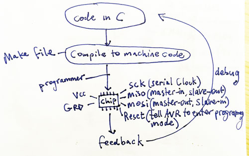
Programming any AVR microcontroller six wires are needed. Three of these wires are referred to as the Serial Peripheral
Interface (SPI) and are the Master In - Slave Out (MISO), Master Out - Slave In (MOSI), and Serial ClocK (SCK).
The "Master" is the ISP or the device you are using to program the AVR chip. The "Slave" is the AVR chip being
programmed. The other three wires are for the 5V power supply (VCC), Ground (GND), and Reset (RESET).
The SCK pin is where the Master provides the clock information for communication. Every pulse of the SCK pin sends
one bit of data over both the MOSI and MISO pins (this is essentially the ATtiny and programmer back and forth).
The GND pins of both the programmer and AVR should be connected to help the chips establish the same reference voltage.
The RESET pin is the channel to which the programmer is able to erase the contents on the AVR chip and enable serial
programming. The VCC pin is connected to remove the need for batteries or external power supplies.
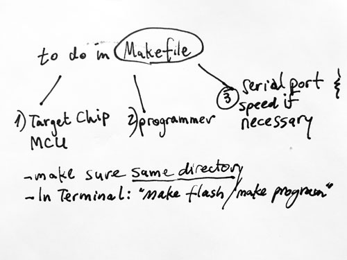
Workflow
Makefile
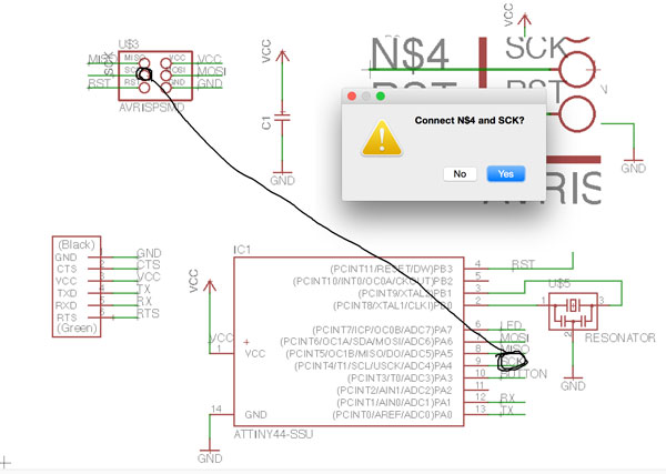
First steps in programming my Button+Led board
At first, after trying to connect my board to the programmers and to power, found out its dead. After investigation, it turned out the routing was missing a trail! this was caused by a misconceptions the Eagle scheme. Named the pins, but to of then (SCK) did not recognize each other. Had to re-label and re-name them for them to identify each other and link in the scheme.
So, re milled, re soldered…
Then connected the whole system again. and opened Arduino IDE.
Arduino IDE
Decided using Arduino Software for programming my board because I have found a few libraries that will help me in my final project. Followed this guide to set up my IDE Arduino environment for the first time: http://highlowtech.org/?p=1695
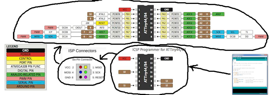
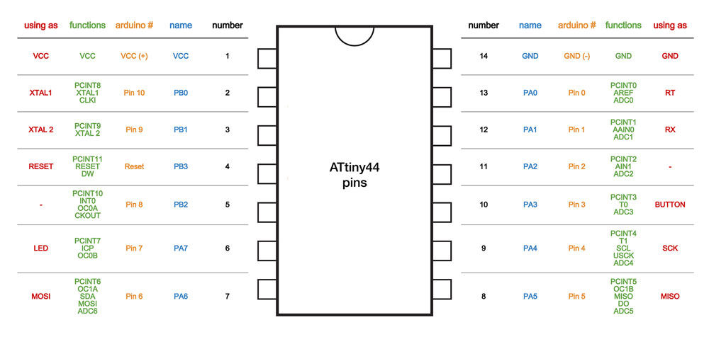
The pin number that Arduino knows for the ATtiny are different from the pin numbers in the datasheet. I used this map to enter the correct number of pins in Arduino software:
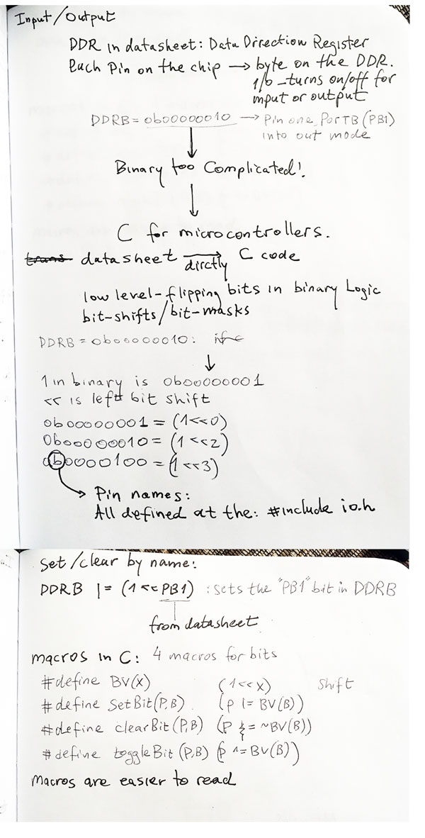
Some note on C and ATTINY peripherals