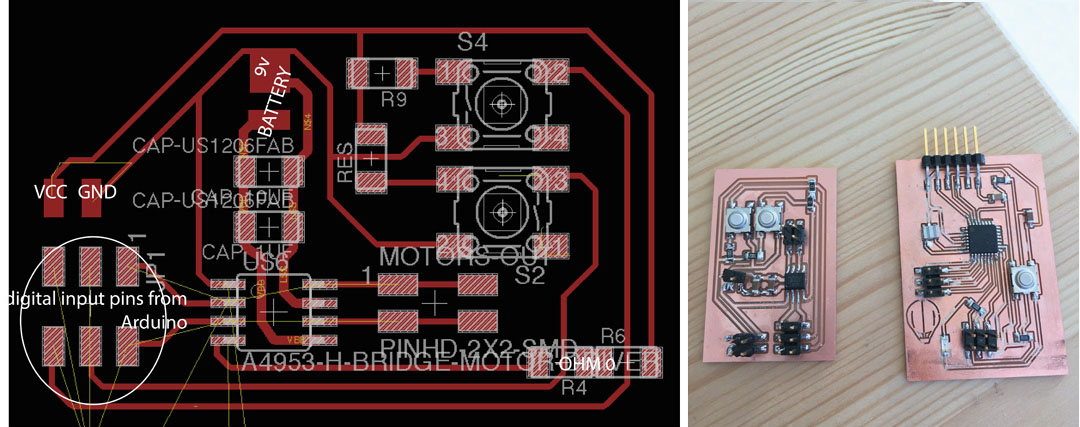
Fabduino
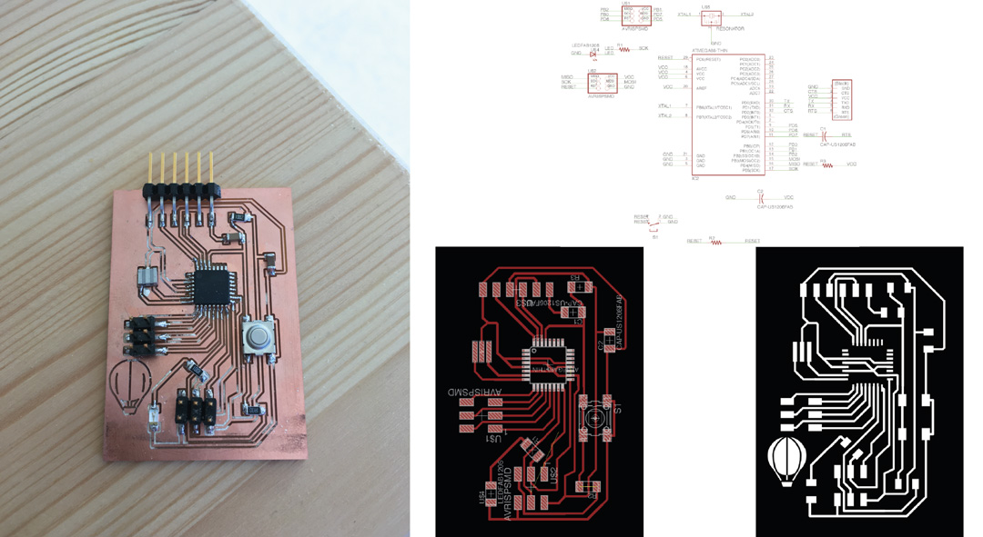
I decided to make the Fabduino to avoid remaking the whole board with every test.
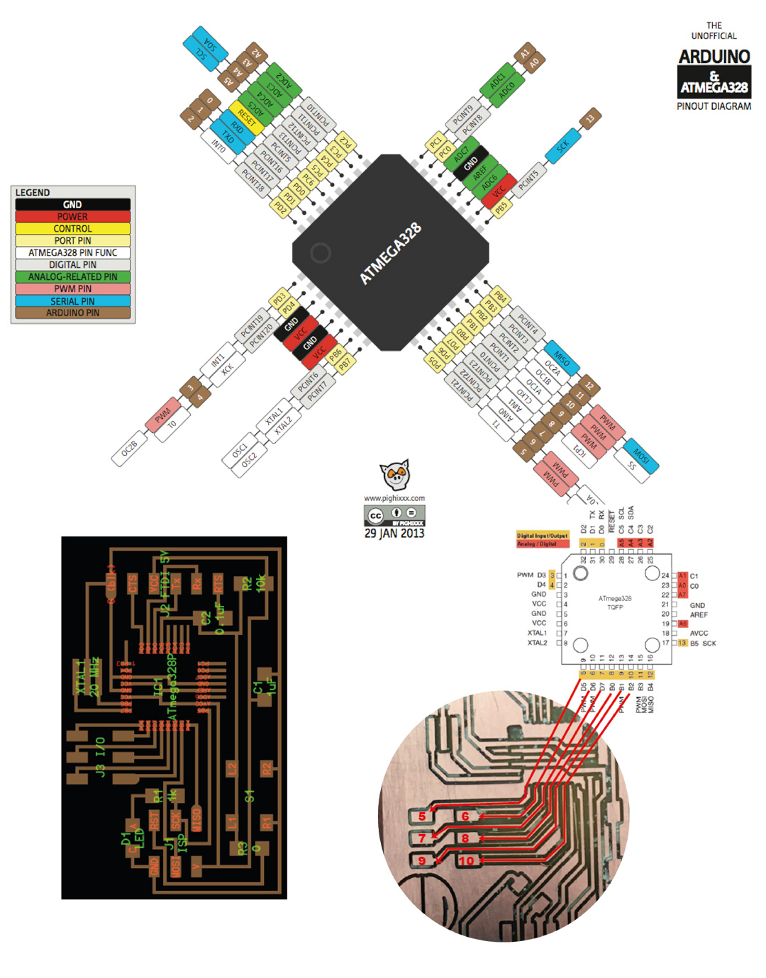
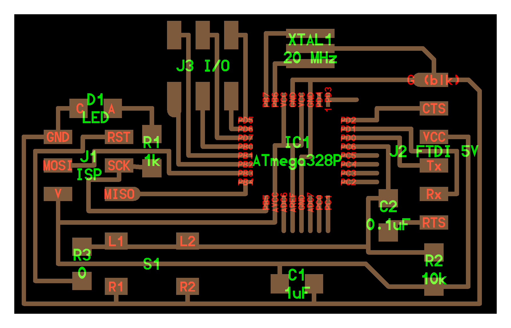
The Xmega 328P has more digital and analog pins, that can be connected to an additional board.
This schematic has 6 pins free, all digital.
The hello arduino board: http://academy.cba.mit.edu/classes/embedded_programming/hello.arduino.328P.png
The H-Bridge
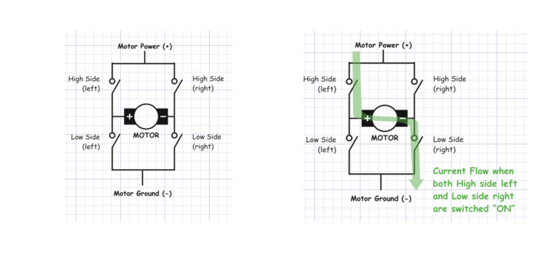
Sometimes called a "full bridge" the H-bridge is so named because it has four switching elements
at the "corners" of the H and the motor forms the cross bar. The basic bridge is shown in the figure to
the right.
The key fact to note is that there are, in theory, four switching elements within the bridge.
These four elements are often called, high side left, high side right, low side right, and low side
left (when traversing in clockwise order).
The switches are turned on in pairs, either high left and lower right, or lower left and high right,
but never both switches on the same "side" of the bridge. If both switches on one side of a bridge are
turned on it creates a short circuit between the battery plus and battery minus terminals.
This phenomena is called shoot through in the Switch-Mode Power Supply (SMPS) literature.
If the bridge is sufficiently powerful it will absorb that load and your batteries will simply
drain quickly. Usually however the switches in question melt.
To power the motor, you turn on two switches that are diagonally opposed. In the picture to the right,
imagine that the high side left and low side right switches are turned on. The current flow is shown in
green.
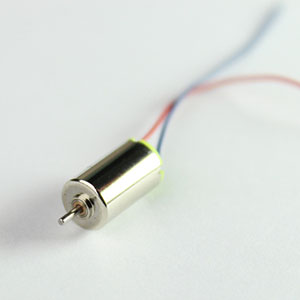
Mini dc-Motor + Buttons (forward / backwards)
Working Principle Of A DC Motor
A motor is an electrical machine which converts electrical energy into mechanical energy.
The principle of working of a DC motor is that "whenever a current carrying conductor is placed in a magnetic field, it experiences a mechanical force".
The direction of this force is given by Fleming's left hand rule and it's magnitude is given by F = BIL.
Where, B = magnetic flux density, I = current and L = length of the conductor within the magnetic field.
Fleming's left hand rule: If we stretch the first finger, second finger and thumb of our left hand to be perpendicular to
each other AND direction of magnetic field is represented by the first finger, direction of the current is represented by second finger then the thumb
represents the direction of the force experienced by the current carrying conductor.
Above animation helps in understanding the working principle of a DC motor. When armature windings are connected to a DC supply, current sets up in the winding. Magnetic field may be provided by field winding (electromagnetism) or by using permanent magnets. In this case, current carrying armature conductors experience force due to the magnetic field, according to the principle stated above.
Commutator is made segmented to achieve unidirectional torque. Otherwise, the direction of force would have reversed every time when the direction of movement of conductor is reversed the magnetic field.
This is how a DC motor works!
Code:
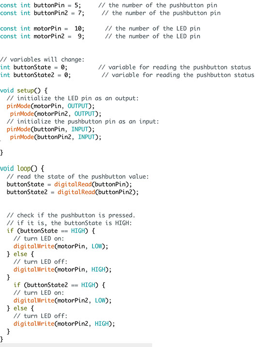
dc_motor_button code
hello_arduino_motors.brd
hello_arduino_motors.sch
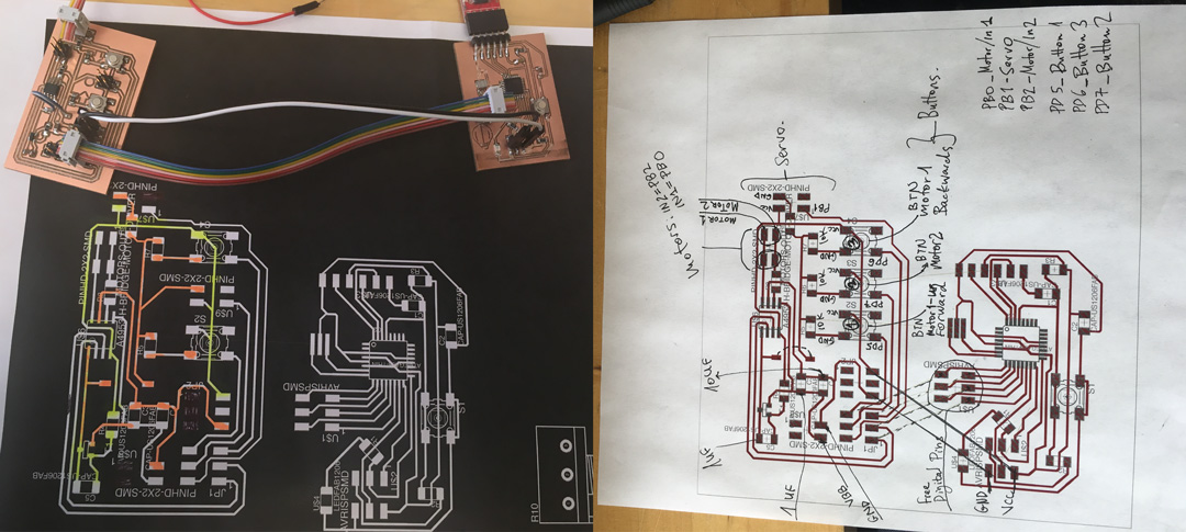
DC-Motor + Buttons + Servo + Potentiometer (FAIL)
Trying to go further, adding a servo with potentiometer to the motors, I mis-routed the board to connect Ground to Power in some point.
I also added a 5V regulator to the schematic, which turned out to be a mistake.
If the motors and the battery sit separately from the Xmega, there is no reason to add a regulator.