Some of this is duplicate information from Week 06 - Embedded Programming, and Week 08 - Input Devices so if you're looking for more detailed information about those processes, please take a visit to those pages.
"Hello World" Temperature Board
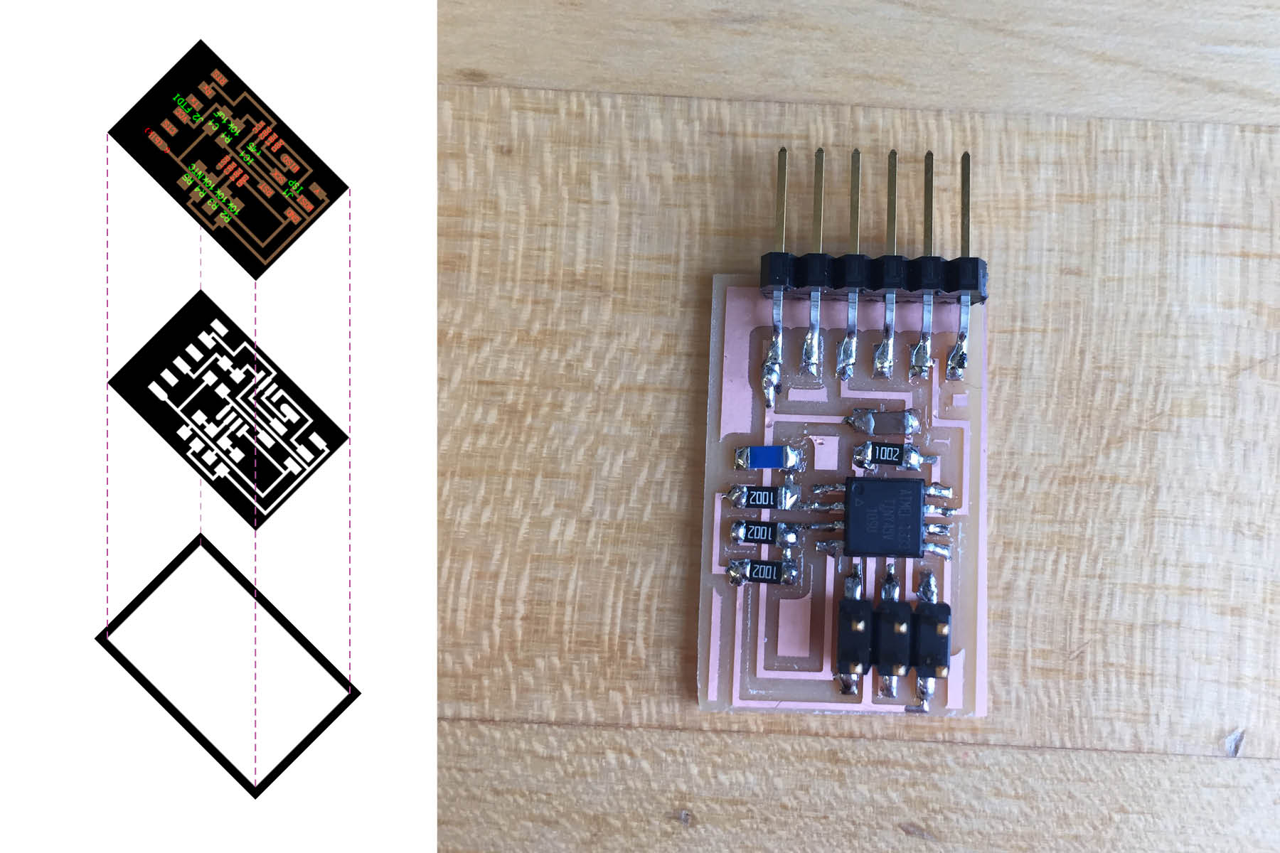
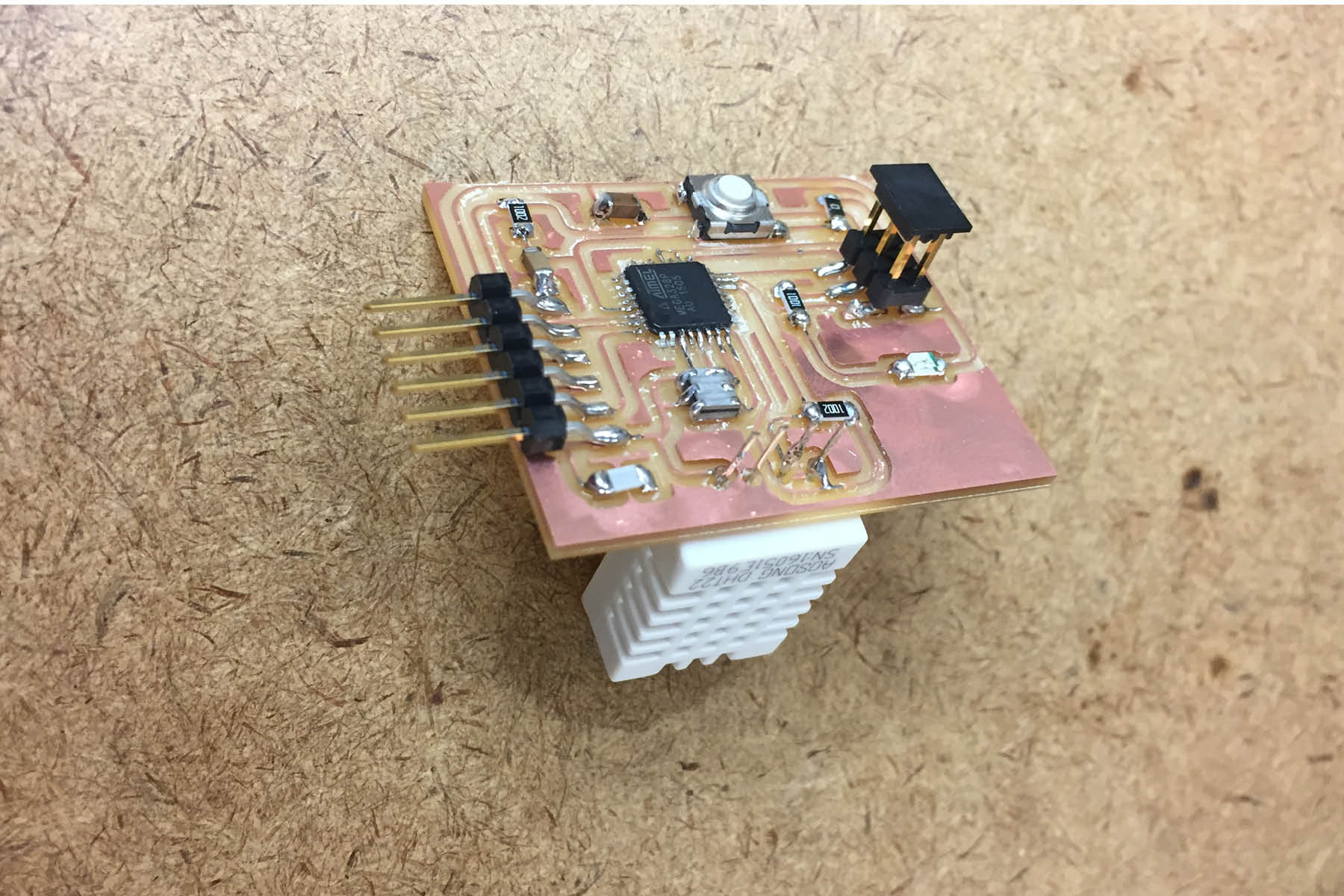
A few weeks ago I built Neil's "hello world" temperature board, and I only just this week realized that I used the wrong temperature sensor. I used the blue sensor from the drawer "temp. chip".
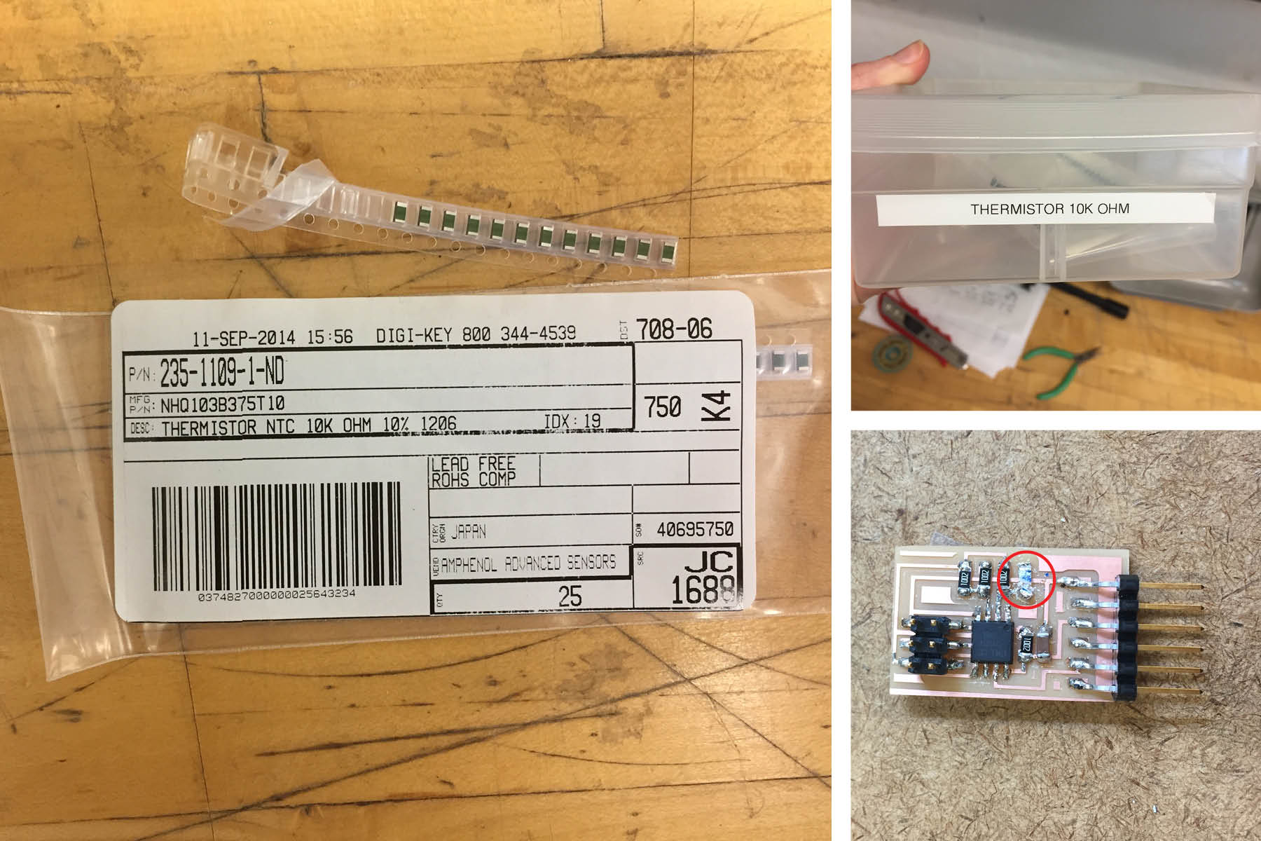
I found the drawer for the "Thermistor 10K ohm". It's green like the one in Neil's photo. I tried to delicately remove the blue one from the board and unfortunately I ripped teh copper spots up from where it was sitting. What started out as a simple 5 minute project turned into a 90 minute project as I had to remake the board and resolder all the parts.
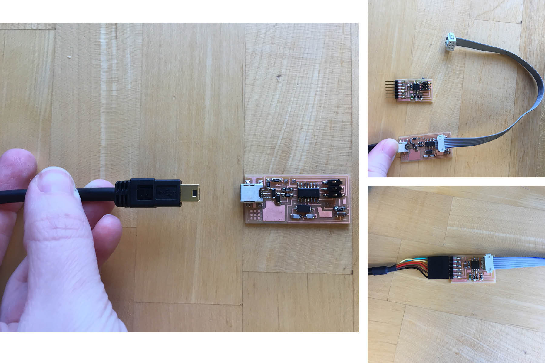
Step One: Plug the programmer into the computer with a mini USB cable.
Step Two: Plug the temperature board into the programmer using the ribbon cable. ORIENTATION MATTERS. I spent quite a while trying to program by board with the plug facing the wrong direction. This is a dumb mistake that can be easily avoided. The image at the top of the page shows what it SHOULD look like.
Step Three: once you've programmed your board, you can plug in the serial cable into the board and back into your computer.
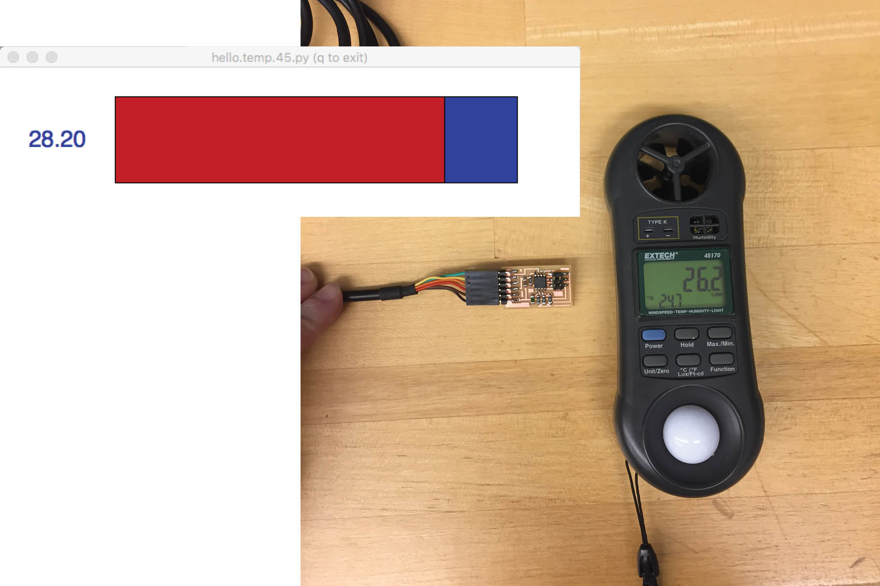
And here it is with the python program running.
However, it doesn't seem to be taking the same measurements as my storebought temp/humidty measuring device. (The Device reads 26.2% RH and 24.7C, so my python script is off by 3.5C). This means that I'll need to spend a bit of time calibrating the program.
Commands in Terminal
Navigate to the folder: $ cd ~/Desktop/files
Program the board: $ sudo make -f hello.temp.45.make program-usbtiny
Identify your serial cable: $ ls /dev/tty.usb*
Run the python script: $ python hello.temp.45.py /dev/tty.usbserial-A904NKJC
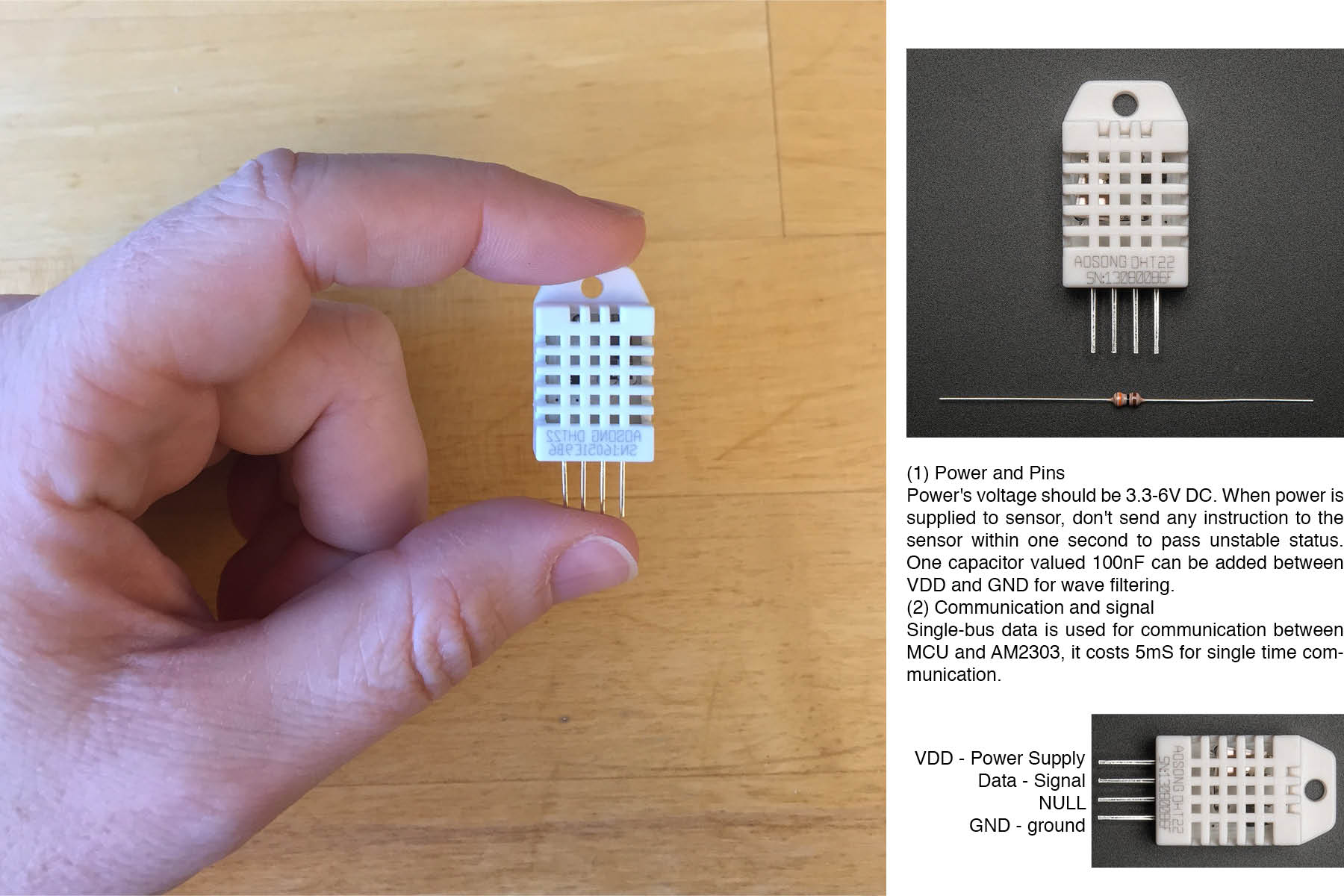
DHT22 Temperature and Humidity Sensor (from Adafruit)
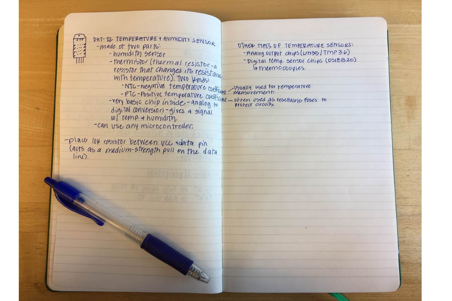
The data sheet for this sensor was much more straightforward than the ATtiny data sheet... except for all the Japanese.
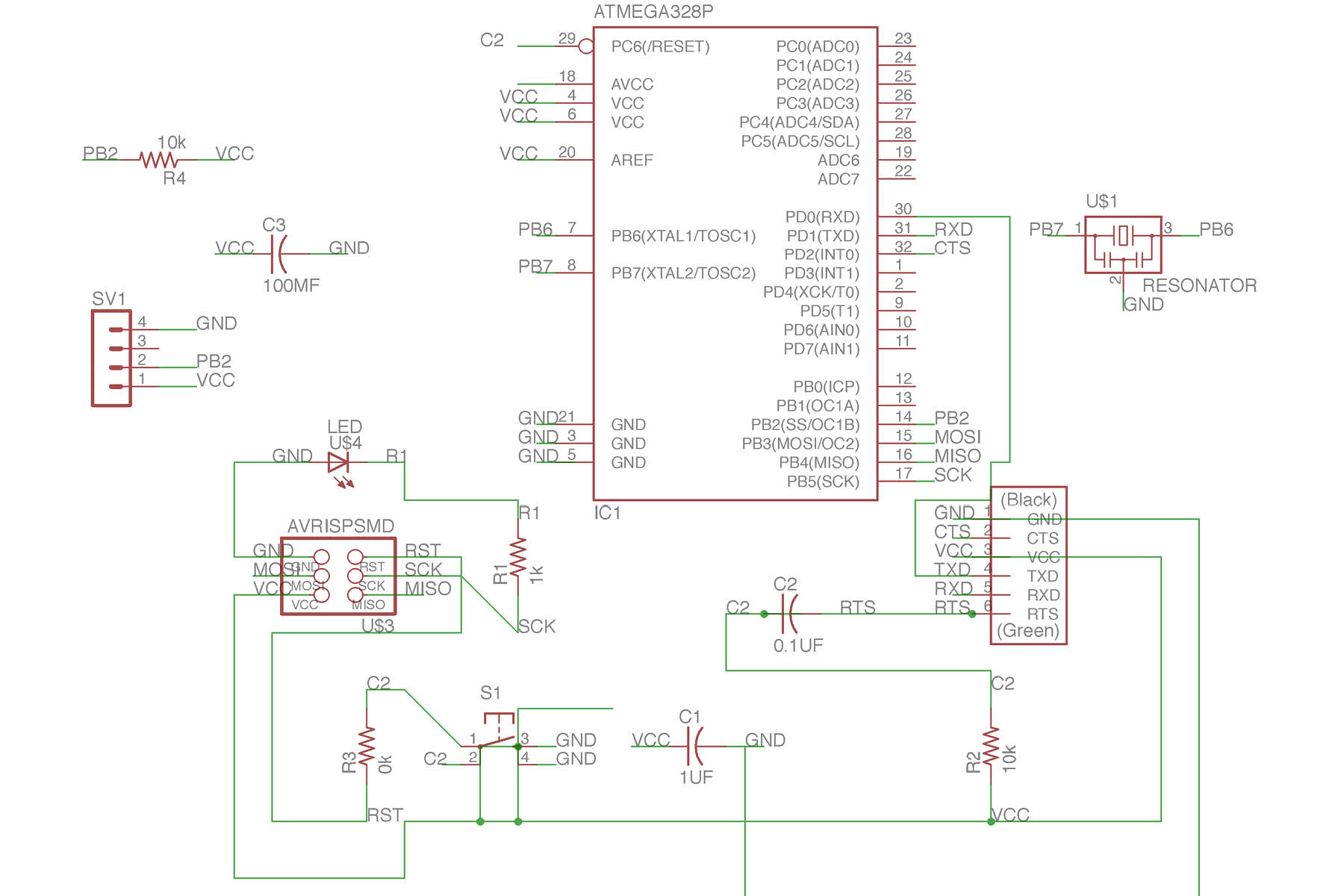
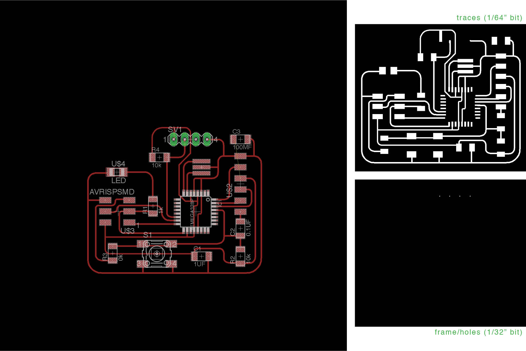
Here's the schematic from Eagle.
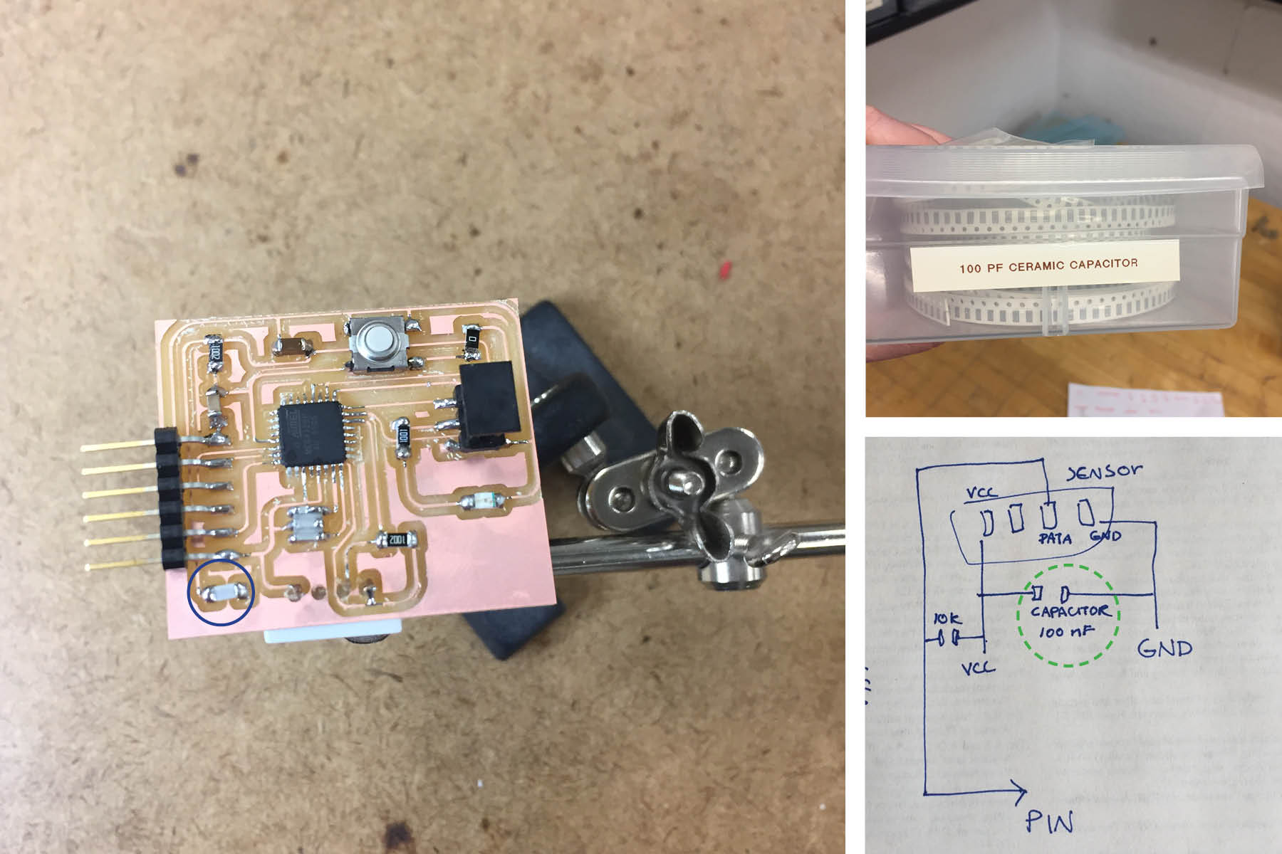
When meeting with the TA, she drew this little sketch for me so I could add it to Neil's Hello.Arduino board from the embedded programming week. I need to follow up on the "100 MF capacitor". I assumed it was 100 UF, but I could only find 100 PF. I'm not really sure what any of it really means, so I don't know if I've installed the correct piece.
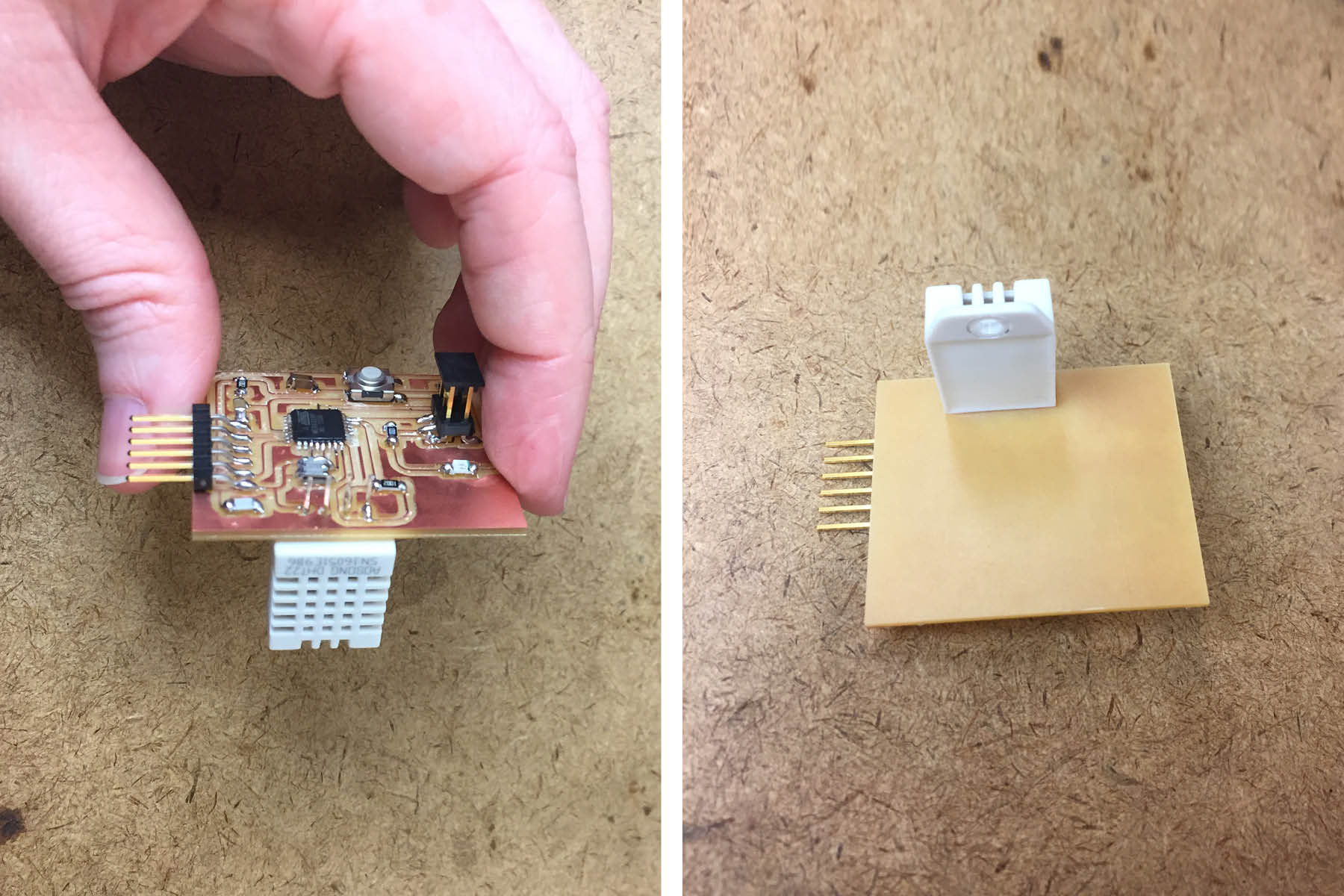
Soldering this on was easier than I thought. Now I need to figure out how I'm going to use it in my environment box before I decide if I'm going to use the wires or not. As a side note, I had to rotate the sensor in order to keep it with the correct paths.