HOW TO MAKE [ALMOST] ANYTHING_MAS.863
Week 04 - Electronics Design
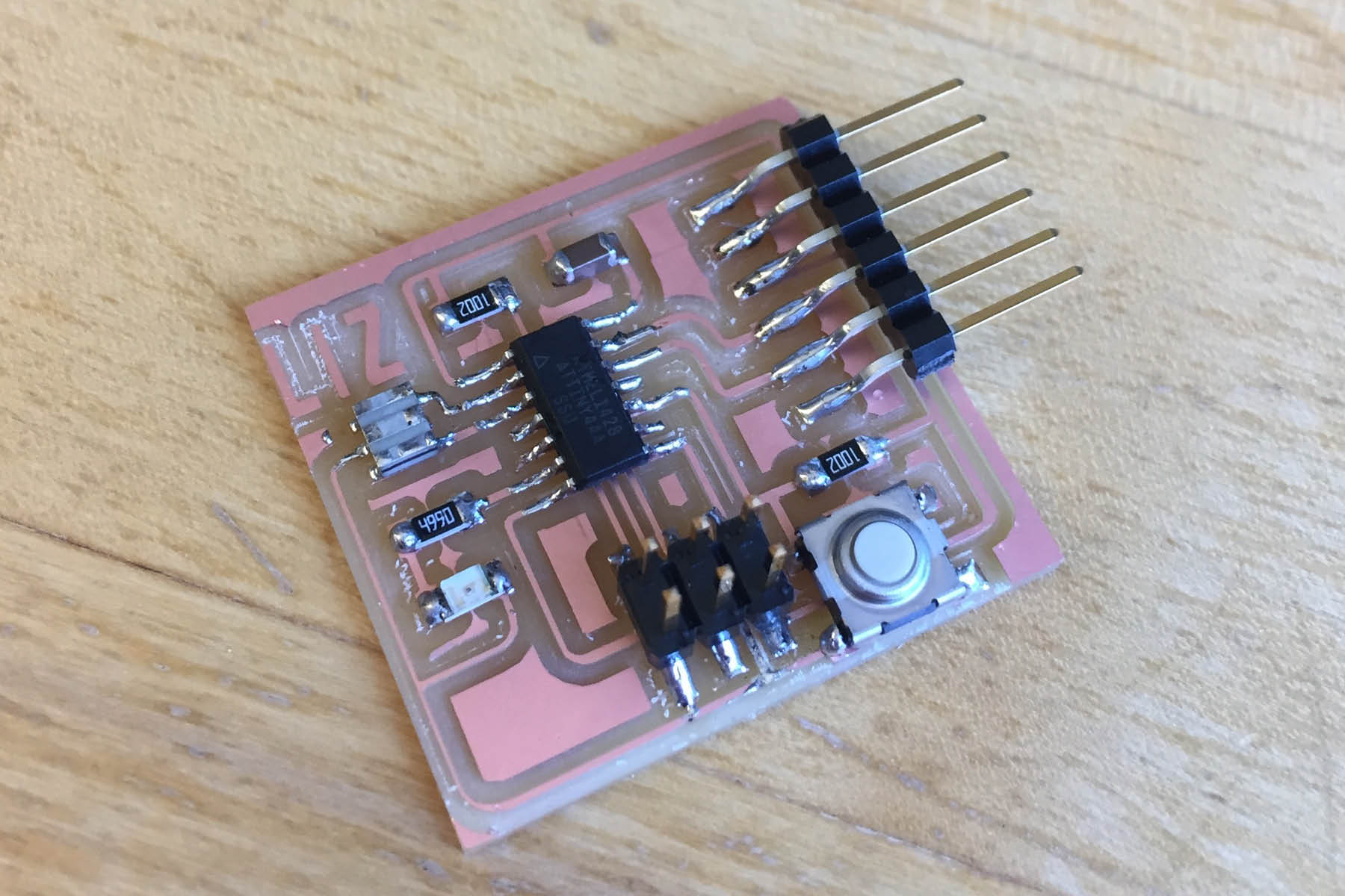
This weeks assignment was to redraw the echo hello-world board and add a button and LED (with current-limiting resistor). Still without much knowledge in electronics, this was more compliated than it sounds.

After installing Eagle and the fab library, I began adding parts into the schematic based on the instructions from the tutorial. From the class tutorial sheet:
A schematic in electronics is a drawing representing a circuit. It uses symbols to represent real-world electronic components. The most basic symbol is a simple conductor (traces), shown simply as a line. If wires connect in a diagram, they are shown with a dot at the intersection.
Also, at the top left of the image, there are a few stray wires. I noticed I had two wires that looked like they were properly connected, but actually weren't. I'm not sure why that happened but I only figured it out when I tried to draw the traces. When I went back to the schmatic and moved the resonator, the wires did not follow. I simply redrew them and was fine.
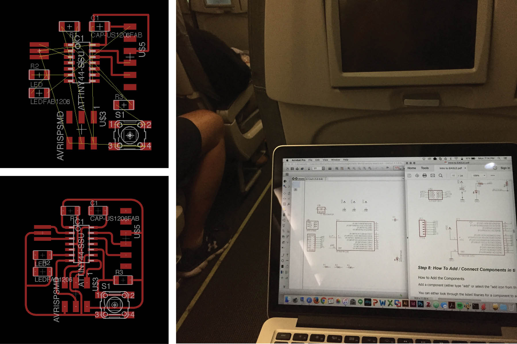
Lesson learned - do not do electronics work on the plane, it makes people uncomfortable and the flight attendant will ask you to stop.
Regardless, after adding all the parts and making connections on the schematic layout, the next step is to draw the traces on the board - the board layout shows how the electrical components and traces will be laid out on the board.
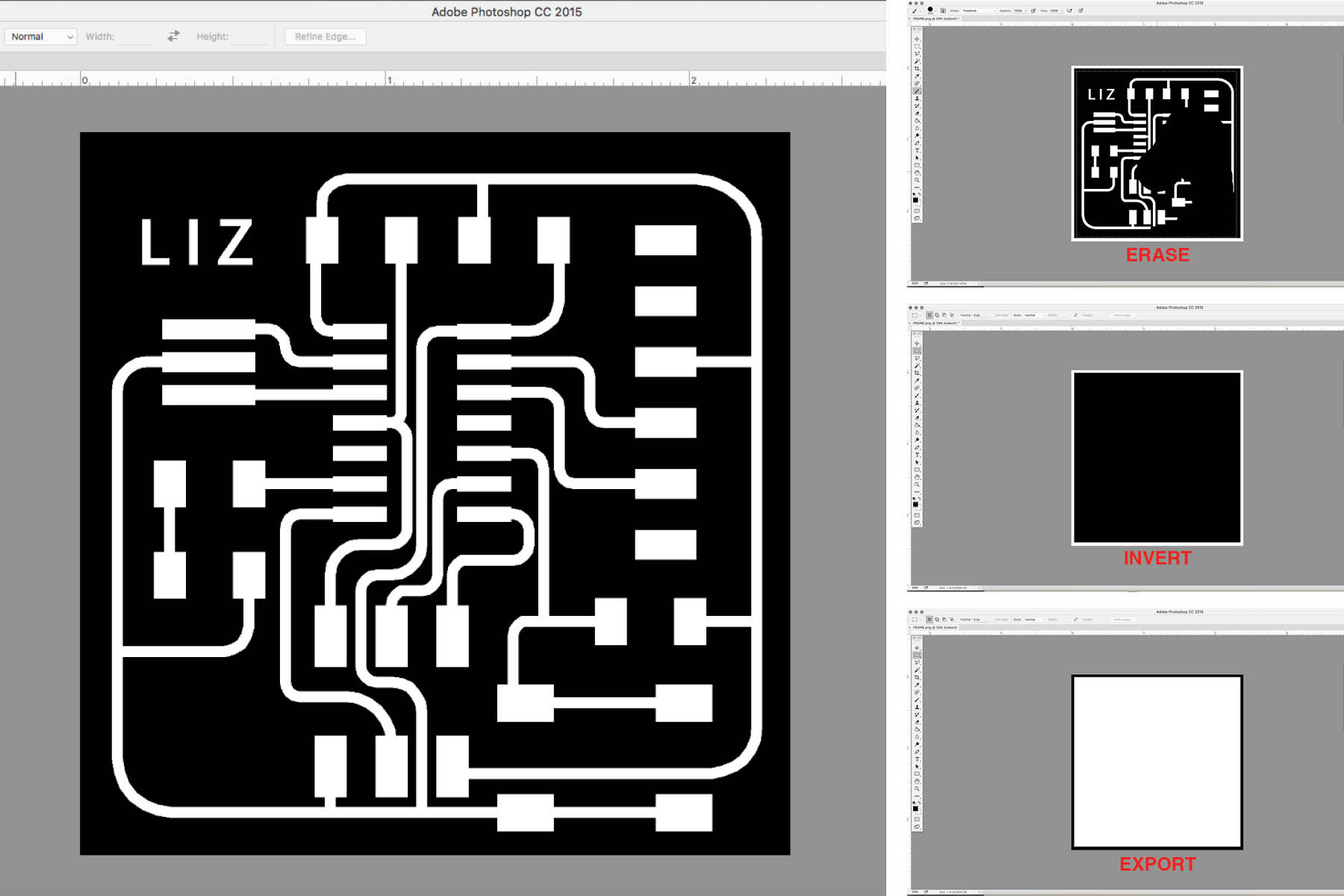
I exported the graphic from Eagle as a monochrome PNG. I then took it into Adobe Photoshop to clean up a few lines and add my name. I also made the PNG for the frame at this time (images above on right). I didn't realize how many problems I had until I started the milling process.
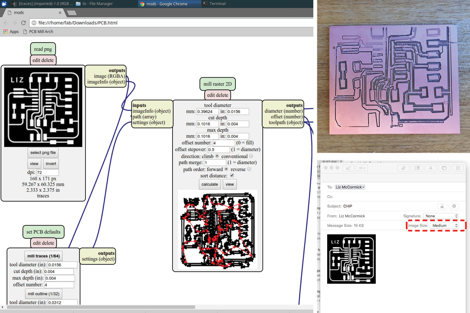
Mistake number one: I have a macbook pro with Retina display, so Eagle actually exported the image at 1000 dpi, instead of the desired 500 dpi. When I sent this to the printer, it printed twice the actual size.
Mistake number two: This is really dumb. When I emailed the file to myself to open it on the shop computer, I didn't check what size I was sending the file as. Mac mail will scale your attachments if you don't select "actual size". You can see the image above (bottom right) where I had "medium" selected as the image size.
Needless to say, this did not print well. I probably should have known by looking at the mill paths.

Next lesson - my traces were too fat. You can see a few spots in the red boxes where they mush into eachother.
The images on the left show the PNG's I sent to the mill - the top one had the fat lines and the bottom one was the updated "final" version. The final one ended up having this problem in one spot - can you guess where?
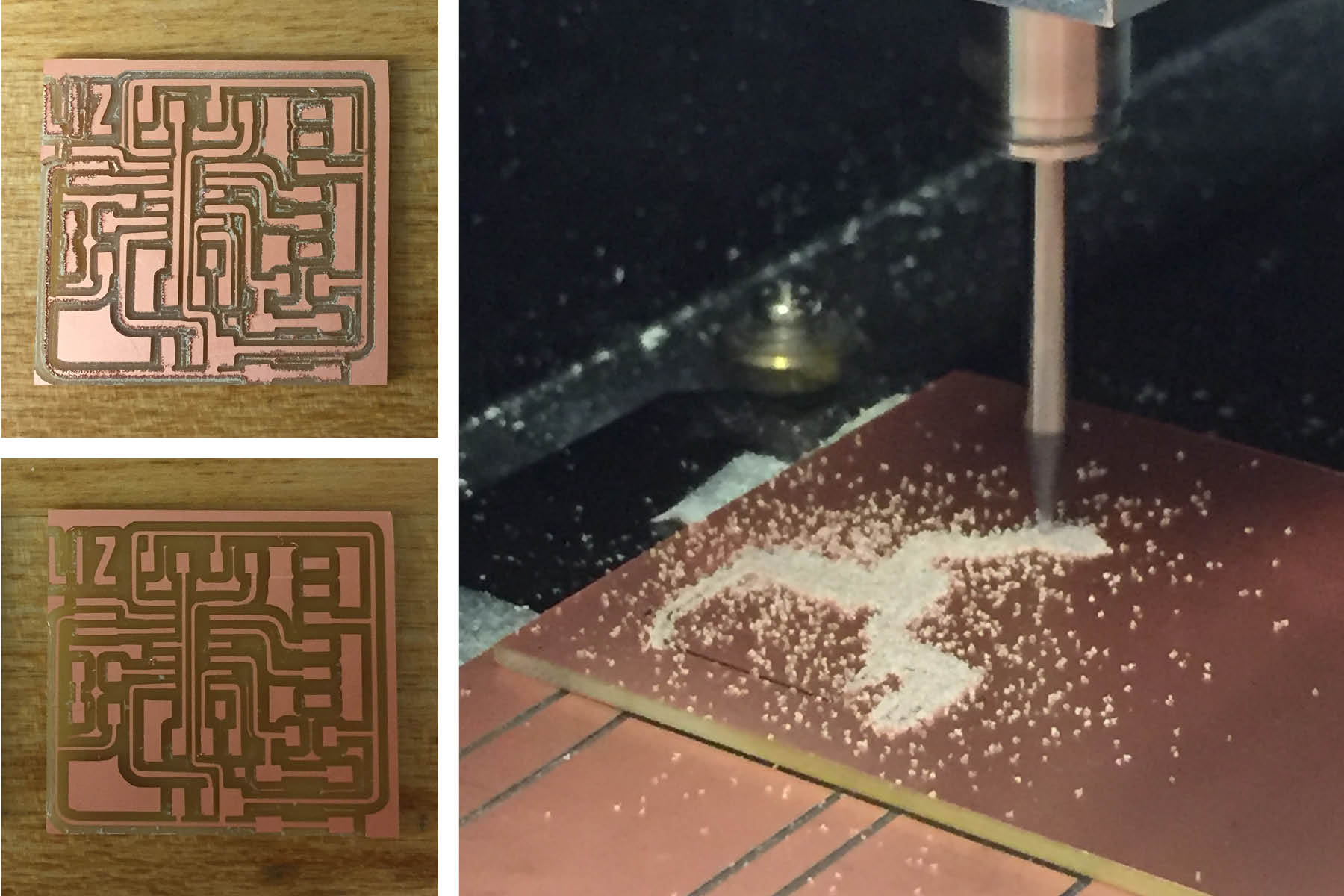
The top left image was the first attempt - after pullit it off the bed, it was not very cleanly cut. I could probably still use this, but I really did not like looking at it.
I inspected the endmill and saw a small chip, so I changed that out and had more success with the next cut. The bottom left image was the next cut and the board I actually used for soldering.

Here you can see my struggles. From left to right: 1. wrong resolution, 2. traces too fat, 3. broken endmill, 4. JUST RIGHT (almost)
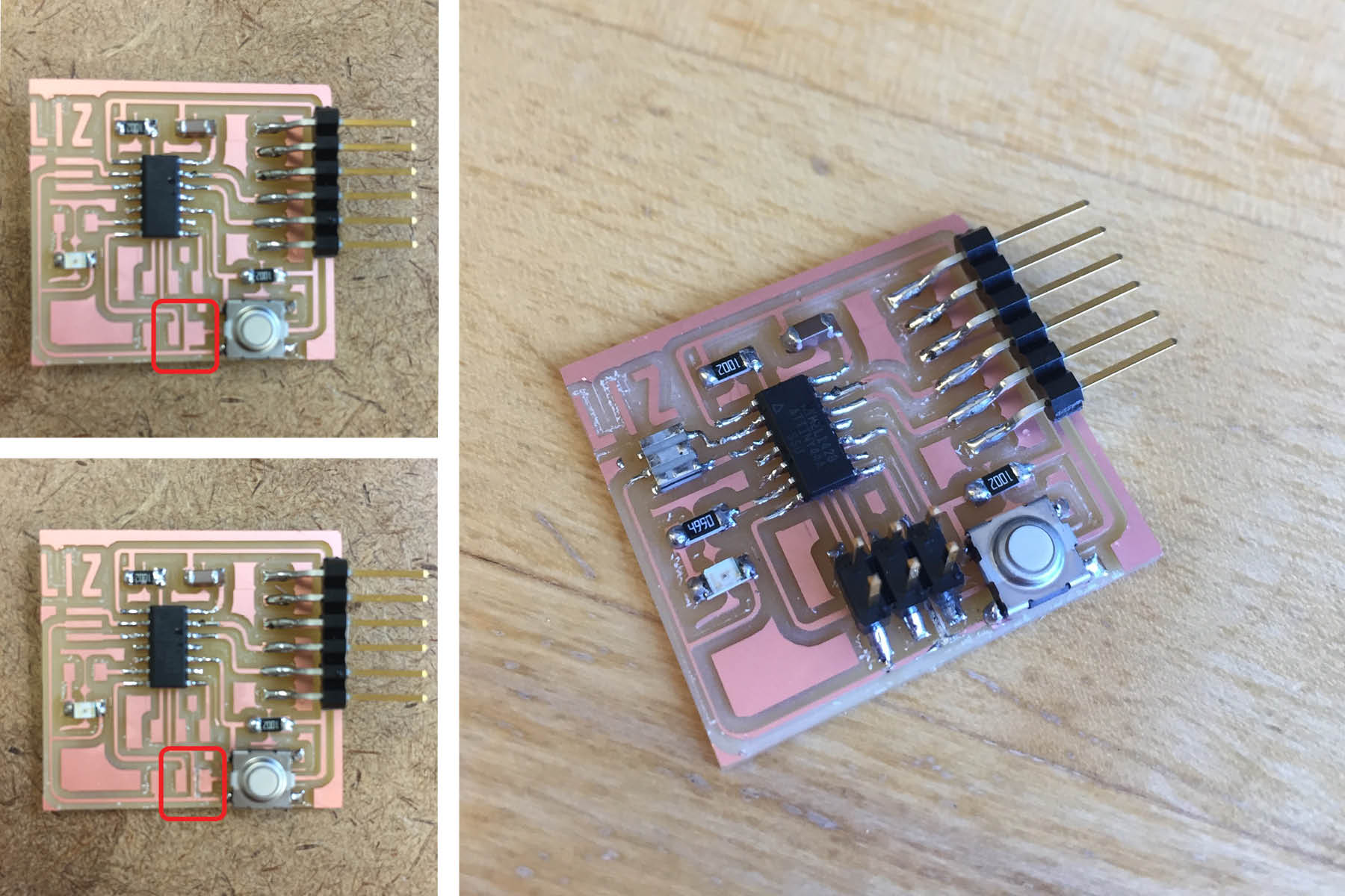
I didn't realize it until I was halfway through the stuffing process, but I had one line that was too close to one of the plates for the programmer - you can see it in the left images below. I cut it manually with a knife to make sure the two charges would be separate. After cutting it, I cleaned it up with some solder to make sure the paths were continuous.
Now let's program this thing.


