Assignment 10: Output Devices
Update: I got servo motors working in interface and application week.
This is a great week because not only the motor worked on my board, but also I figured out my problem during the input device week!
First I started to look at different motors. For my final project, I want to rotate the eyeball and eyelid as the reaction to light, so the servo motor which can control the position is more like what I want. A servo motor is closed-loop servomechanism that uses position feedback to control the motion.
A very useful servo motor tutorial: Servo connection.
How does a servo motor work: Servo motor basic .
Also, this week Calvin did a DC motor demo for us. DC motor uses PWM as speed control. I looked at the pulse width modulation on Arduino website:
"Pulse Width Modulation, or PWM, is a technique for getting analog results with digital means. Digital control is used to create a square wave, a signal switched between on and off. This on-off pattern can simulate voltages in between full on (5 Volts) and off (0 Volts) by changing the portion of the time the signal spends on versus the time that the signal spends off. The duration of "on time" is called the pulse width. To get varying analog values, you change, or modulate, that pulse width. If you repeat this on-off pattern fast enough with an LED for example, the result is as if the signal is a steady voltage between 0 and 5v controlling the brightness of the LED."
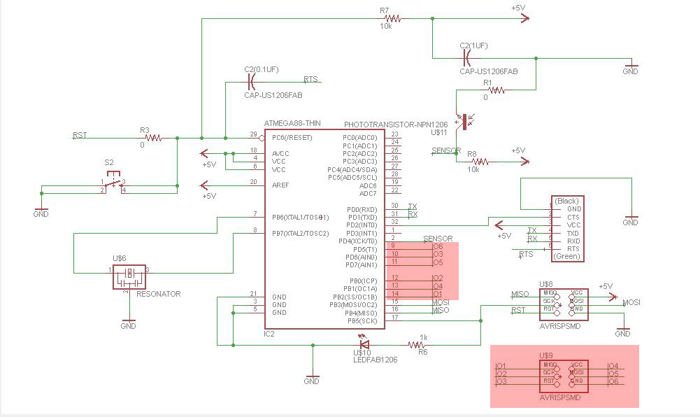
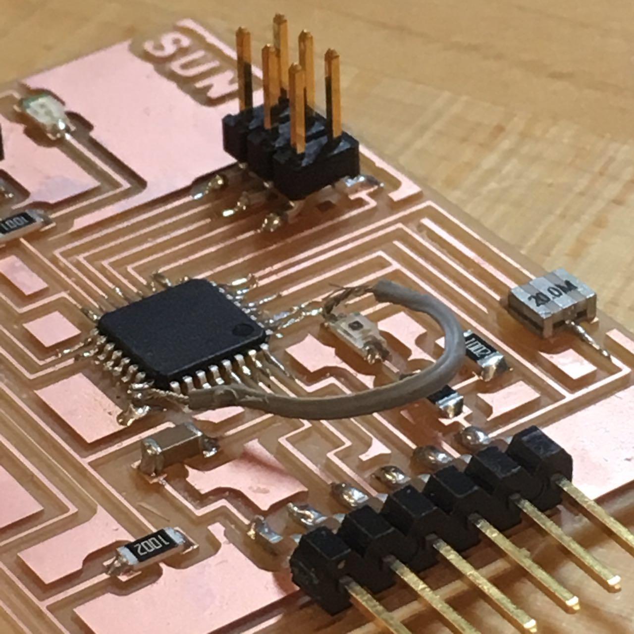
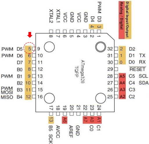
Similarly, as for servo, it should be connected to VCC, GND and a digital pin on microcontroller. Differently, servo motor has the bridge built in. Servo should get it is power from a source such as a battery. Below is the board scheme I designed in the input week (used "hello.arduino.328P" as basement), the i/o pins can be used to connect output devices. I used PD5 to connect my servo, in arduino IDE, it is pin 5 as a digital signal pin.
|
|
Wiring up and programming
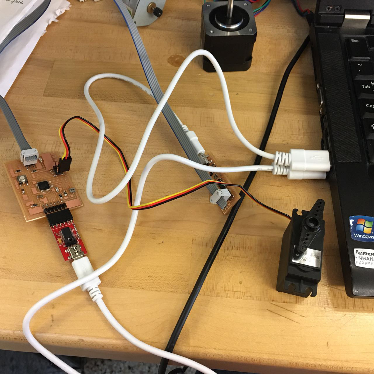
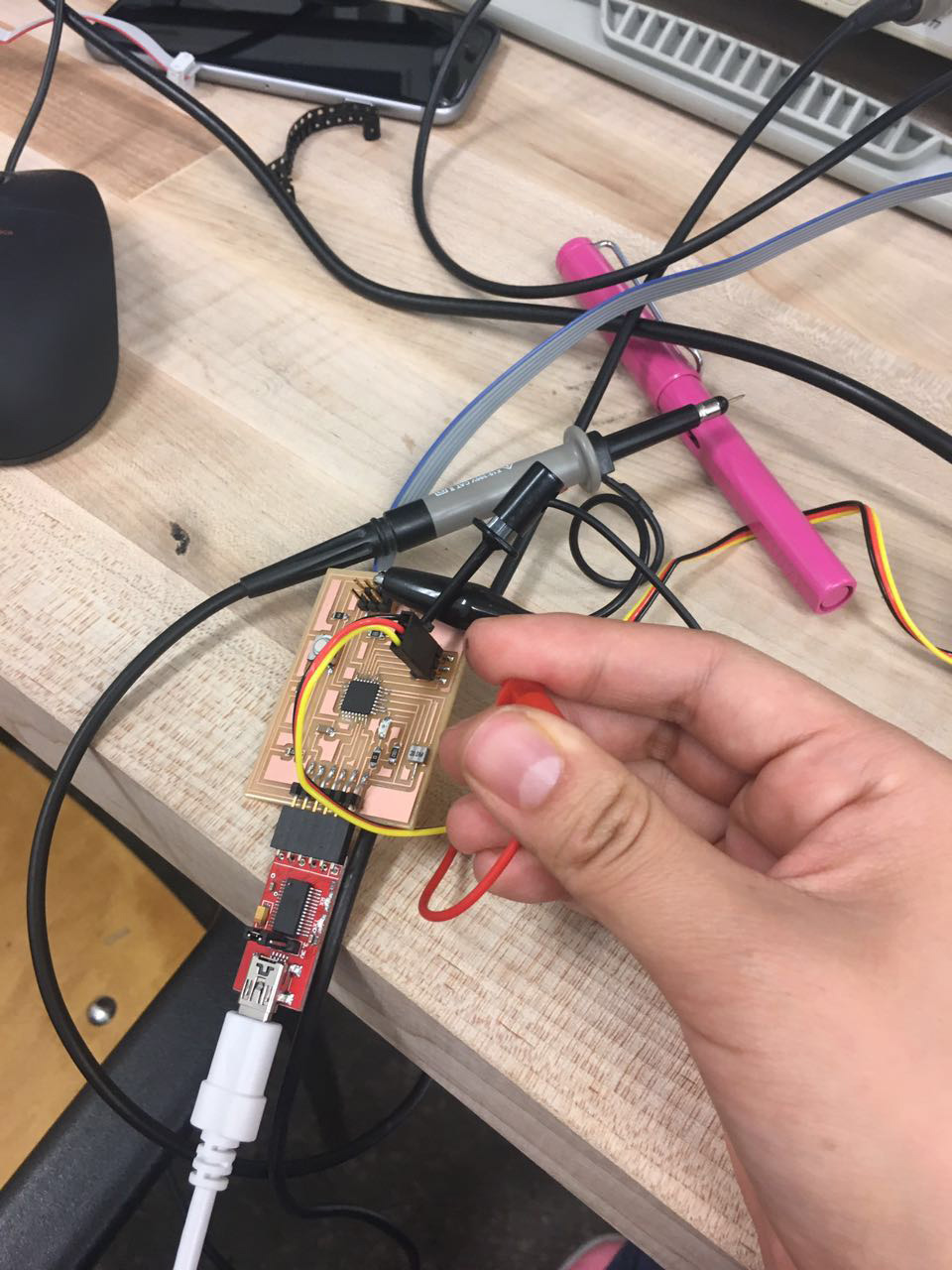
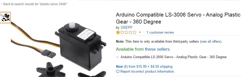
After basic understanding of motors, I began to wire up. Usually there are three connections. Power is the red one, ground is the black one and usually signal is the yellow/ white wire. I used Plastic LS-3006 servo motor and the voltage rating for it is from 4.5 to 6V. I connected the signal wire to pin 5, which is a digital/PWM pin. Since my battery is 9V, exceeding the maximum voltage of the motor, so I went to shop and used DC power supply.
|
|
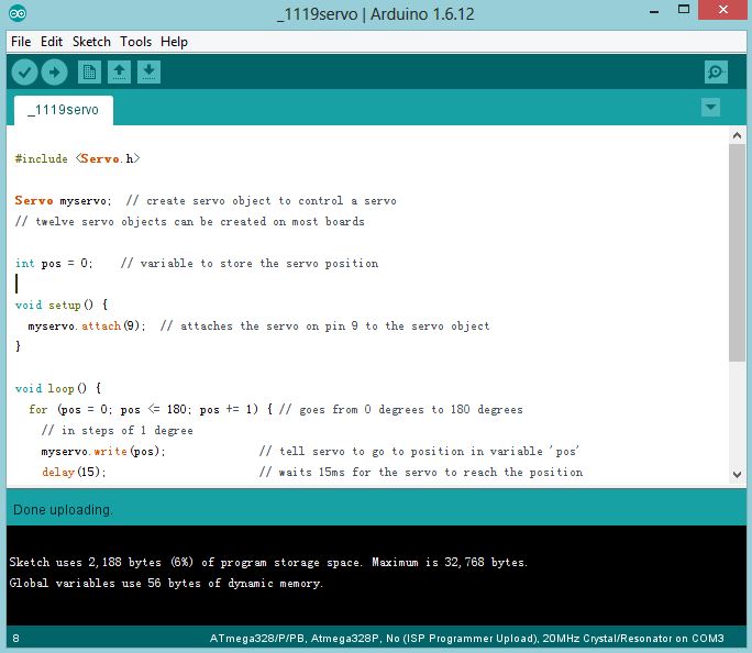
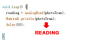
Below is my code in Arduino IDE. Programming went smoothly. But when I provided power to my motor, it did not behave like my code.
|
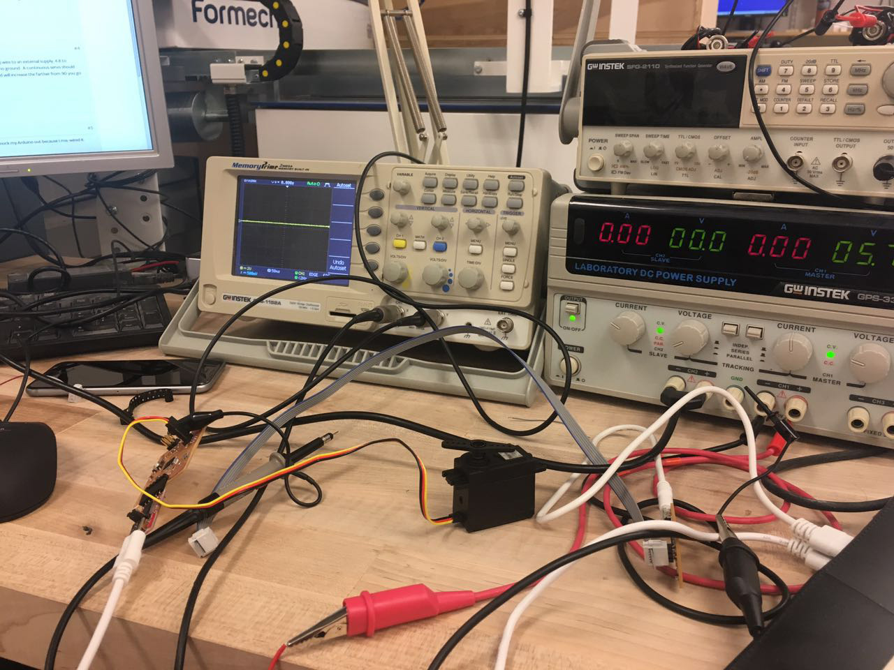
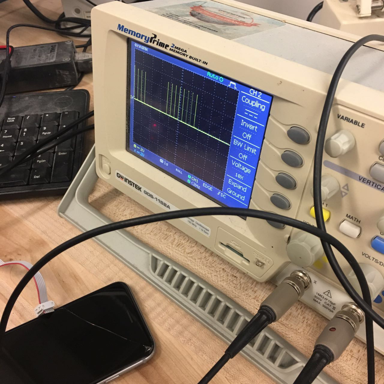
Calvin used oscilloscope to diagnose my board. We figured out pin 9 in my code actually is another output pin which reacted. After double checking the atmega pinout, I found that the pin I connected my motor is actually pin 5. It is very important to pay attention to the digital/ analog pins when wiring up and coding.
|
Then I uploaded the code again, and this time the motor began to rotate!
|
| |
We then changed the direction of rotation, but soon found the motor could not change direction. Calvin used OSC to diagnose the pin, found out that it did output the signal we want.
|
We went back to the servo data sheet (as well as information on amazon), found out this servo is a continuous motor! It only rotated in one direction. We are out of servo motors, and my own order is still on the way, since basically the motor worked, I began to play with my board.

|
|
Fixing serial communication
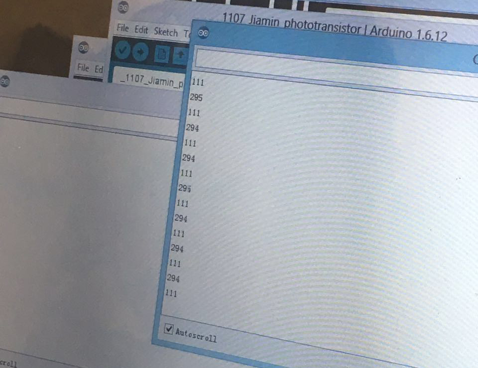
As I posted in the input devices week, there is a serial communication problem when I programed my board with a phototransistor. The monitor kept rolling and did not print out anything. This week with Calvin’s help, we figured out that I’ve made two mistakes.
First, in my code, I should say print 'reading' instead of print 'phototran'. And I also double checked if Serial.begin() and baud in serial monitor match. After several attempts the serial monitor began to print numbers! But I soon found the numbers did not change according to the light environment surrounded the phototransistor. Then I went back to my scheme and found out the second mistake.
|
The second mistake is I connected the phototransistor into a digital pin. When we went back to the datasheet and the basics of phototransistor, I understood that the device I used is an analog sensor. below is how the phototransistor works:
"For a given amount of electric current, more voltage (pressure) is lost across a larger resistor than a smaller resistor that has the same amount of current passing through it. If you instead keep the resistance constant and vary the current, you can measure a larger voltage (pressure drop) across the same resistor with more current, or less voltage with less current. The reason the voltage changes with light is because the phototransistor lets more current pass when more light shines on it, or less current pass with less light. "
Reference: Phototransistor arduino.
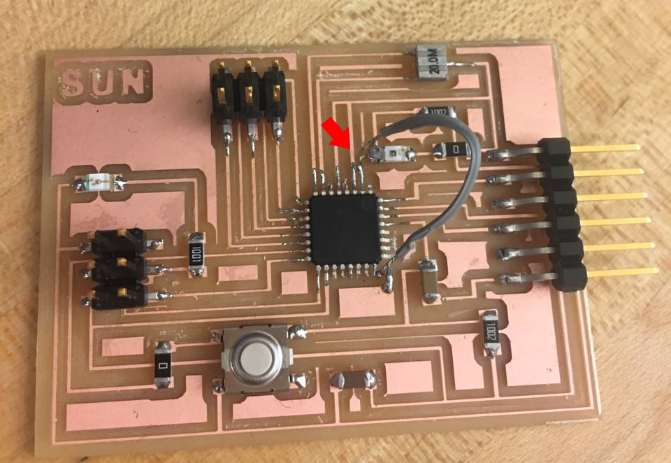
So I added a jumper to connect the collector of the phototransistor and pin A1, which is an analog pin. We thought this would work, but this time after I programmed it, the serial monitor started to print ‘0’ all the time! I went back to my scheme, double checked the direction, and found nothing. Then I checked my board and found when adding jumper, the collector was accidentally connected to the ground.
|
So I cleared the solder, and this time everything worked! The phototransistor started measuring the light.
|
| |
Spending the whole afternoon debugging and testing, I figured out a lot of issues towards input/output devices. I will make my input and output devices communicate soon.