Assignment 4: Electronics Design
For me, this week's assignment is a topic I am completed not familiar with. First I started reviewing basic knowledge of electronics and microcontroller. I am familiar with the basic conceptions, such as ohm's law and Kirchoff's laws. But for micro control, the ATTiny 44 is new to me.
Two useful references:
1. AVR tutorial: http://www.ladyada.net/learn/avr/index.html (Shorter than the manual of 8-bit AVR).
2. Jean and Palash's Electronics 101.
Electronics Design
I started with eagle. First I went through Ali’s notes on creating components in eagle, also the tutorials on Youtube. Eagle is user-unfriendly, however since I am familiar with drawing in AutoCad, I got adapt to the rule of eagle quickly. My first design was complicated and not clear, also there were a lot of warning when testing. By learning and adjusting (like 6 times redrawing), I competed my scheme.
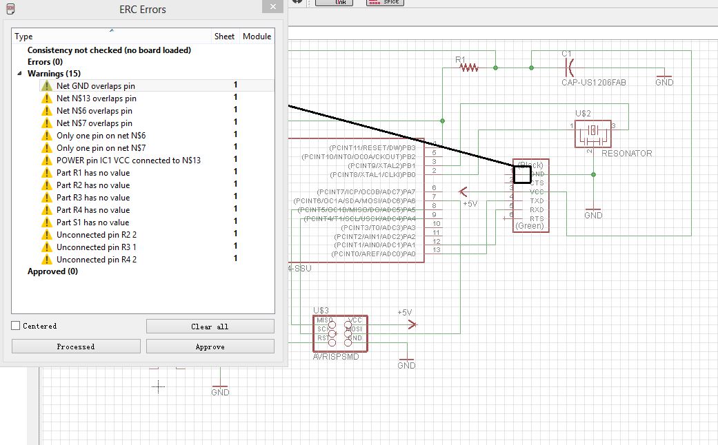 |
When doing redrawing and adding components in eagle, there were several important issues I noticed and learned. Below are my steps and the important notes:
1). Redrawing: When drawing lines in eagle, “wire” is better for connecting components, and “net” is better for creating lines and joints. Also, to make the circuit clearer, “name” and “label” are useful tools.
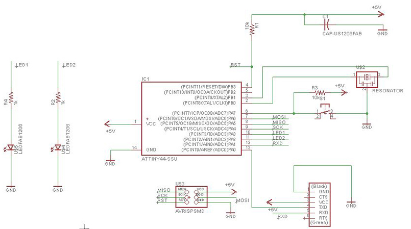
2). Button: When beginning, I was confused with the button. I read the basic conception of ATtiny44, and my understanding was that when the RESET pin is at ground, the chip would stop and listen for programming instructions on the programming pins. Then Hunmin and Neil showed me that if I connect my button to the reset pin, my board will stop working every time I hit it. The reset pin is connected to a button in commercial board, in order to kill the micro controller when errors happen. The button for this class is to get an input and then the LED could be controlled.
Also, to ensure the running of the program, it is better to give the button a VCC and a resistor.
3). LEDs: I added two LEDs to two free pins. Each LED was connected to a resistor preventing overload.
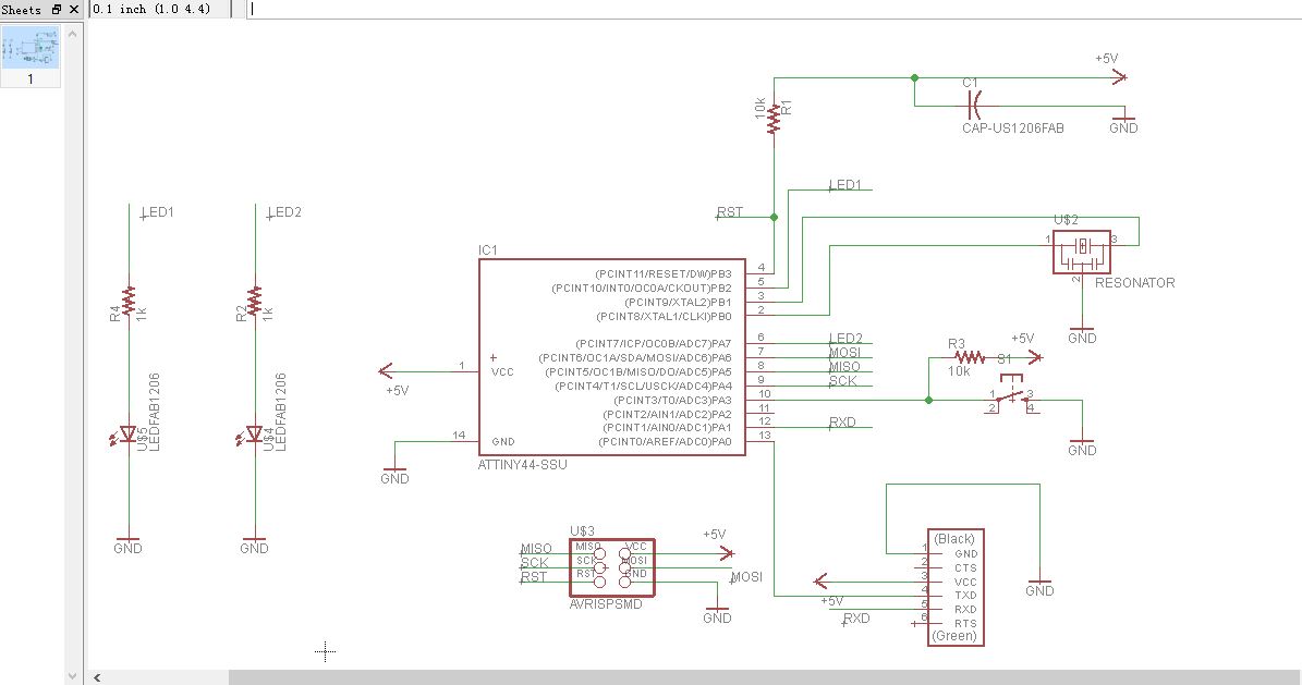
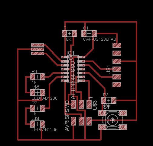
My final design:
 |
Board Design
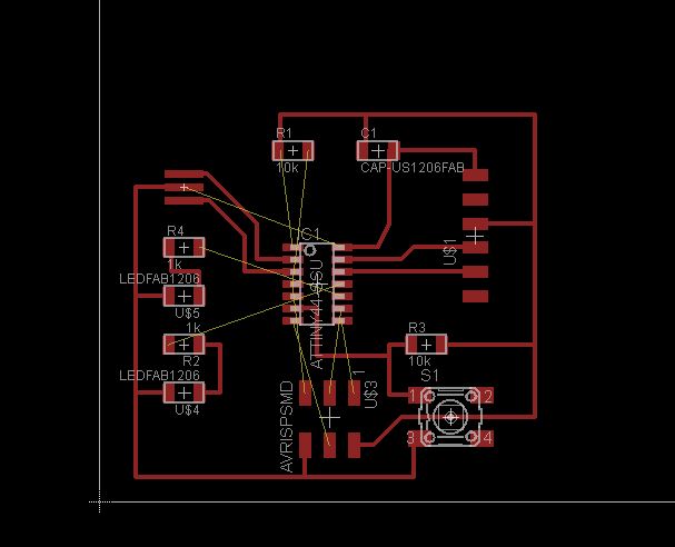
After transforming into board view, I did not use the "autoroute" function (which I found may create multiple layers), and I routed between the components one by one.
1). At first it was difficult for me to connect some components without crossing. I figured this out by adjusting the position of my LEDs and button in my original scheme, and made them easier to connect the pins.
 |
Design adjustment:
 |
2). The gap between the lines matters. If the gap is not wide enough, the milling machine would not recognize it. The right way is either to make the lines thinner, or to try other routes. The outline has the same issue, thus, keeping the outline thicker than the routes is a safe way to ensure recognition. Finally I added my name and the outline in Photoshop.
 |
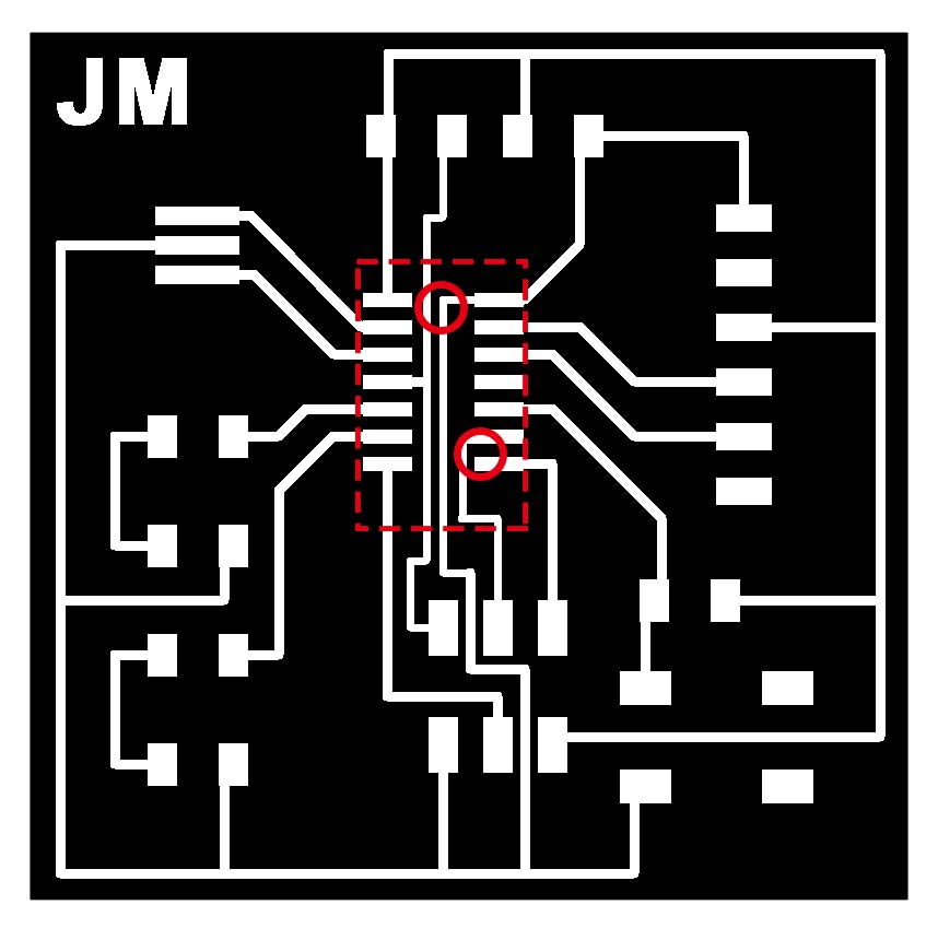 |
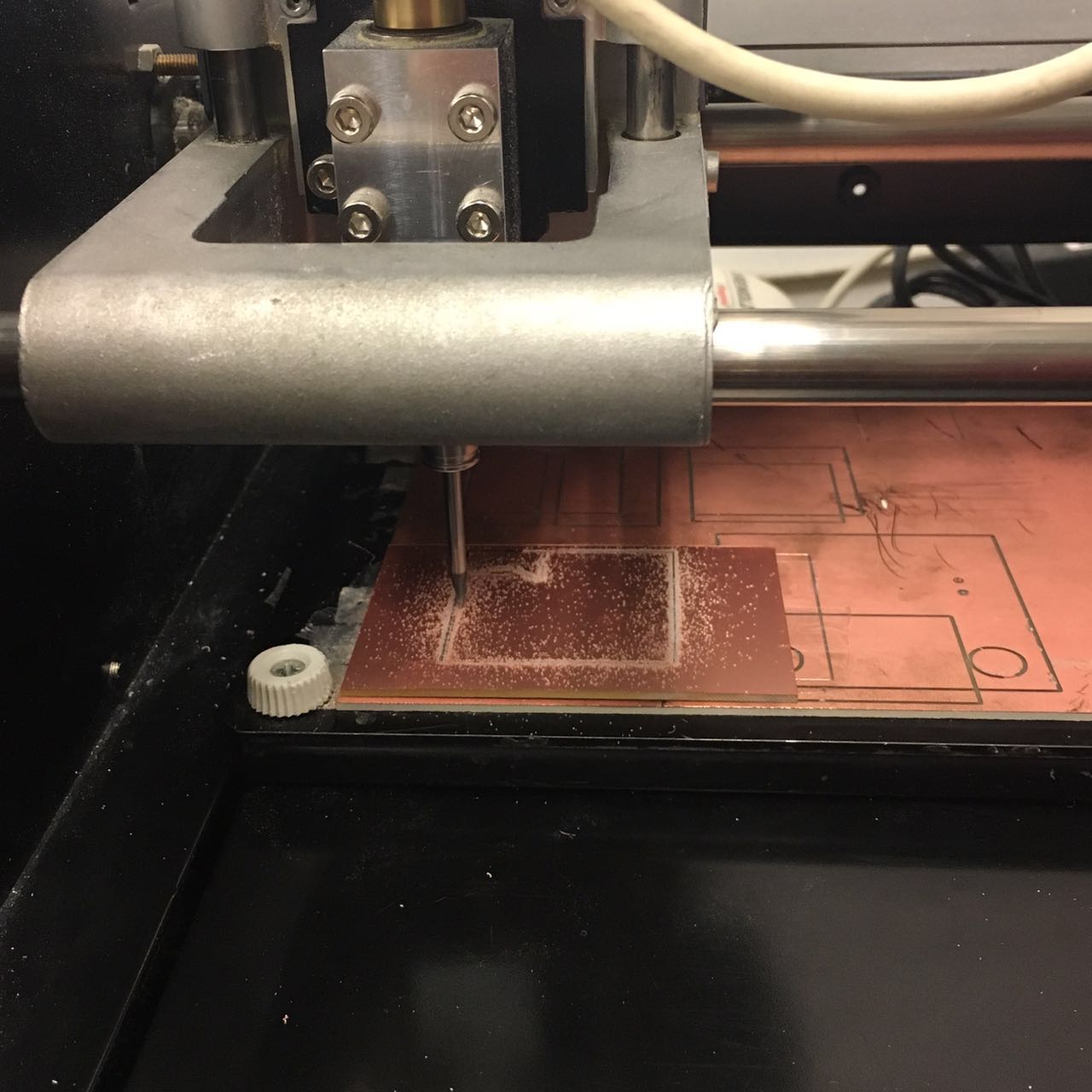
Fabrication
We did milling and soldering two weeks before. After designing, the process of fabrication is the same as making the programmer. However when milling, I still failed once. As I mentioned before, the gap between the routes matters. Mine was too thin to be recognized by the machine. So I modified my PNG files and milled my board.
 |
 |
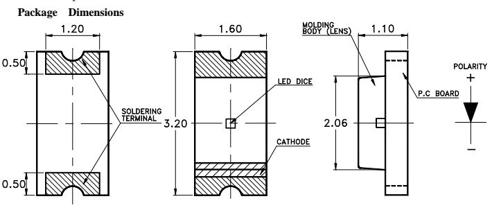
When soldering, I noticed that except for ATTiny44, LEDs also have directions. Usually the cathode should be connected to the ground, and anode to VCC. I chose the blue and the yellow LED, on the surface and the bottom I could find the indicator of the polarities of the blue one. For the yellow one (LTW-150TK), there is no clear indicator on the surface. I also looked through the data sheet and was still not sure for the polarity. Finally Justin helped me to multimeter to test it by multimeter.
Below is the indicator on the datasheet of LTW-150TK:
 |
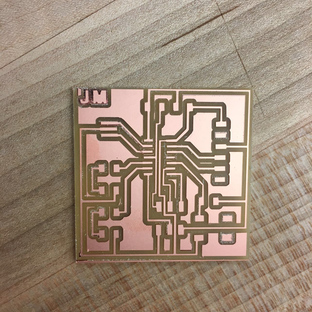
Soldering and my final board:
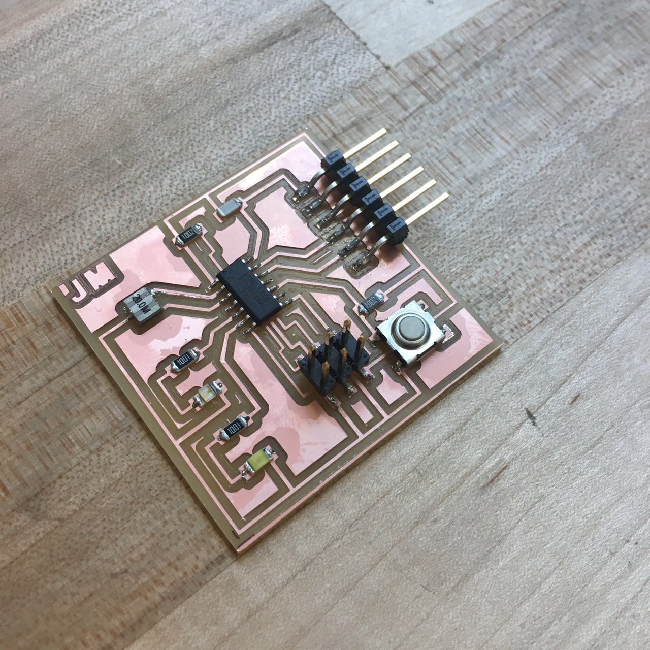 |
Look forward to testing and programming it in the next two weeks.Thanks to my labmate Yijiang Huang, who helped me to understand the microcontroller. Also thanks to Justin and Hunmin!