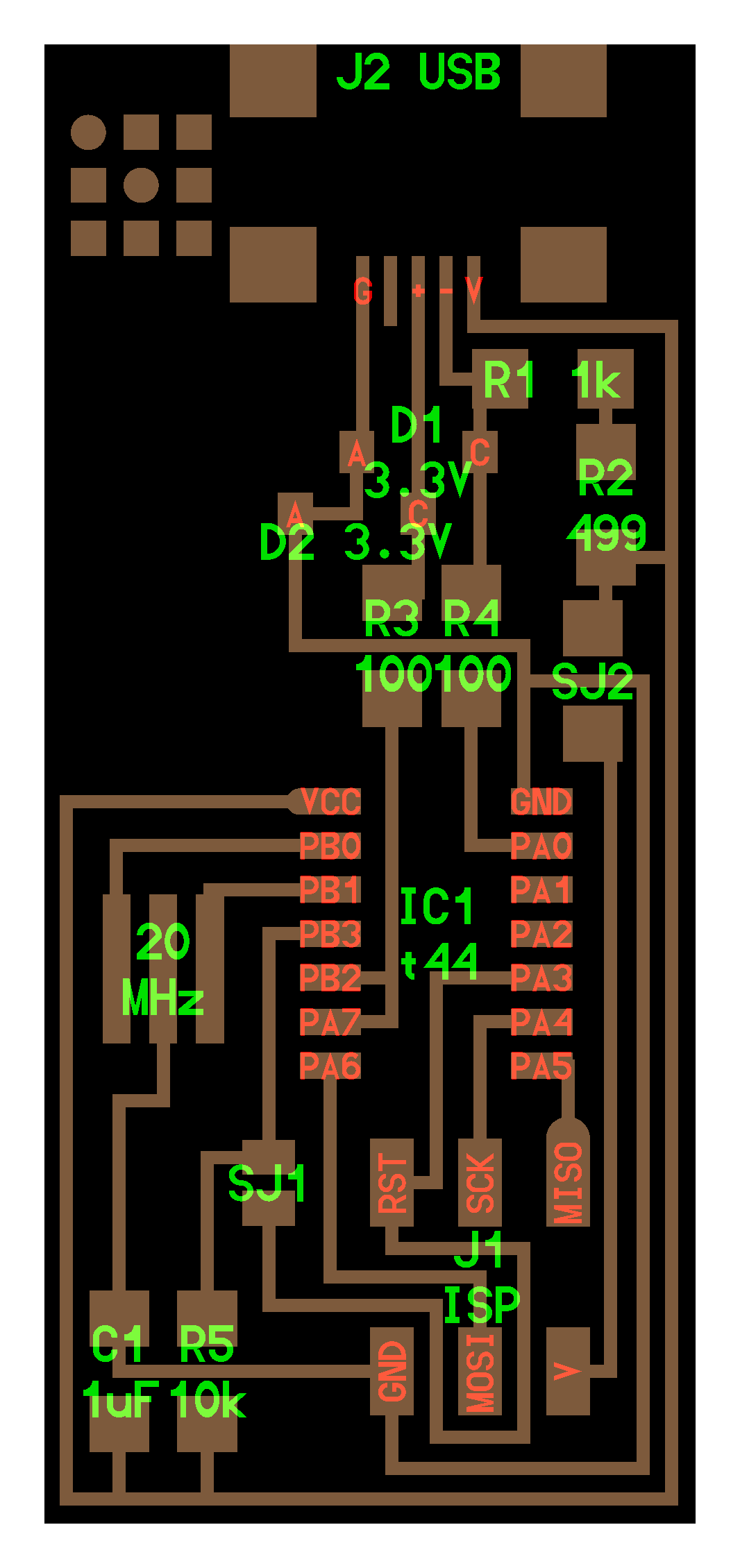
This project was less on the creative side since everyone was required to make the same product. I simply followed instructions and used the designs provided to cut and solder the board.
CUTTING
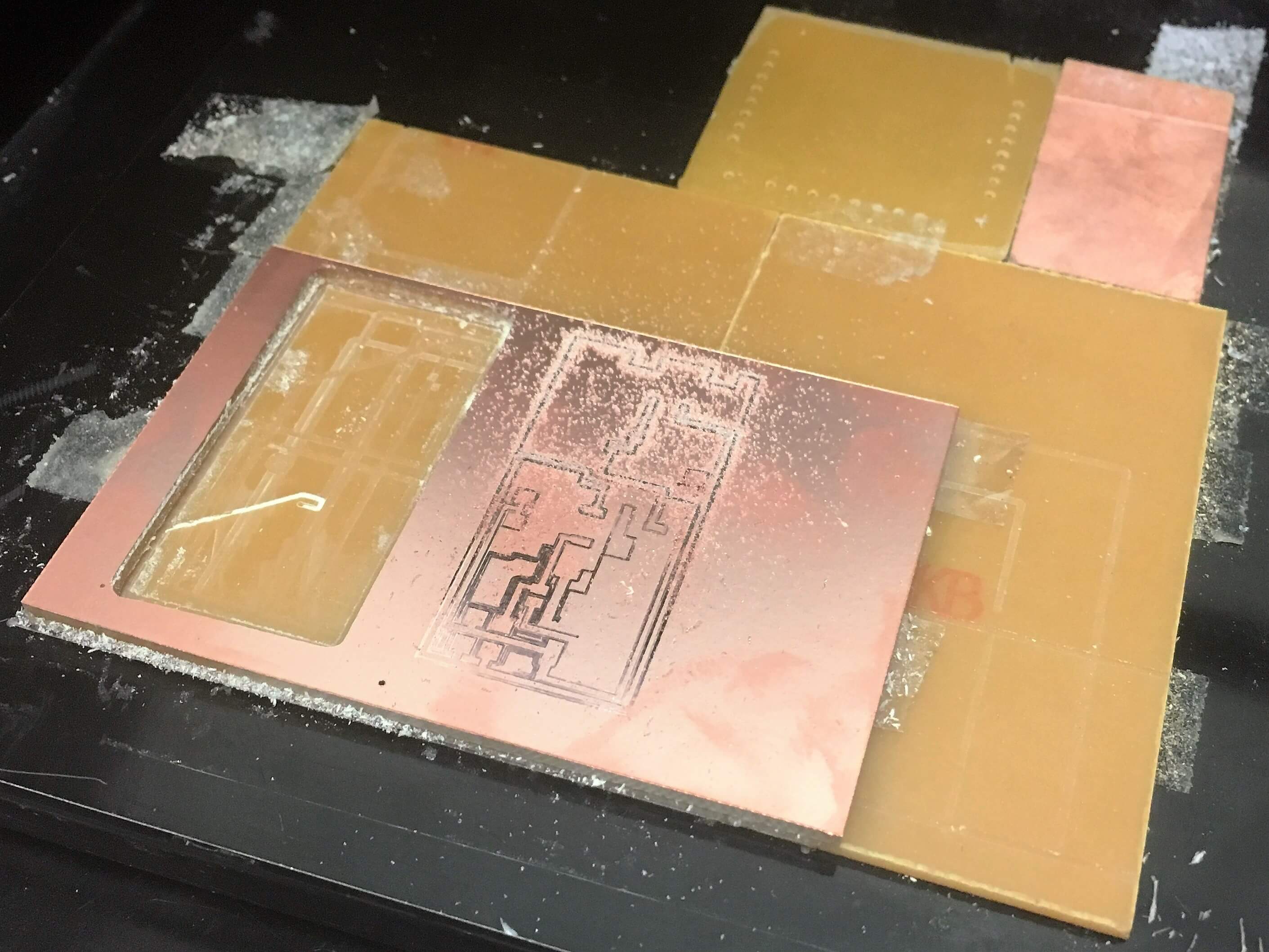
I started off by putting the plate on the mill. I stuck double-sided tape on the back of the board (the non-shiny side) so that it would stick to the sacrificial buffer board. To make sure that the board was even, I made sure that none of the double-sided tapes overlapped.
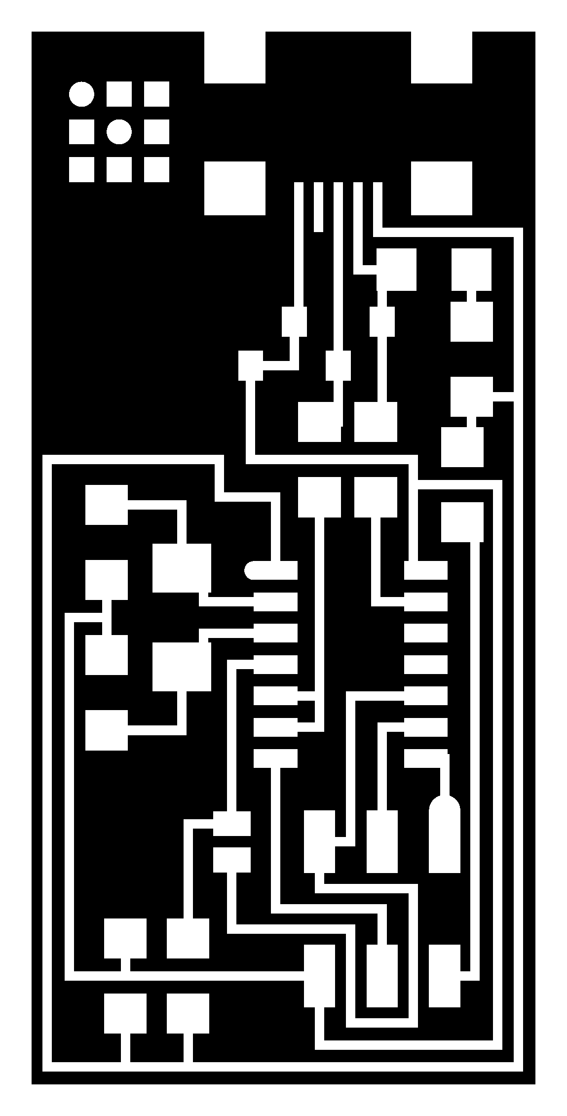
To start etching out the circuit design, we needed to upload a PNG of our design to MDX 20, a program. I used the 1/64 end mill. I had to insert the end mill into the machine, making sure that the machine wasn’t set too close to the board (otherwise it can’t go any lower to cut).
z was set to 0 on an arbitrary corner of the board. The cutting path was calculated, and cutting began.
The machine had to be stopped very quickly because parts of the circuit were cutting through while others weren’t.
It was obvious to see the imbalance early on.
As it turns out, the sacrificial was not level, and some of us discovered that the lowest point was the top left corner (relative to where the user stands). We tried again, adjusting the end mill to the lowest corner.
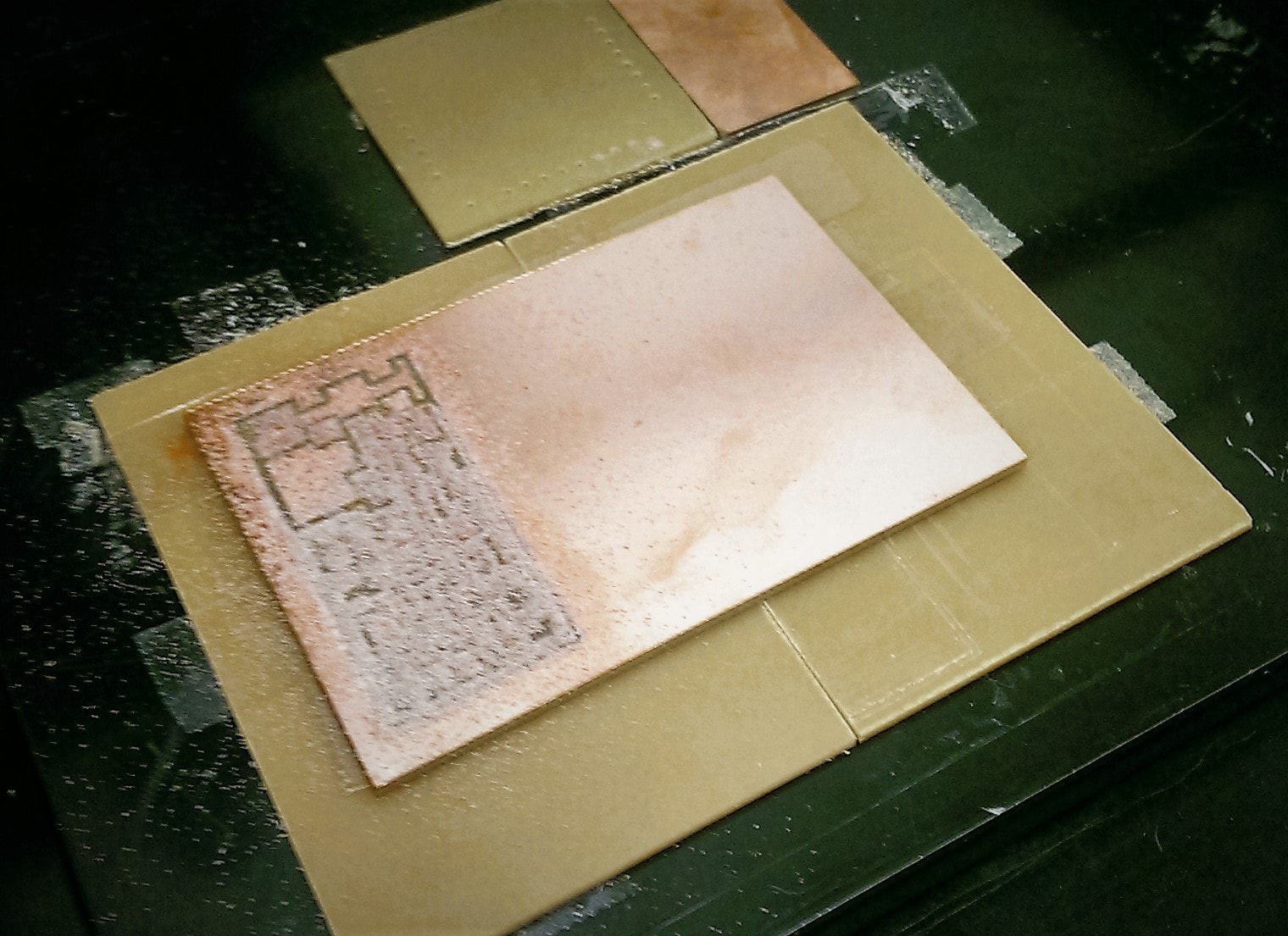
Once that was done, I vacuumed the board. This part was incredibly satisfying.
I then used the 1/32 mill to cut out the actual board. The mill would go around 3 times. Again, I did this by uploading the PNG of the design up and sending it to the mill.
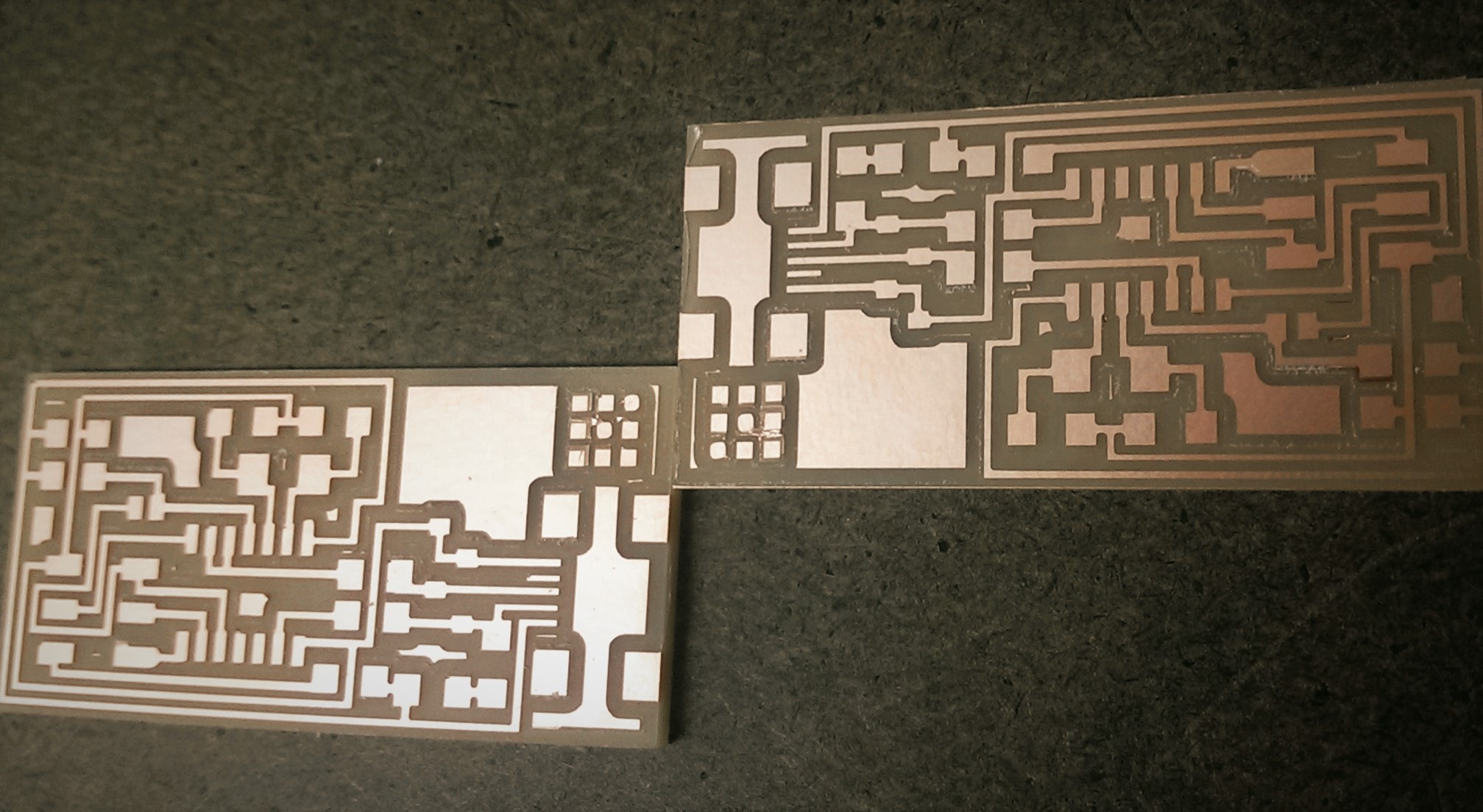
I saw someone else do this before me, and their board got loose because the board technically cuts through after mill goes around the second time. The board ended up ricocheting and the end mill damaged that board’s design. Because of this, I made sure that I had a ton of double-sided tape. Unfortunately, this made it very difficult to remove my cut board from the buffer board.
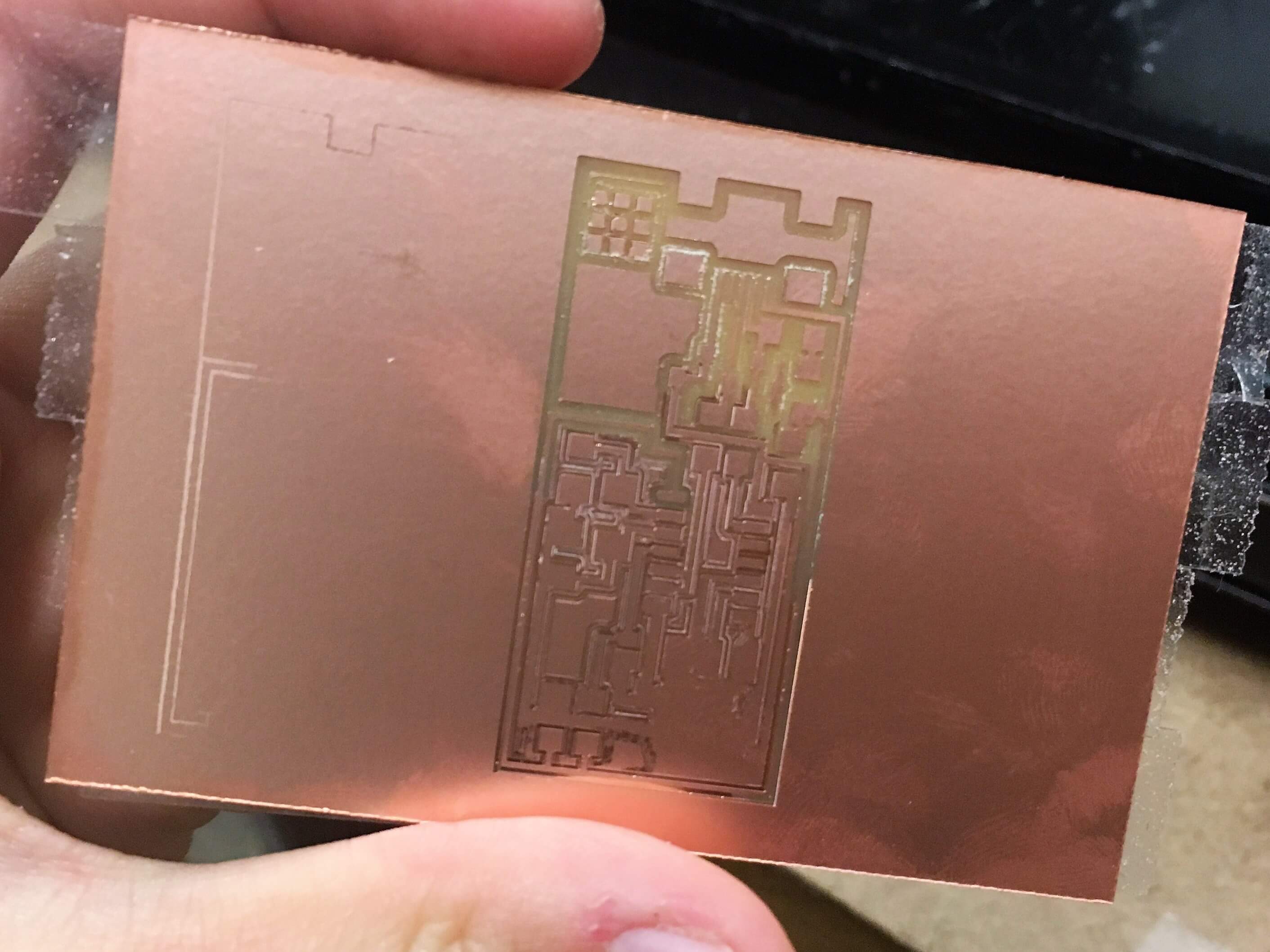
I finally got them out! I noticed that there were parts of the 3x3 corner grid that didn’t cut too cleanly. I tried cutting the copper layer with a knife, but upon inspecting the soldering blueprints, I realized that it was irrelevant, so I let it be. The unwanted parts fell off on their own after a few days.
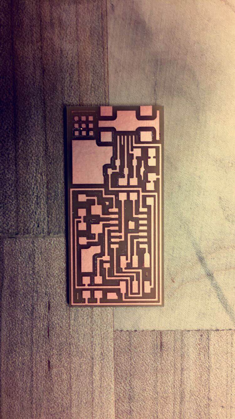
I love how the board looks under this Snapchat filter!
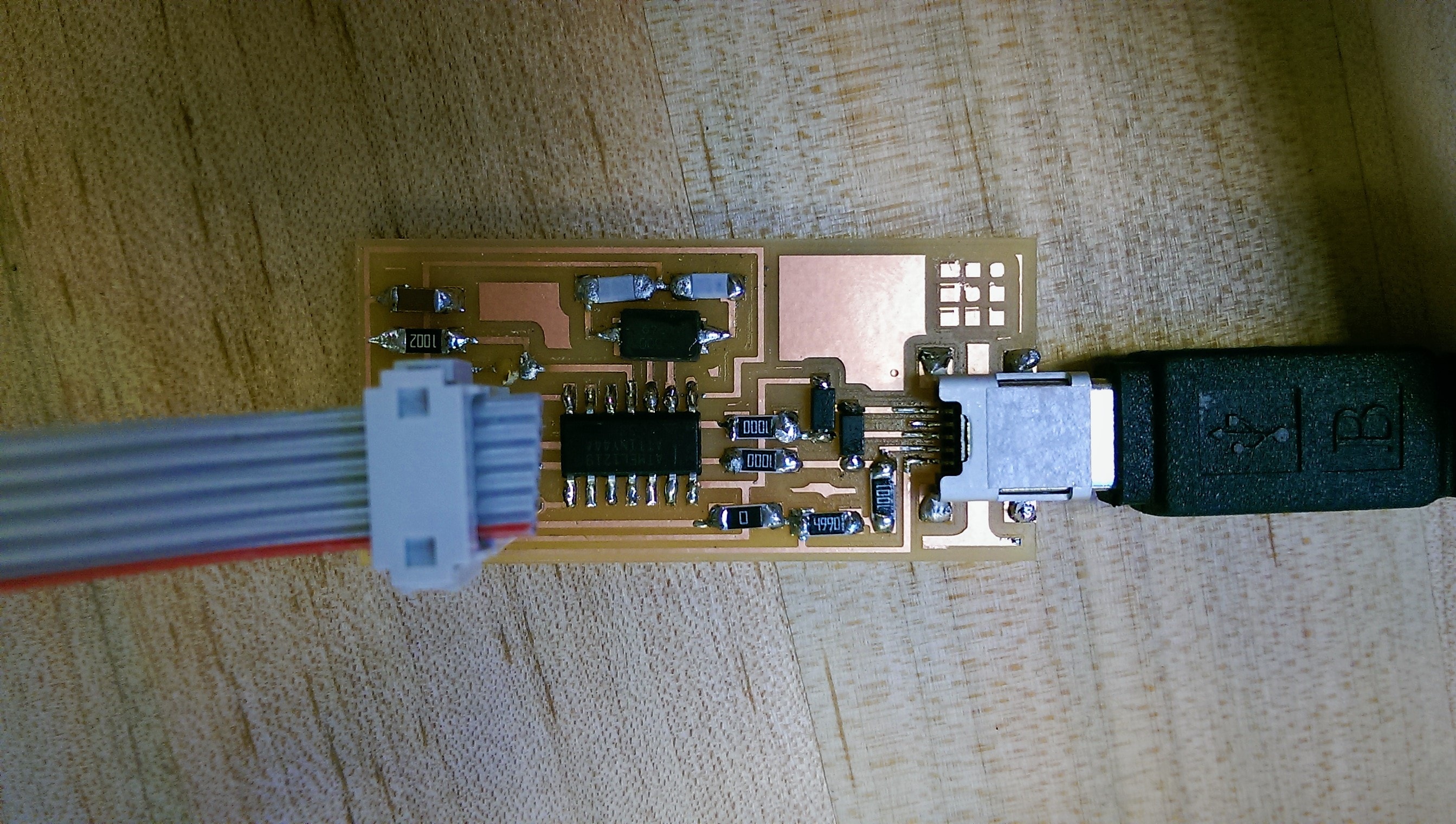
SOLDERING
I had previous experience soldering, so this part was quite straightforward for me. Something that I didn’t anticipate happening was the fact that the solder didn’t want to stick to the board. Luckily, there was flux readily available! Everything got easier with flux.
After I finished soldering the board, I went to the computer to set up the board ready for programming. The image on the website we were given implied that one of the inputs needed to be plugged in a certain way, so I copied the image and the ATAVRISP programmer started blinked yellow.
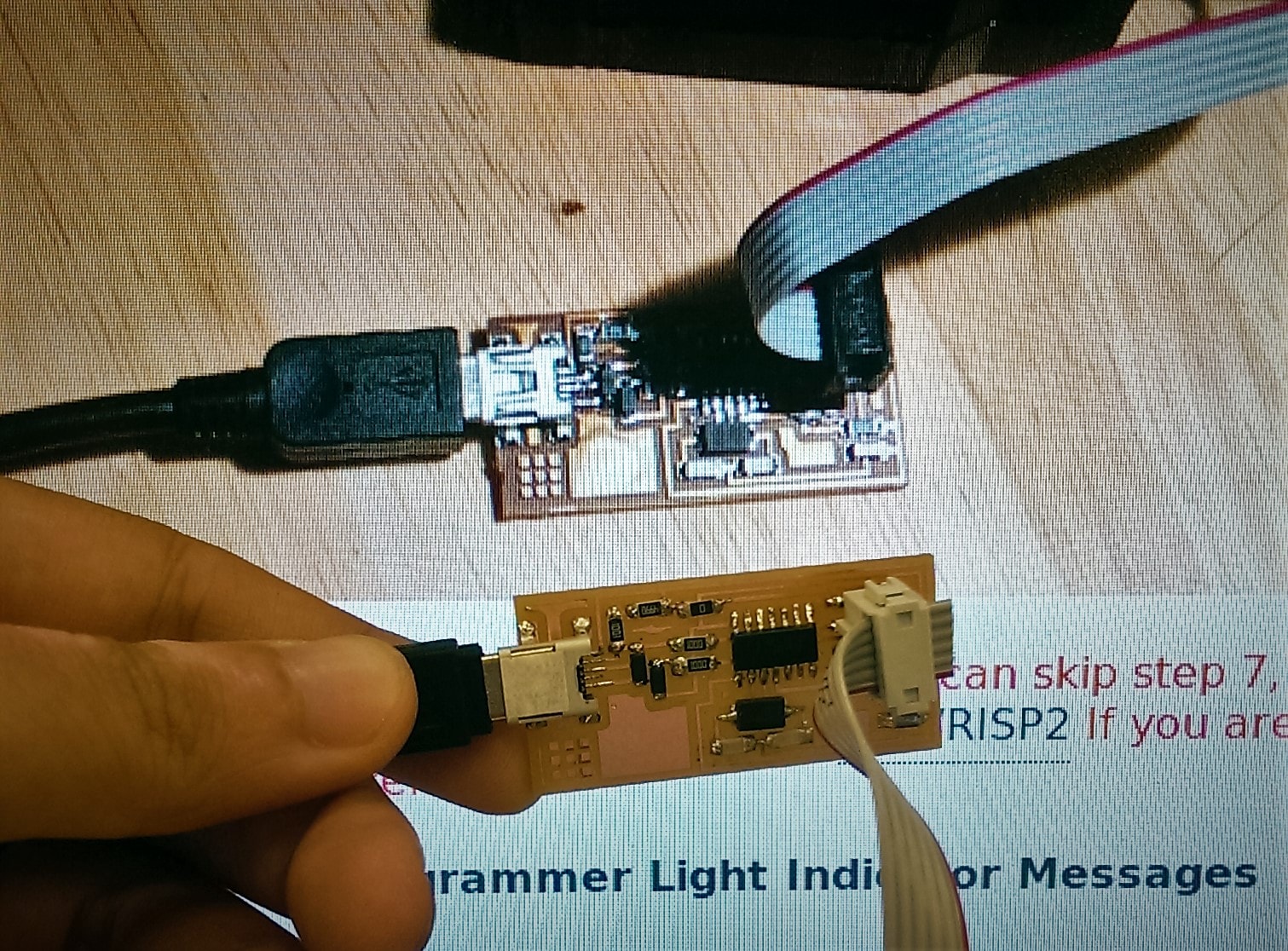
I initially thought that this meant I had soldered something incorrectly, but someone corrected me and apparently I had just plugged it in the wrong way!
I used the following commands to set the board up:
make clean
make hex
make fuse
make program
Then I needed to remove the bonds at SJ1 and SJ2. This was a lot harder than I thought it would be, because to do this, I needed to unsolder one side of the resistor, then the other side. Unfortunately, the solder iron would harden before I could remove both sides. I asked another classmate to help me solder both sides at the same time.
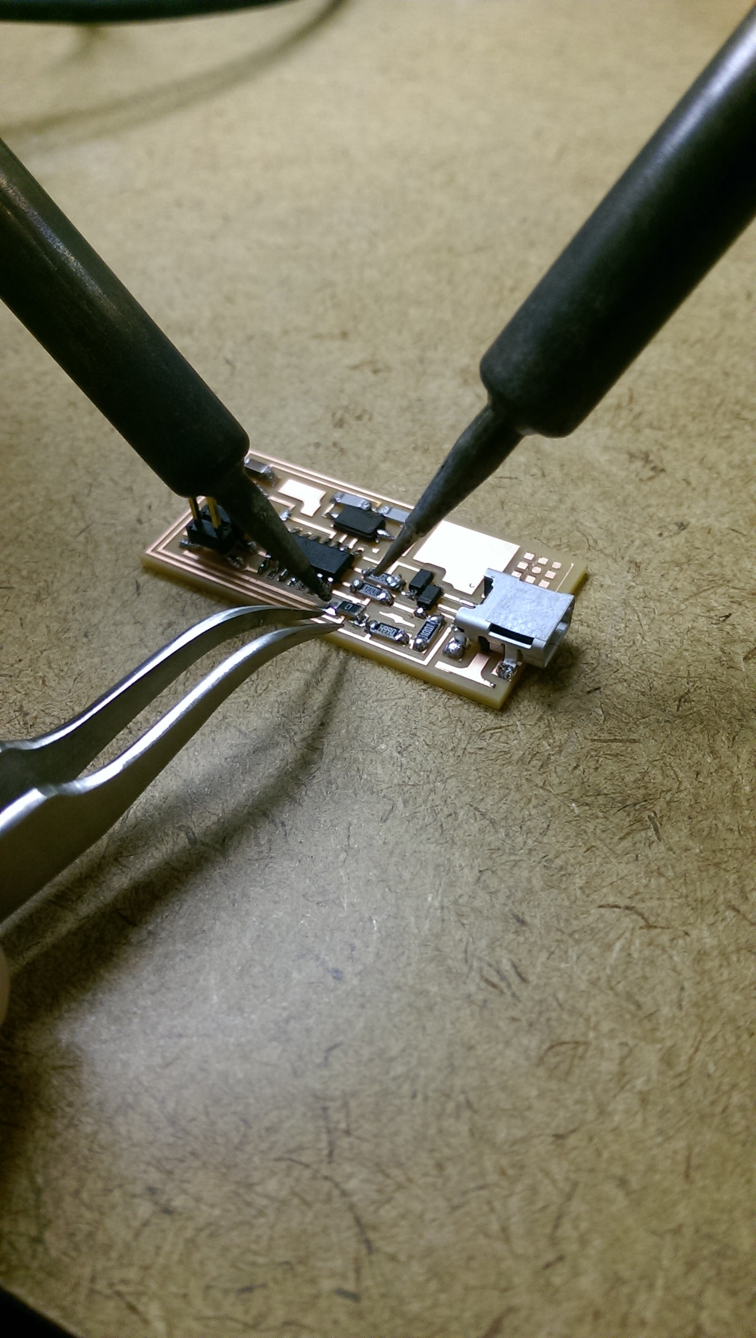
Although I’ve soldered before, I’ve never used tools to remove solder. Some tools that I learned to use were the desoldering pump (fondly nicknamed solder-sucker) and the copper tape. In the past, I would just heat the soldering iron while trying to flick it off and hoping for the best.
I don’t quite have a preference between the two solder removing methods. The desoldering pump was faster, but I found that the solder had to be liquid hot to get sucked up, so the timing had to be perfect. Parts of the copper on my board also got sucked up when I used the desoldering pump, which was worrying.
It took me a while to work out how to use the copper tape. Someone told me that parts of their copper circuit got damaged by the copper tape, so I was a little apprehensive. I found that the copper tape would stick to the board once the solder hardened (which happened very fast), so this was bothersome to deal with. I also found that the copper tape only picks up very minute amounts of the soldering iron. Perhaps there’s a technique to it that I’m missing, but I quickly lost patience and found the copper tape infuriating to use.
I also used flux for the first time. The flux really makes the soldering iron stick to the copper parts of the board, which kept the board neat. In fact, it was almost difficult for me to overflow. I had to intentionally put too much soldering iron when patching SJ1 because the soldering iron refused to land on areas that weren’t part of the copper design.
A lot of time was spent making sure that the design on the board was etched properly. A huge issue that I ran into was the fact that the sacrificial buffer board was at an angle, which meant that calibrating the z of the mill to a certain part of the board did not necessarily correspond to the surface of another part of the board. This meant that parts of the circuit would etch while others wouldn’t.
I initially thought that this imbalance was due to tape overlap or dust underneath the board. Several classmates and I were trying to figure it out. We used an iPhone app to work out whether the board was flat, and then a classmate brought in a tool for working out the angle of a surface.
Eventually, we just calibrated the end mill to what we thought was the lowest part of the board, which turned out to be the top-left corner relative to where the user would stand when using the mill.
I’d really like to know how to actually use the copper wire effectively. One of the TAs in the class was very pro-copper wire, but I simply couldn’t get it.