Week 3 Electronics Production
Our task this week is to build a 'programmer'. There are three major steps: 1. Mill the board. 2. Solder the components. 3. Program the programmer. Seems simple, as we do not need to study and understand how the circus and every component works or design our own board so far, we just follow the instruction and everything should be fine. Jiamin and I decided to go to the shop together on Saturday and get everything done.
 Sep. 24th Saturday, morning.
--NOTHING IS FINE.
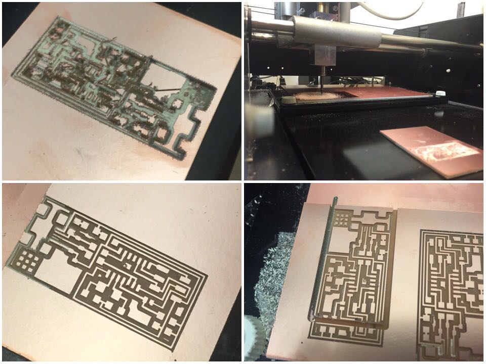
We failed four times in milling the board, after spending at least one
hour in figuring out how to make the machine move and how to change the
milling heads. It seemed like the original point never followed our instruction.
Once the file was sent, the pin (mill head) will always "jump" about 1 cm from the
resting point and then started cutting. We still have not figured out why this happen
but we decided to ignore it as long as we can get a correct board.
The first time we mistakenly used 1/32" endmill to cut the circuit board so it was a mess.
The second time the frame was too shallow and it's not removable. Third time the 1/32" endmill
jumped to a different original point and ruined the whole board. Everything went well in the
fourth time except for a bit wrong calculation for the starting point so the circus was too
close to the boarder of the board and there's no place left for the frame.
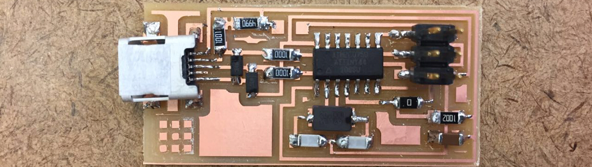
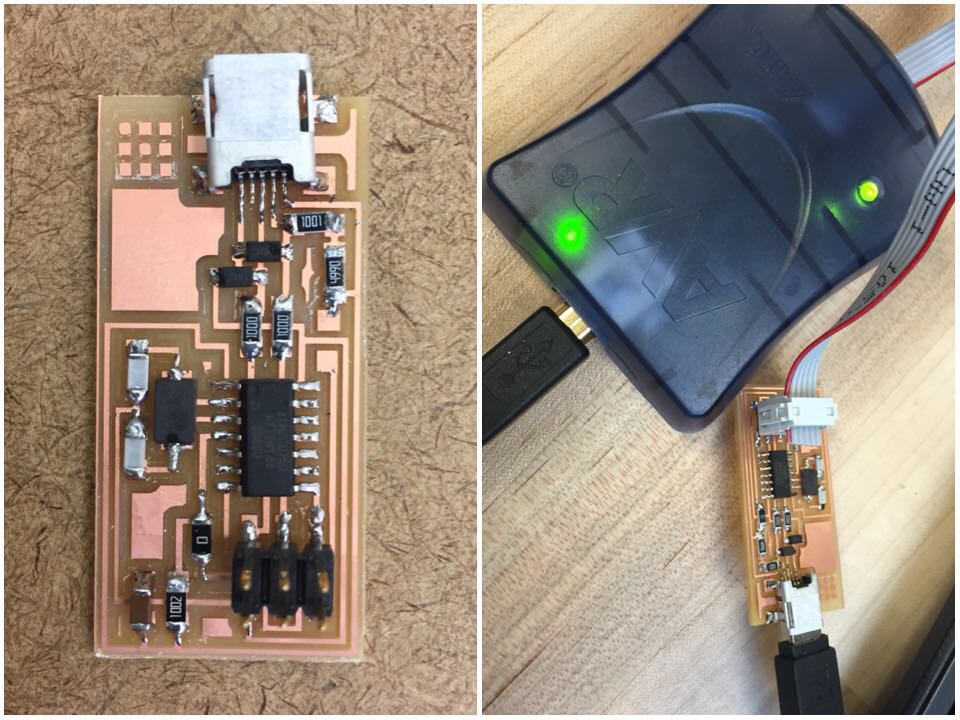
Finally we got two usable boards for each of us and we can start collecting the components and do the soldering.
I have had some previous experience in soldering so I expected this task would be a bit easier for me. It turned
out that I was totally wrong again! I have never tried to solder such tiny components onto such tiny board!
All my experience was limited to playing with the resisters that used to test on the breadboard.
So it was still a tough task.
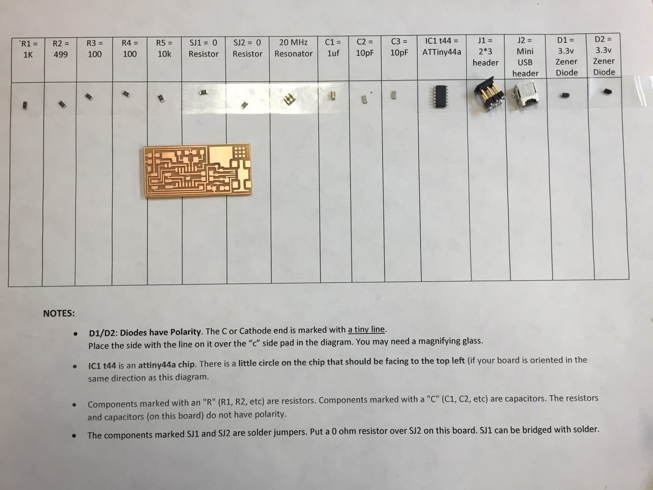
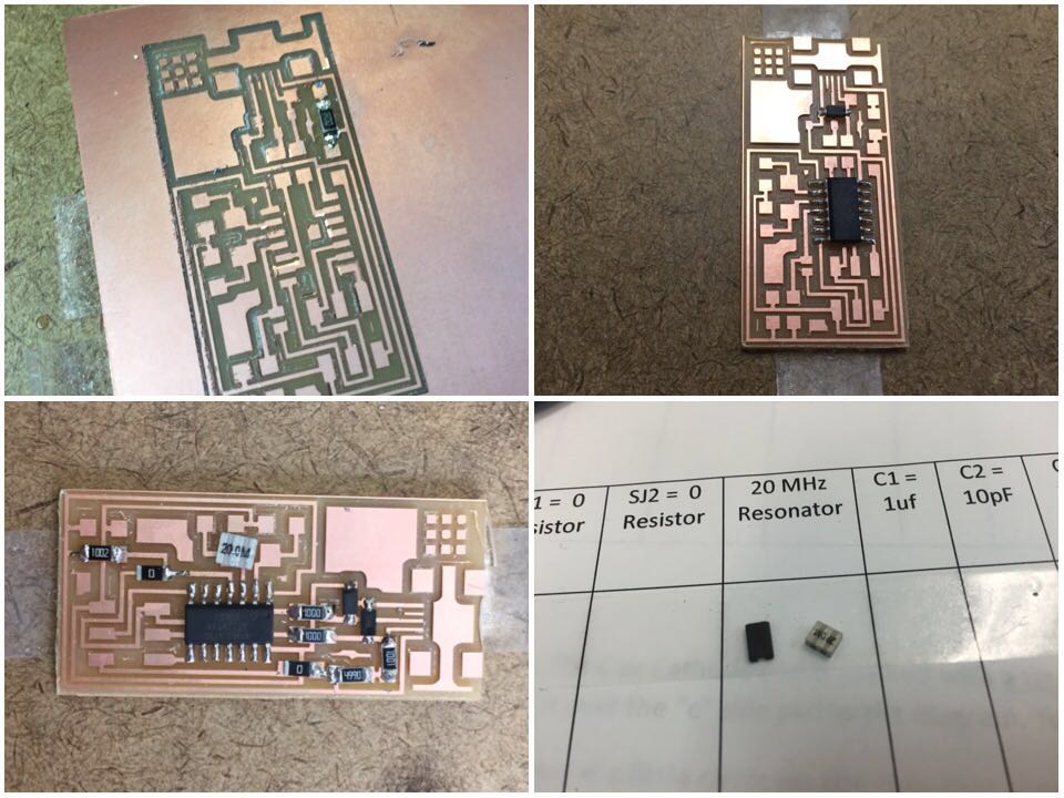
During the process I found that the 20MHz Resonator I got from the storage was
different from the one showed on the instruction photo. Then I looked it up and
realized that there are two types of 20MHz resonator: crystal and ceramics. The one
we need to use here should be crystal. It was lucky that I notice that before I fixed it onto the board.
 After hours of work, my first ready-to-be programmer finally was done!
I could not wait to test it on the computer. First, plug the micro usb in,
there was neither smoke nor burst. First mission pass, yay.
After hours of work, my first ready-to-be programmer finally was done!
I could not wait to test it on the computer. First, plug the micro usb in,
there was neither smoke nor burst. First mission pass, yay.
But when I tried to type "make clean" in the console. Error happened.
The same thing also happened on Jiamin's board and another girl's work.
So we supposed that it was the problem of the programmer or the computer
and left the shop. I was done for the day.
 Jiamin and I went back to the shop with our boards on Monday evening to finish the last step,
which is to program the programmer. Not until then did we learnt that the reason we failed on
Saturday was because we forgot to set the direction to the right folder. Anyway,
with the TA's help, Jiamin's board was successful programmed and worked perfectly.
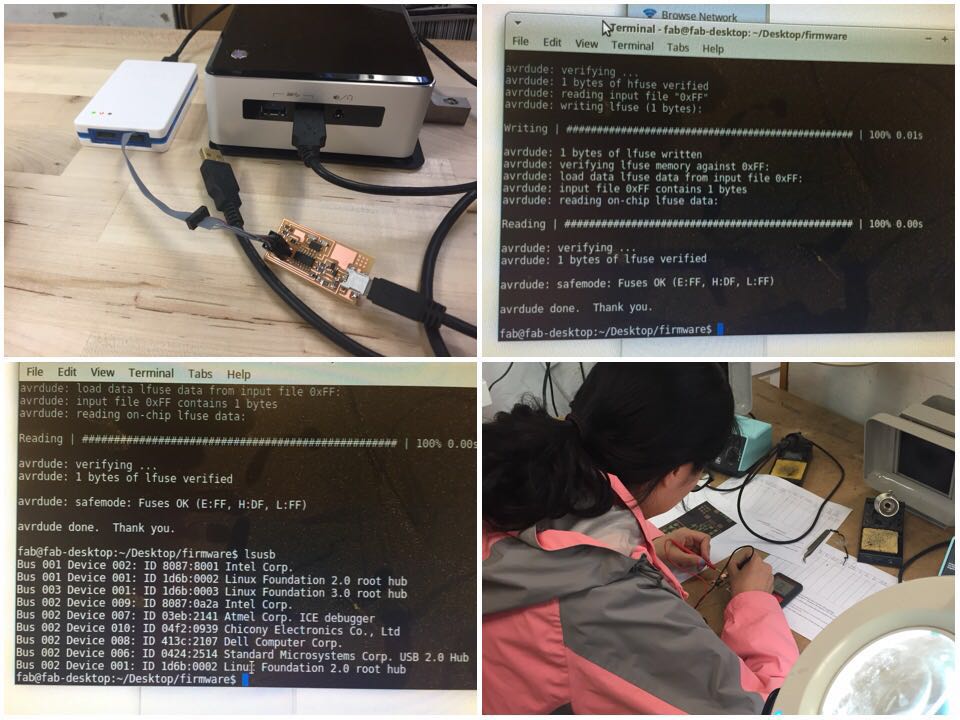
Then I was my turn. The process of programming seemed good, but the usb could not detect
my circuit board when I typed "lsusb". As instructed I checked every part of the circuit with
a multi-meter. There was no mistake in the components or the circuits and each part was linked
to the right place. However the computer just kept failing in detecting my programmer. I was
so frustrated. It was a sad story.
Jiamin and I went back to the shop with our boards on Monday evening to finish the last step,
which is to program the programmer. Not until then did we learnt that the reason we failed on
Saturday was because we forgot to set the direction to the right folder. Anyway,
with the TA's help, Jiamin's board was successful programmed and worked perfectly.
Then I was my turn. The process of programming seemed good, but the usb could not detect
my circuit board when I typed "lsusb". As instructed I checked every part of the circuit with
a multi-meter. There was no mistake in the components or the circuits and each part was linked
to the right place. However the computer just kept failing in detecting my programmer. I was
so frustrated. It was a sad story.
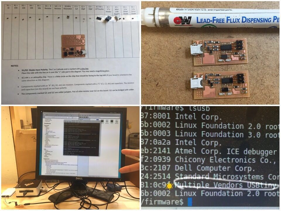 Fortunately I had a backup board left. It is always wise to save yourself with a second chance,
a plan B. So I came to shop the third time in the morning of Tuesday to conduct my plan B: solder
a new board! Having practiced on the first board, the same procedure only took me half of the time
compared to my first time. It feels great. You know what is even better? The second board worked!!
(Screaming with joy)
Fortunately I had a backup board left. It is always wise to save yourself with a second chance,
a plan B. So I came to shop the third time in the morning of Tuesday to conduct my plan B: solder
a new board! Having practiced on the first board, the same procedure only took me half of the time
compared to my first time. It feels great. You know what is even better? The second board worked!!
(Screaming with joy)
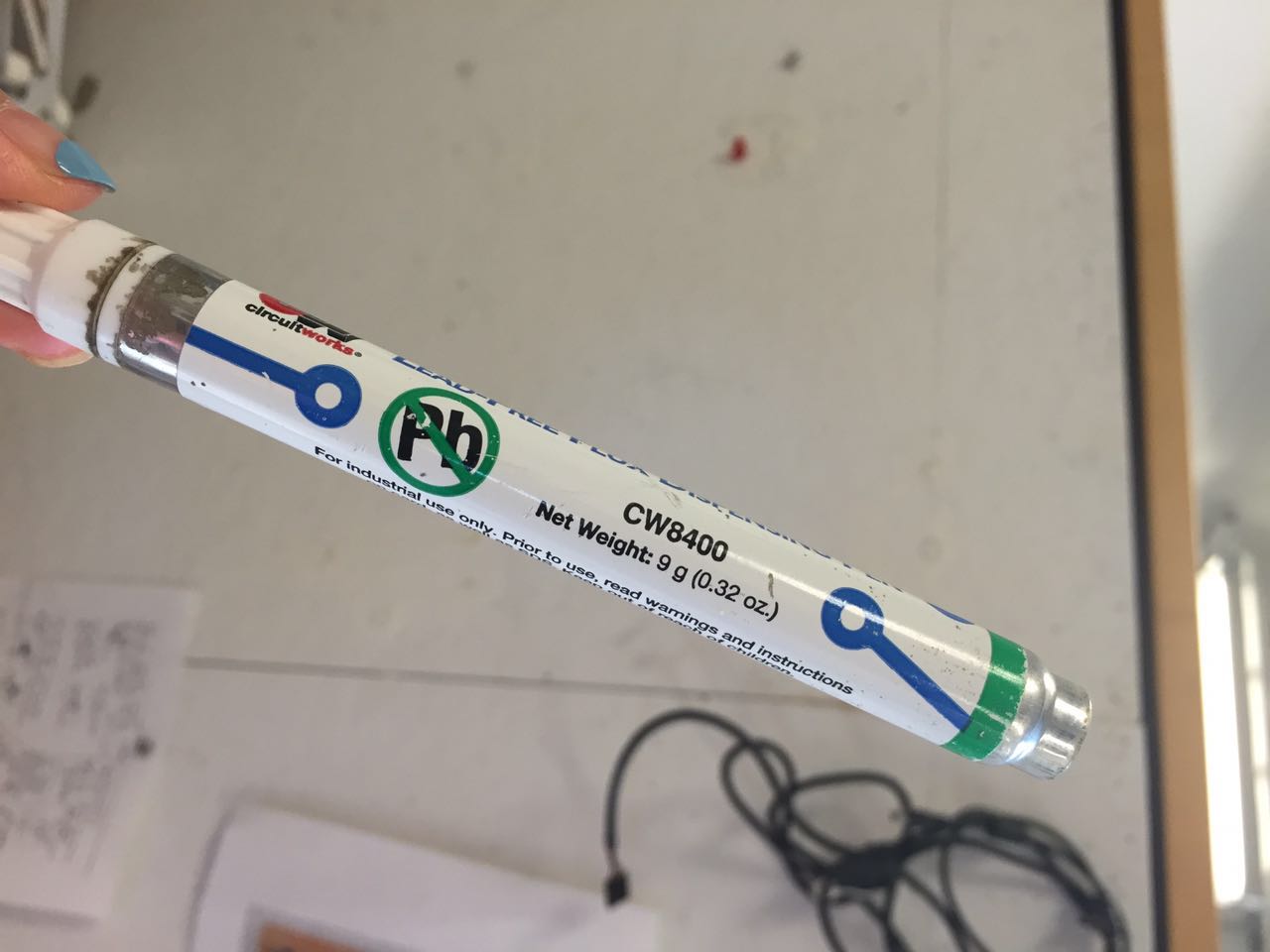
During the second soldering work I suddenly realized a possible explanation for the failure of my
first board is I did not use the lead-free flux dispensing pen before putting tin. When TA told us
that this pen will help the soldering work easier I thought it was something similar to glue.
Later when I tried it seemed like some oily stuff which did no help to hold the tiny components,
moreover it made the board more slippery and harder to keep the components stable before
I put solder the tin to one leg. So I regard it as something not necessary. Also, during Saturday
there were three people working at the desk and there were only two pens. I did not want to bother to
keep asking other's for the pen, so I just did almost all the work without using it. The solder tin was
hard to control and seemed like it would never went to the board as I wish. Thus it's possible to have
some bad joints underneath the tin, or joints that are just not as good as they seem to be.
This time I tried the pen before soldering and suddenly understood that this pen could help the tin
coming off from the solder tip to the board and component's leg! It's another reason for me to finish
the job so quickly today.
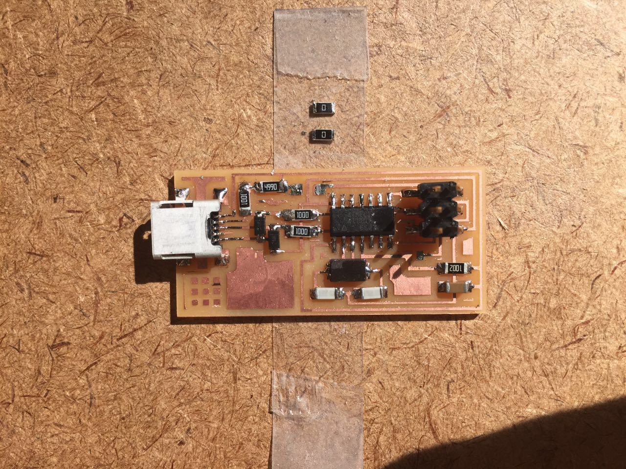
After the programmer was programmed, I removed SJ1 and SJ2 as told, and learnt an important lesson:
Follow every step exactly as the TA's instruction.
Use the lead-free flux dispensing pen when you are soldering!