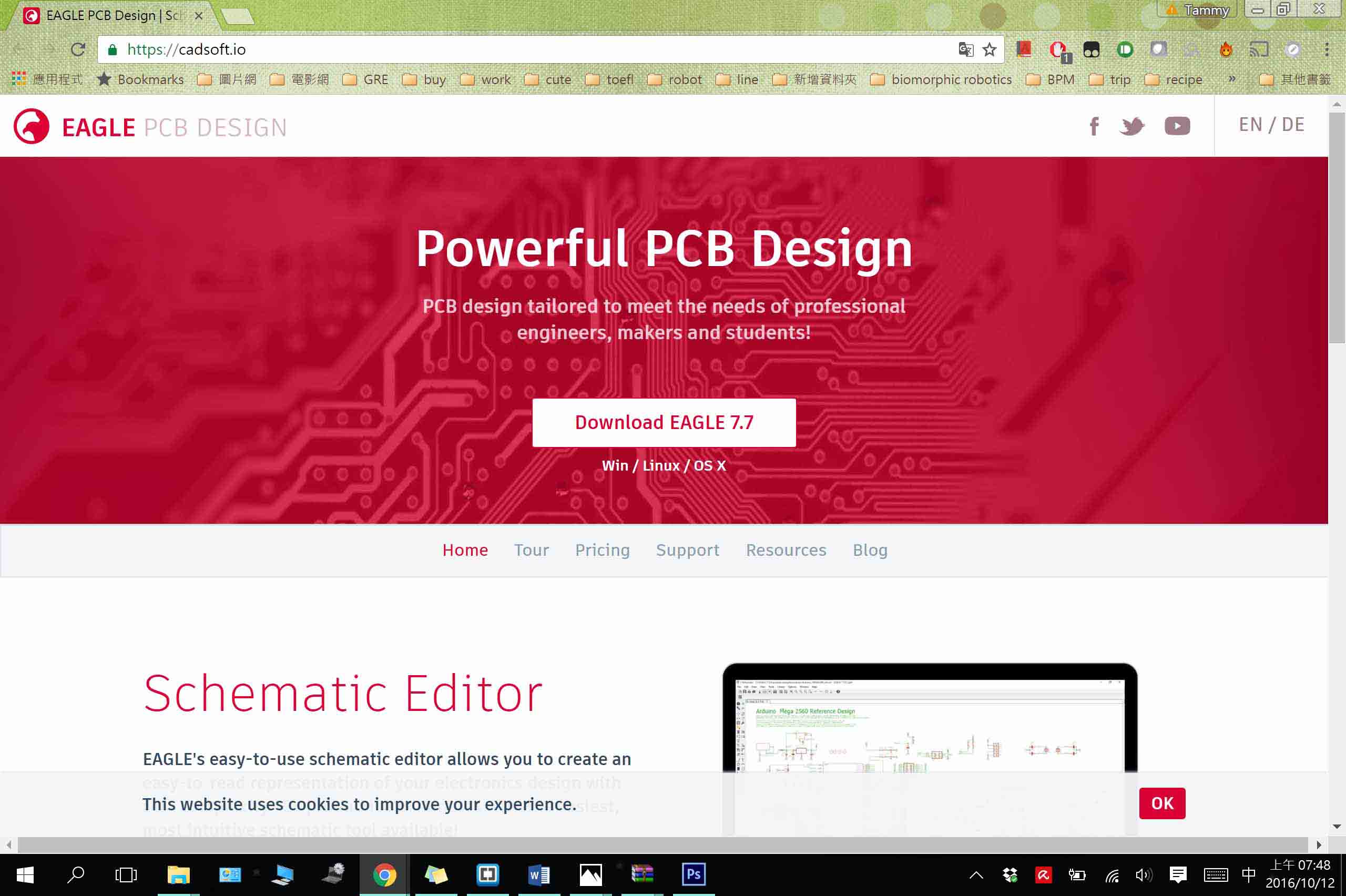
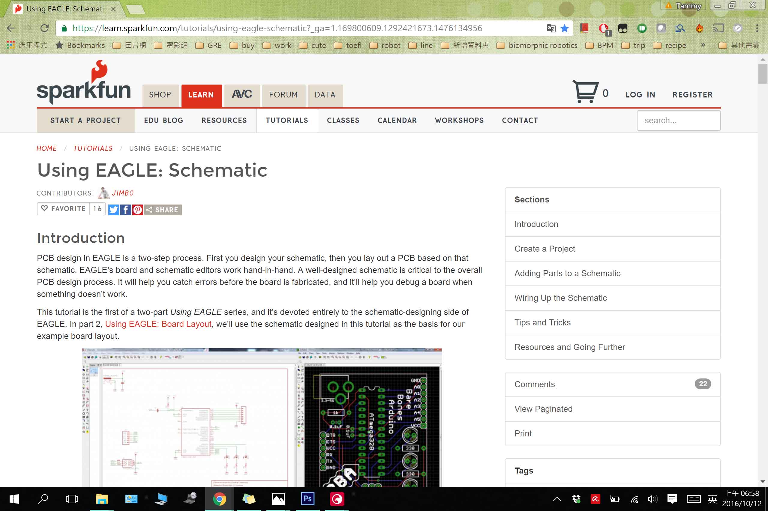
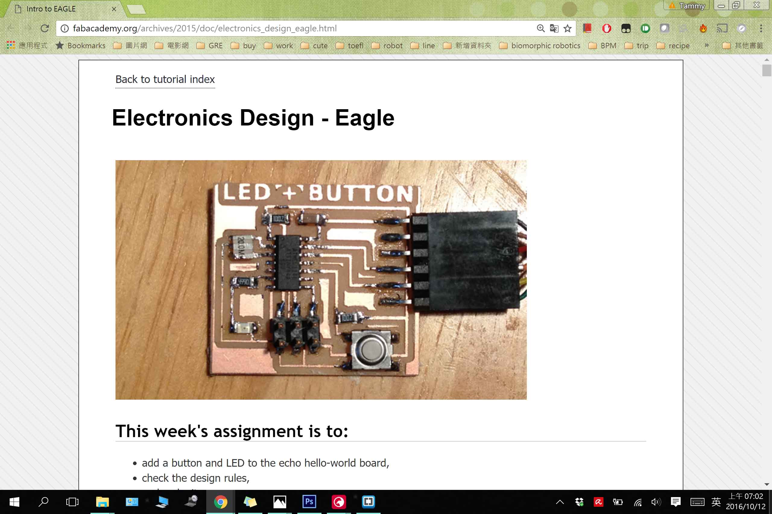
This week our mission is to design our own PCB that includes a few peripheral or interactive components (eg. a button or an LED). After designing, mill and solder the components to the board. I selected EAGLE as my software package to design the board. Before starting drawing my PCB, I did some tutrials that I found useful, including SparkFun Guide and Electronics Design - Eagle
Learn to use Eagle
*Free downloadEagle
Design my Own Board
Those are the components that was on the origninal Hello Echo Board:
● 6-pin programming header: for programming the board
● microcontroller: attiny44A. Once the microcontroller is programmed, the program stored in non-volatile memory. This means that it will remember the program.
● FTDI header: powers the board and allows board to talk to computer
● 20MHz resonator: external clock. The attiny has a 8Mhz clock but the resonator is faster (increase the clock speed of the processor) and more accurate.
There are the components that we need to add on:
● Resistor (value 10k)
Purpose: pull-up resistor.
● Button (OMERON switch)
● Ground
● VCC
● connect pin 10 (PA3) on the microcontroller to the button
● LED (Light Emitting Diode) - LEDs have polarity - the side with the line is the cathode and connects to the ground side.(see schematic below)
● Resistor (value 499 ohms)
Purpose: current limiting resistor
Why do we need a current limiting resistor? So we don't burn out the LED.
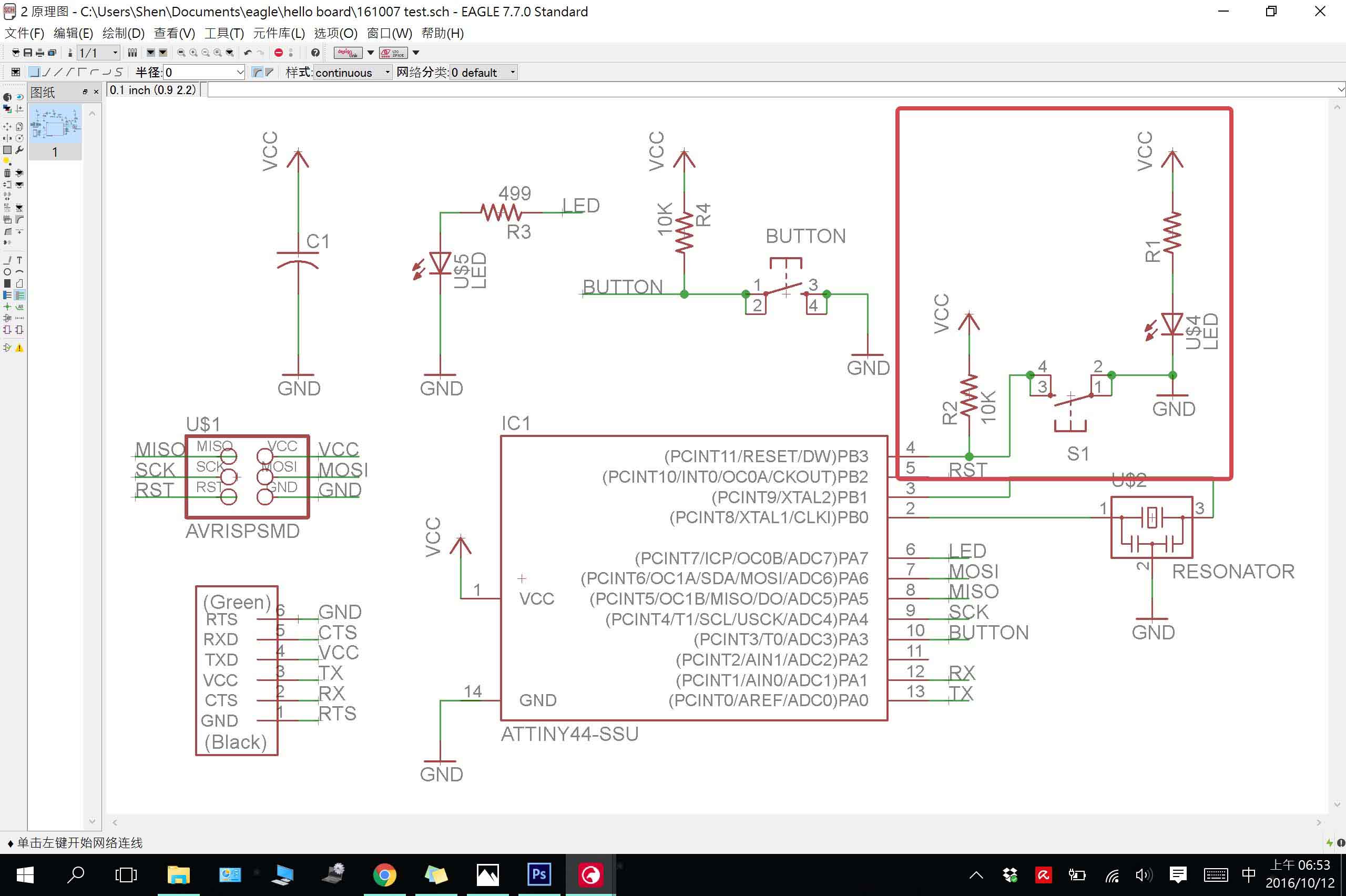
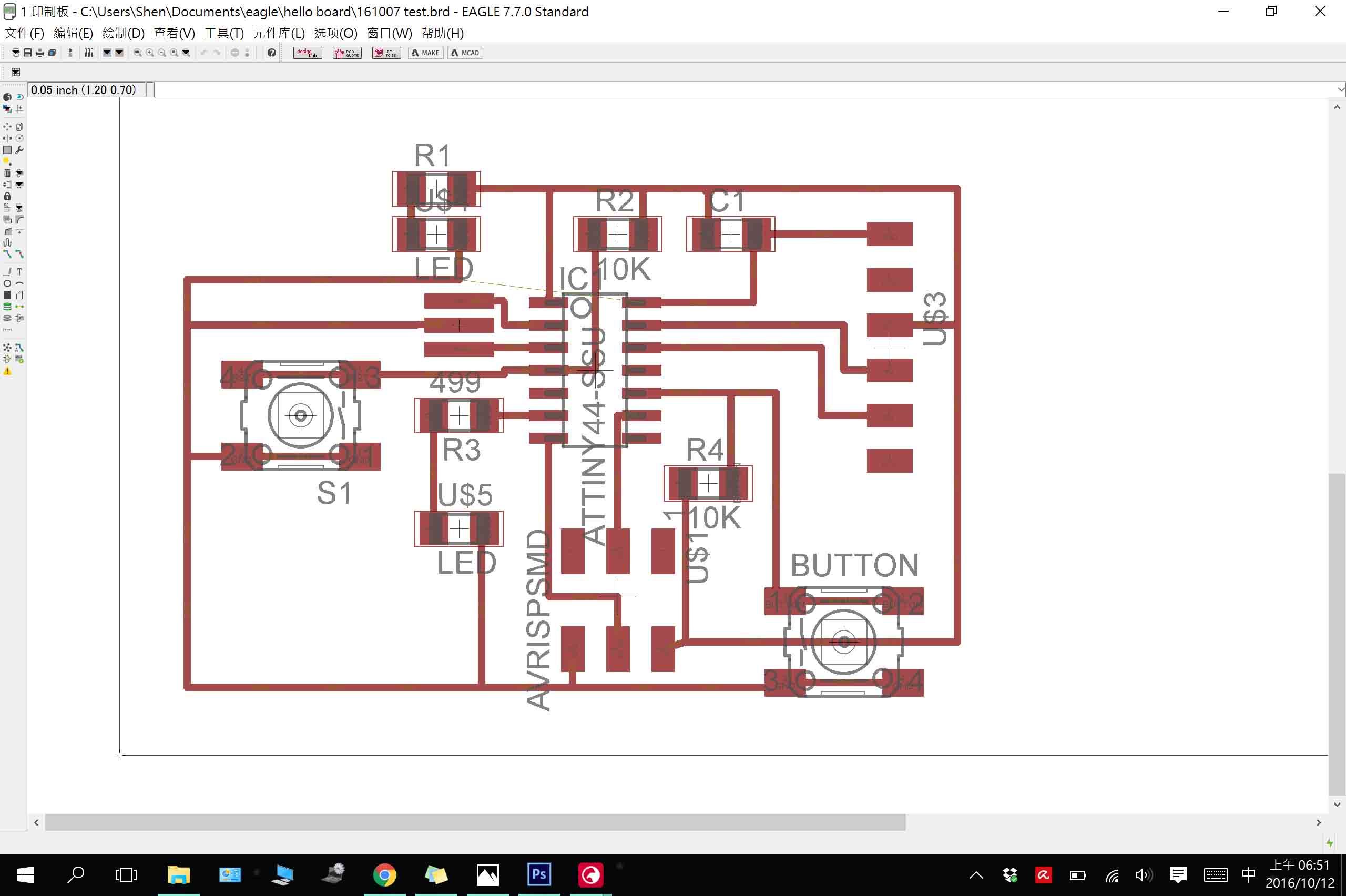
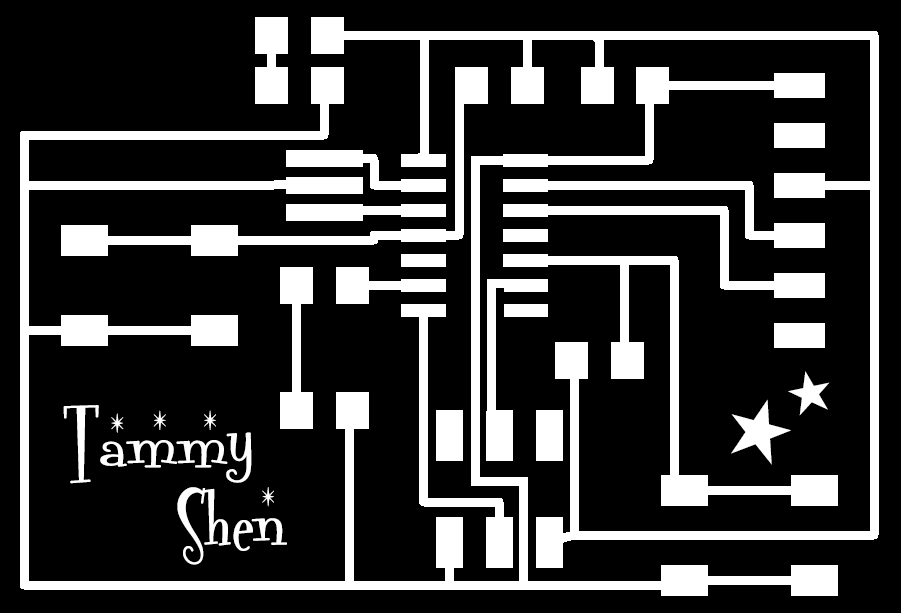
Following the turial, I made my board. However, I add one more LED to show the board is on, and a "reset" button. (The red circle on the right.)
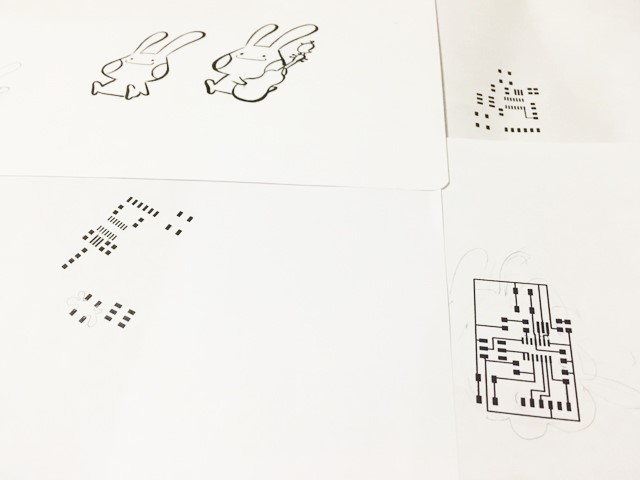
Explore it to .png file
Since there are so many beautiful PCB layouts that were made by prior students, I was also trying to made mine as a cute rabbit and did some roughly sketch on it.
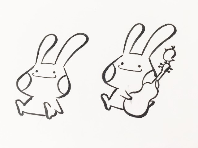
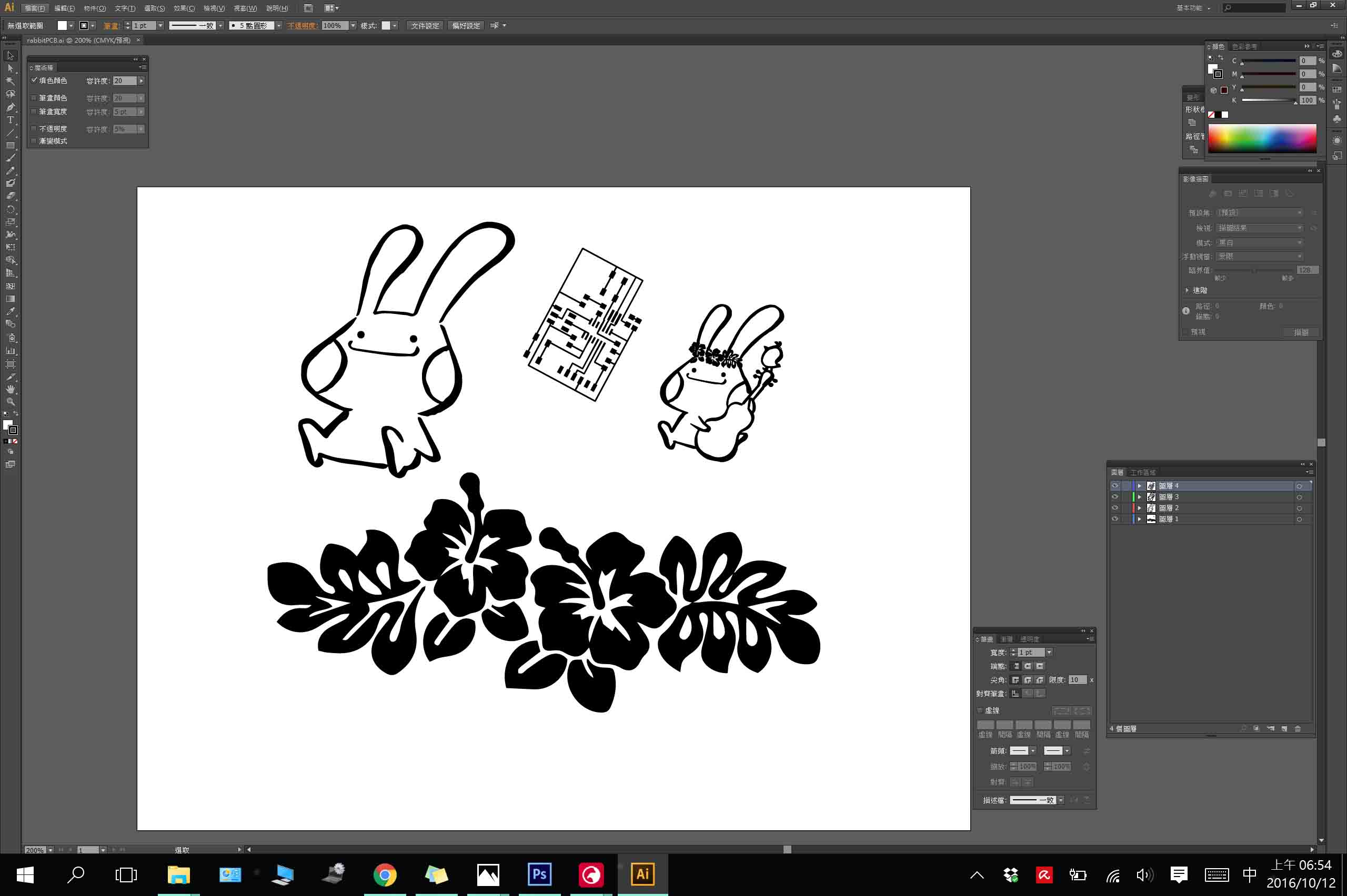
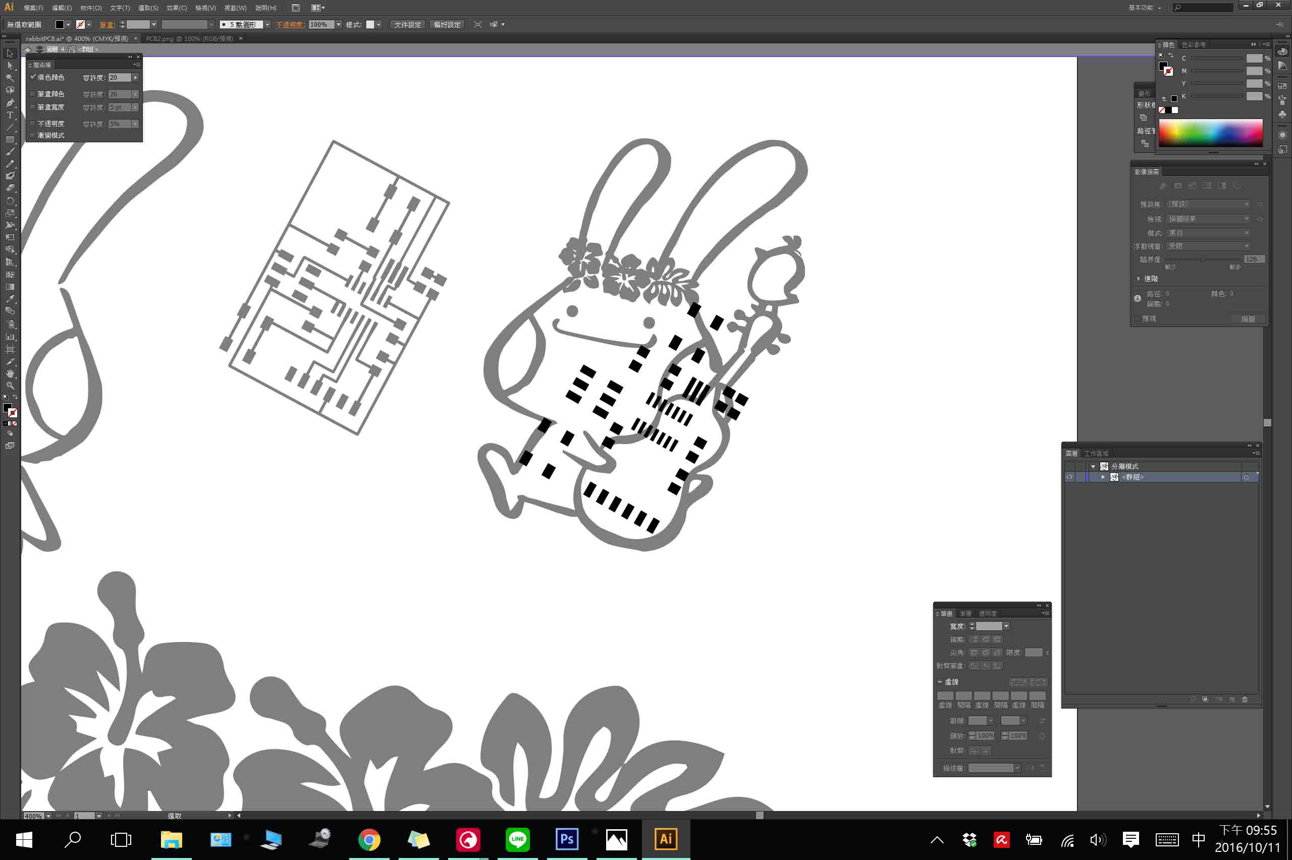
However, at the end I can't make it, so I just simply added my name on the board
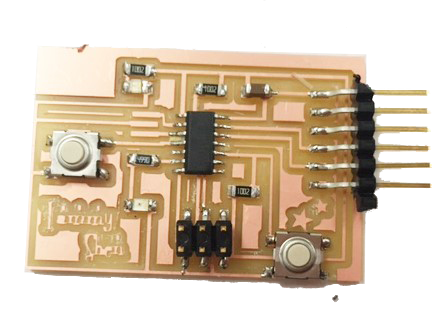
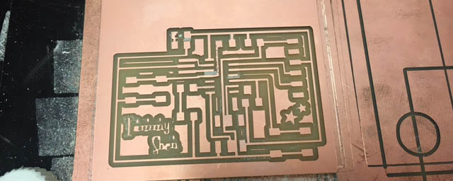
Milling & Soldering
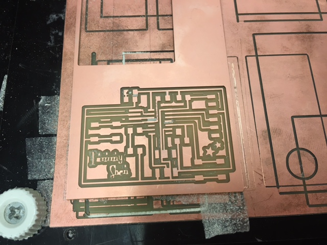
Milling the Board
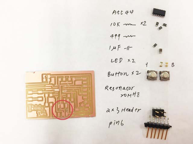
Find Components and Solder the Board
During soldering, I found that actually there are some lines (red circle) didn't milled though by the machine, so I use knife to cut though them.
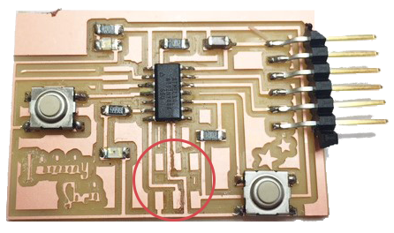
Here comes my final board!