Apnea platform: Background and Goals
- Sleep apnea causes a decrease in blood oxygen and is caused by obstructions in the sleep passages that also result in snoring sounds
- I want to have a microphone that detects snoring sounds and then actuates a pump connected to a pillow that forces me to change sleeping position by selectively inflating and deflating sections of the pillow
- In the spirit of spiral development, being able to sense the sound, do some elementary operations and then activate a motor will be satisfactory. Everything things else after this is akin to adding bells and whistles
- The bigger picture is that I want to design a modular platform that can take several input sensors (blood oxygen, snoring, breathing rate from motion sensors, etc.), perform different actions (pump pillow, vibrate, etc.) and do some advanced data processing on the fly (e.g. to detect snoring sounds from regular background noises)
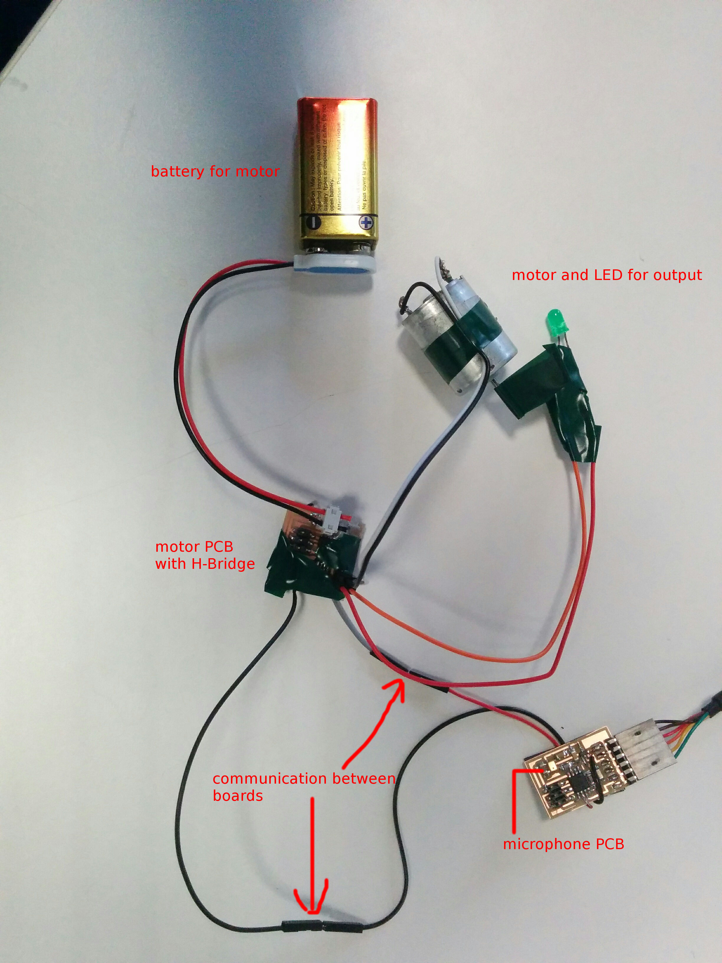
Final Circuits
These are the final circuits. The way it all works is:
- There is a PCB that records sounds and does real-time 16-point Discrete Fourier Transform to pick up snoring sounds
- This mic-PCB sends a HIGH-signal over to the motor PCB when snoring levels are above a custom threshold.
- When the motor PCB receives the HIGH signal, it powers the DC motor and LED for 2 seconds
- I was able to implement real-time FFT on the chip using some amazing code I found online (more on this later)
- The ATtiny44/5 is not powerful enough to do more than just real-time FFT. The real way to do it includes doing PCA of the frequency vector but the ATtiny44/5 does not have the memory or the speed to do it unfortunately. I tried and two problems occur:
- The size of the code does not fit in the memory (static and dynamic) of the chip. This can be solved by smarter, more efficient code to some extent
- Even if the above can be solved, computationally real-timeness degrades over time as more and more operations do not finish on time. Is there a way to quantify this problem? To know exactly how many clock cycles are being used?
- In the spirit of spiral development, now that I have FFT, communication, input and output working, the main work is done. This should make it easy to add the required stuff (a peristaltic pump instead of just a motor, inflatable multi-section pillow, PCA of FFT vectors, etc)
- Cost: minimal since I made everything from scratch. Going forward, I will be using an ATmega at the least so cost will increase but only slightly.
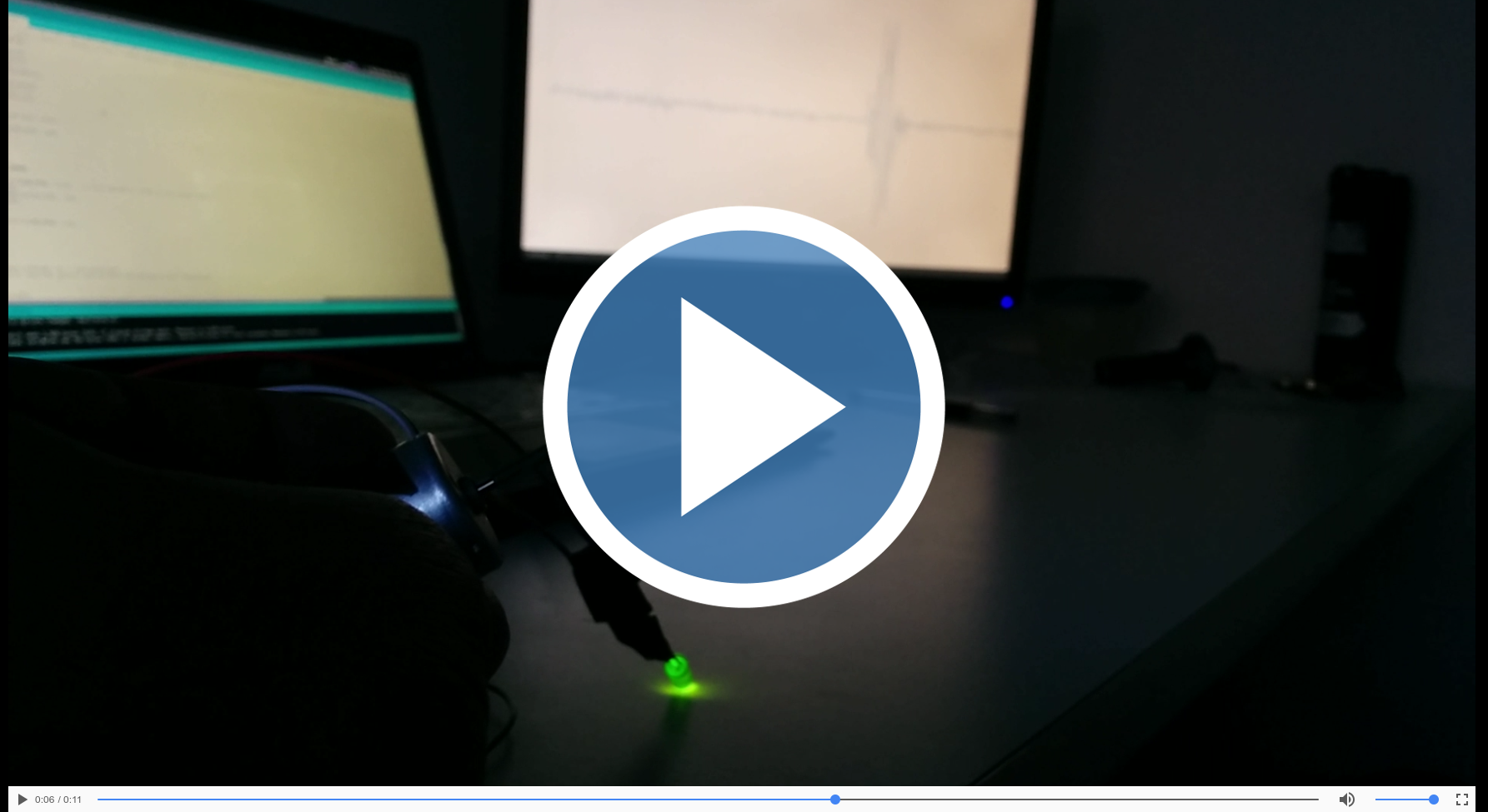
Video of the circuit in action
You can see the motor and LED triggering based on sound, with a real-time sound signal on the screen (through USB serial)
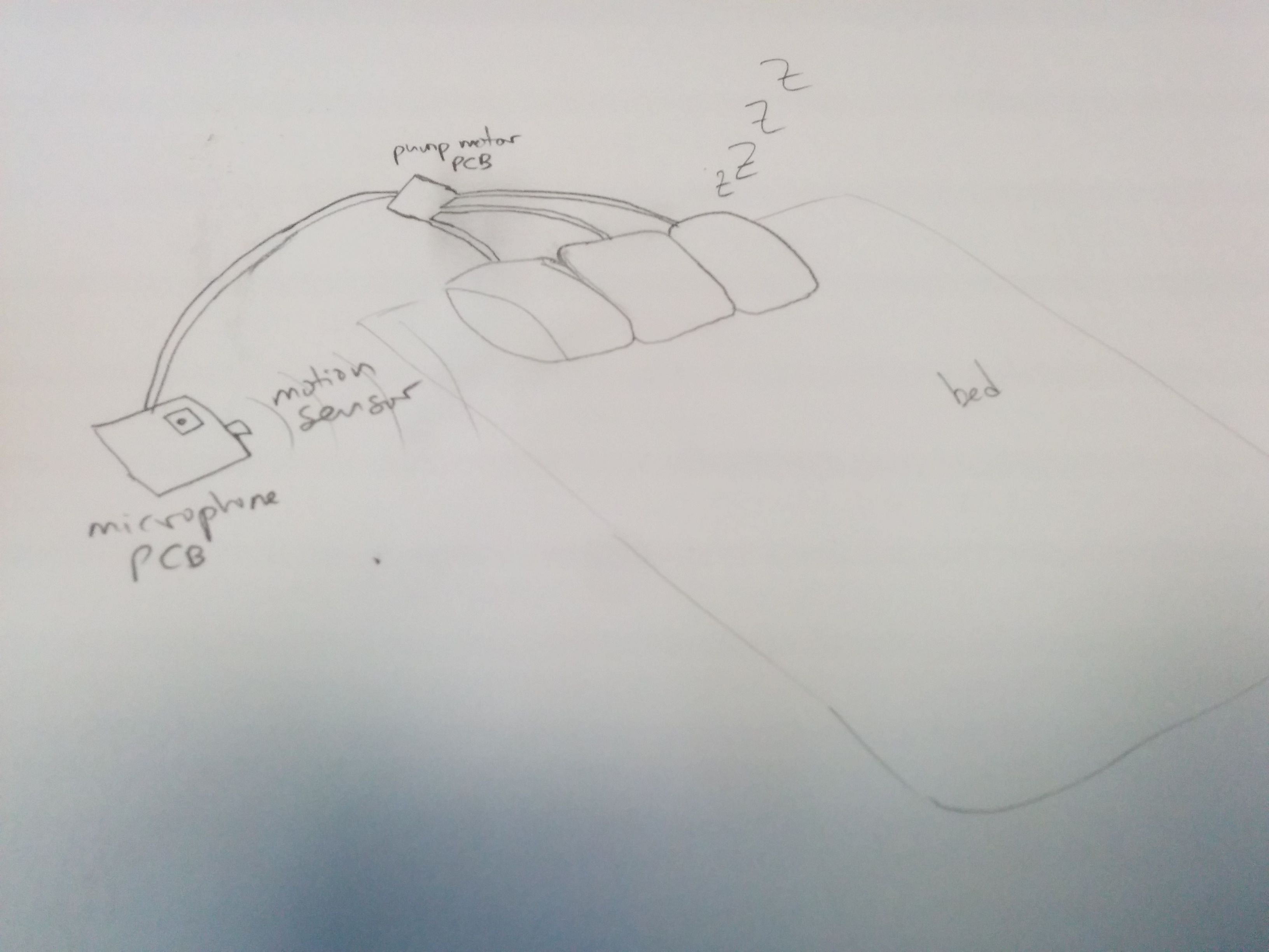
Sketch of the vision
Peristaltic pump to add
Basically a motor that can build pressure
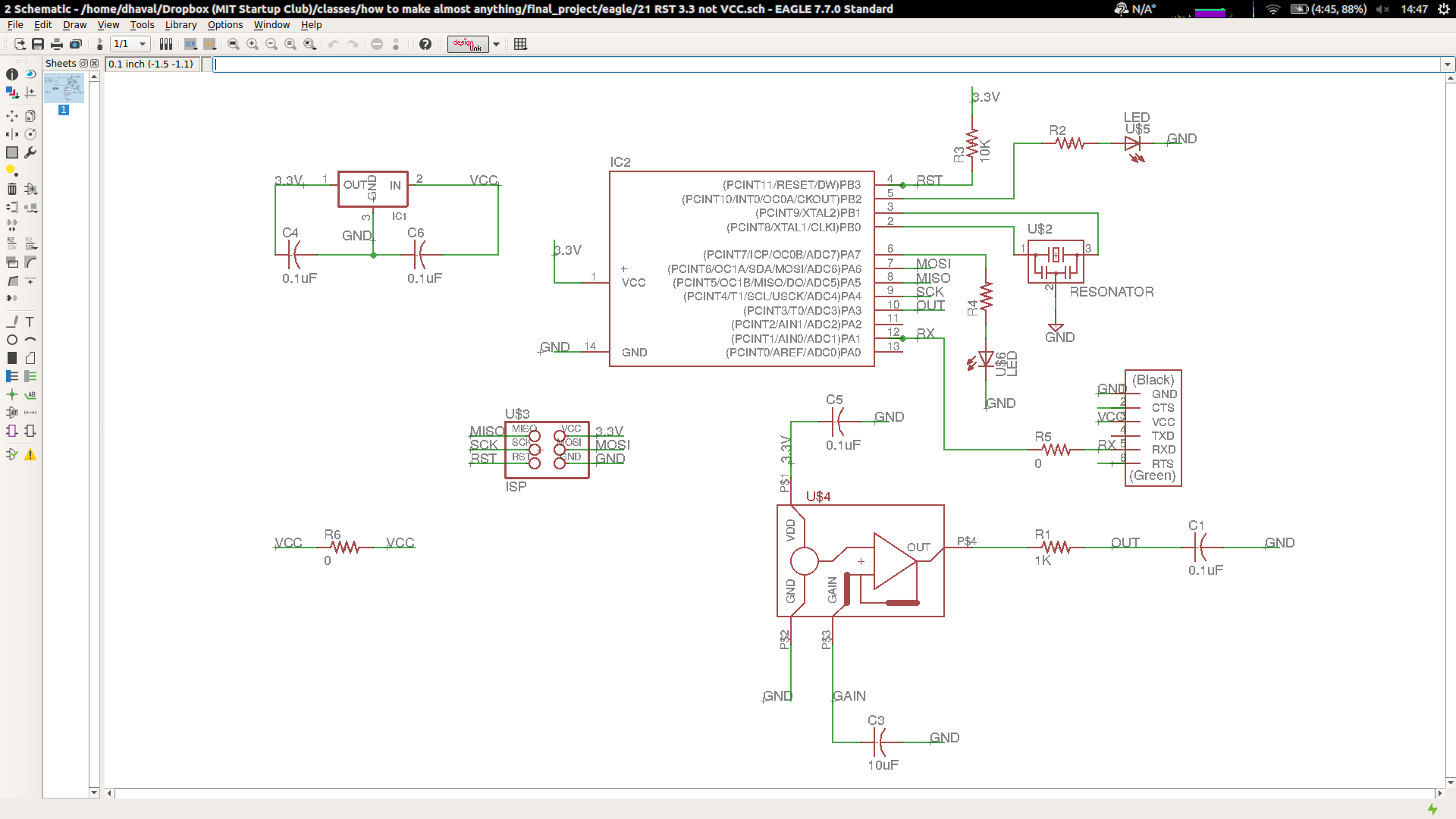
Circuit diagram
I based my circuit on Neil's analog MEMS microphone circuit, replacing the ATtiny45 with a ATtiny44. All files (Eagle circuits and code) can be downloaded here
Basic components are:- ATtiny44 for microphones and motor PCB
- H-Bridge for motor
- 3.3V regulator for microphone and 5V regulator for motor
- LEDs for debugging
- Motor, battery and USB power
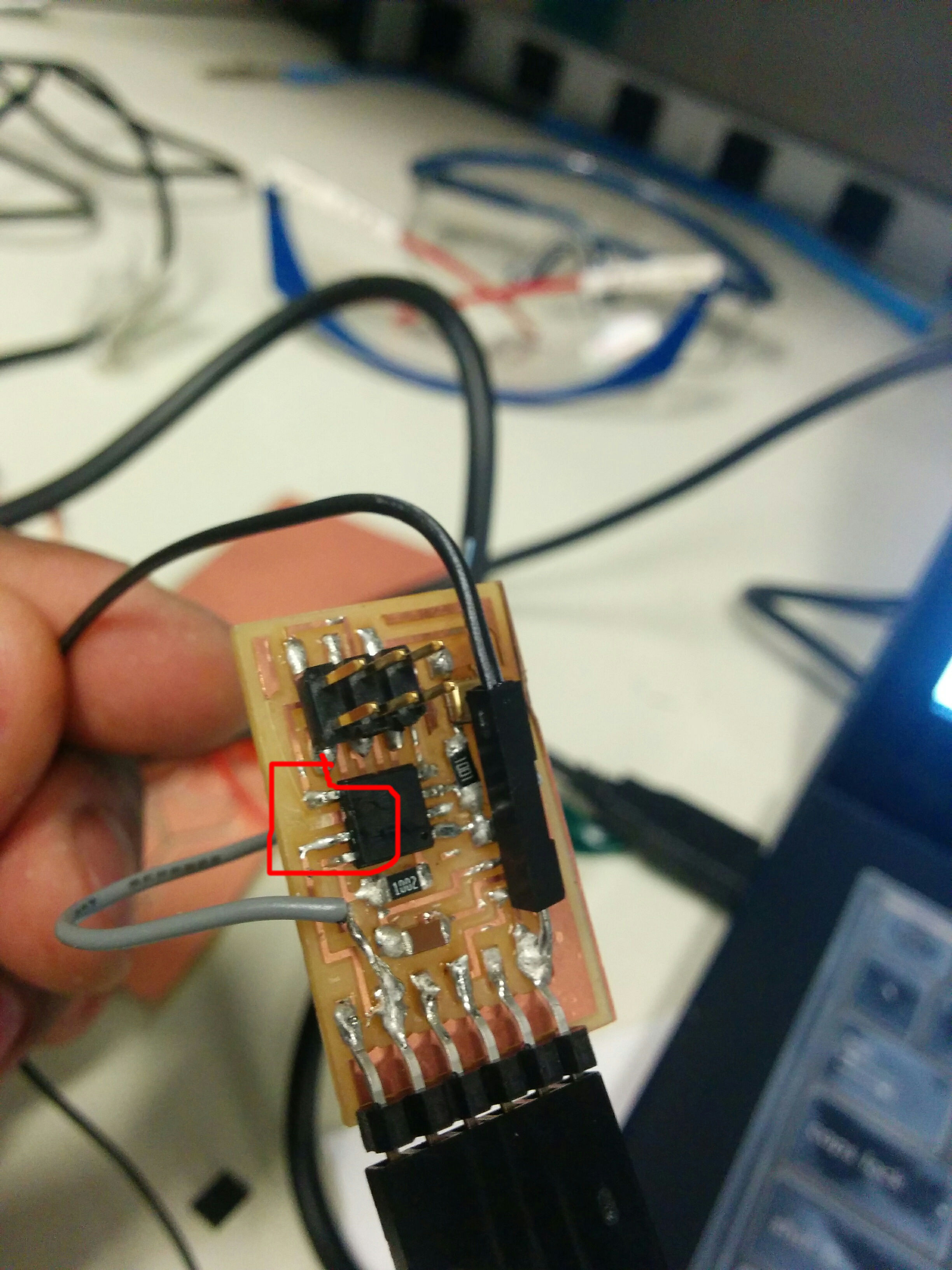
Don't solder jumpers to legs!
When I was finally done with my final circuit, I accidentally ripped one of the legs. And of course MISO was connected to this leg so I could not program the circuit anymore. So I had to remake it!
¯\_(ツ)_/¯
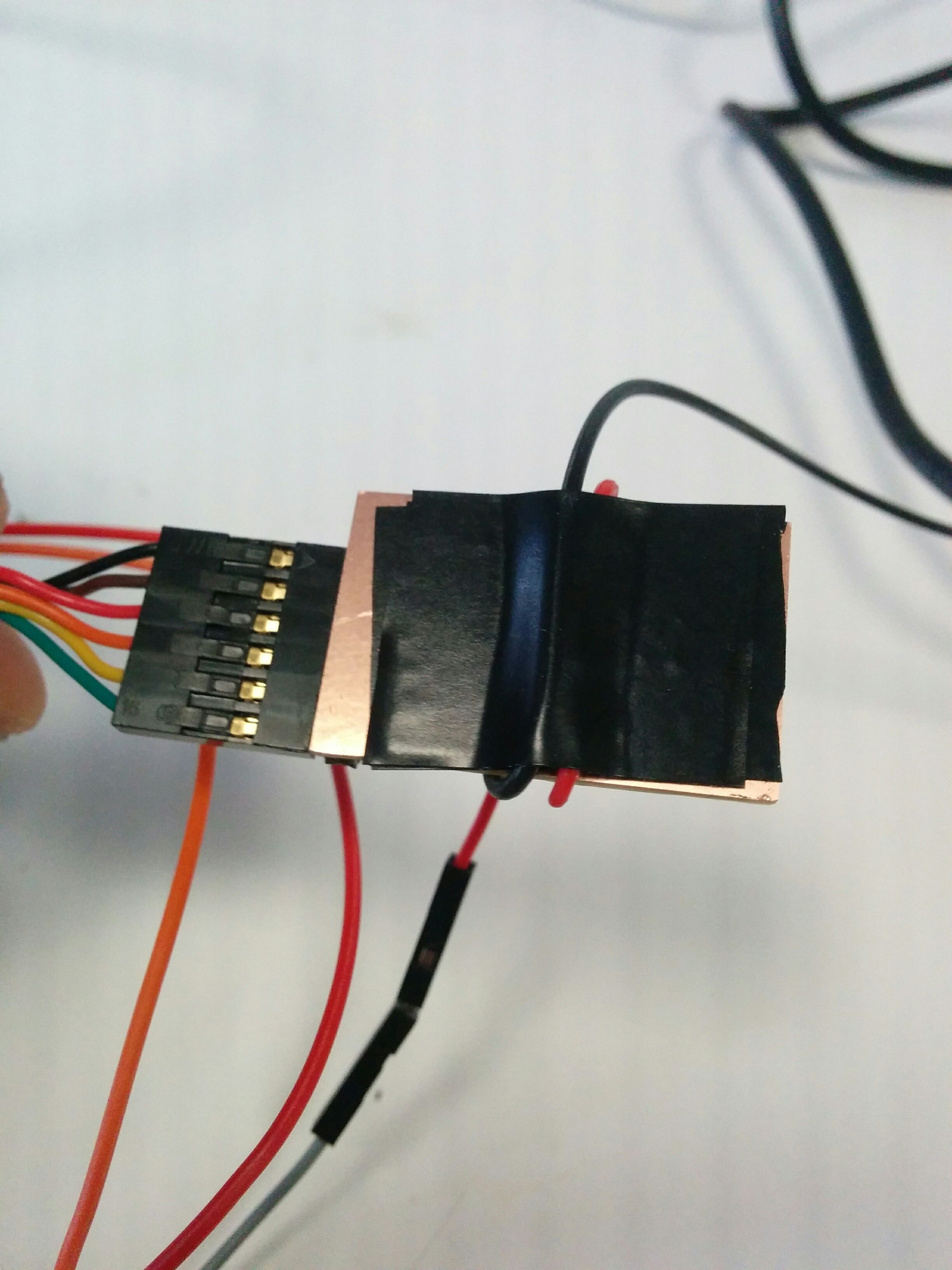
How to manage wires
Tape all your wires so they don't wiggle in the back
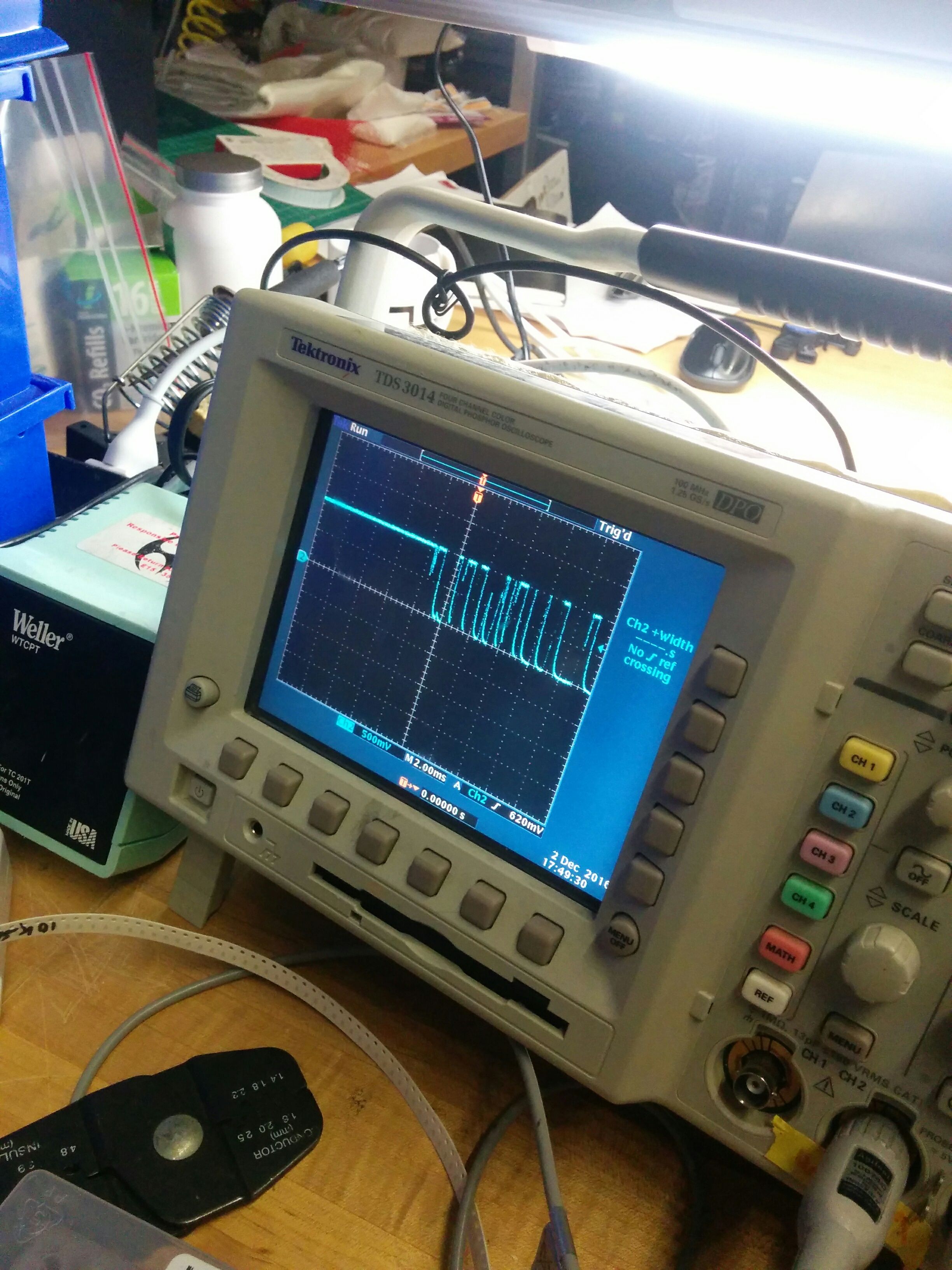
Mic checking
For a while my microphone was not responding. I didn't know if it was the chip or the circuit so I used an oscilloscope and found out there was something wrong with the trace/solder
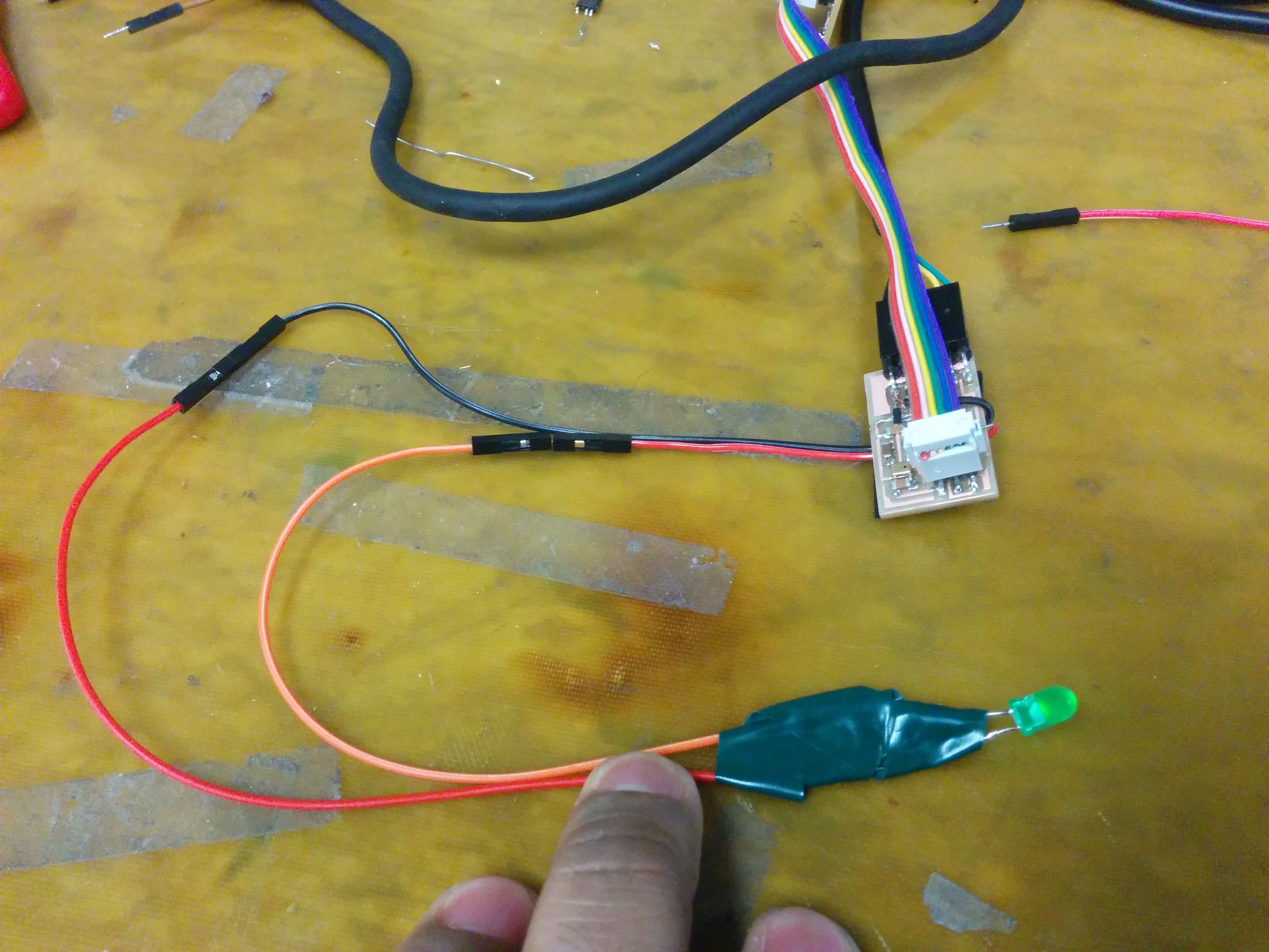
LED debugging jumper
I was a bit frustrated not being able to get debugging feedback form the circuit so I made this LED jumper and it was very helpful!
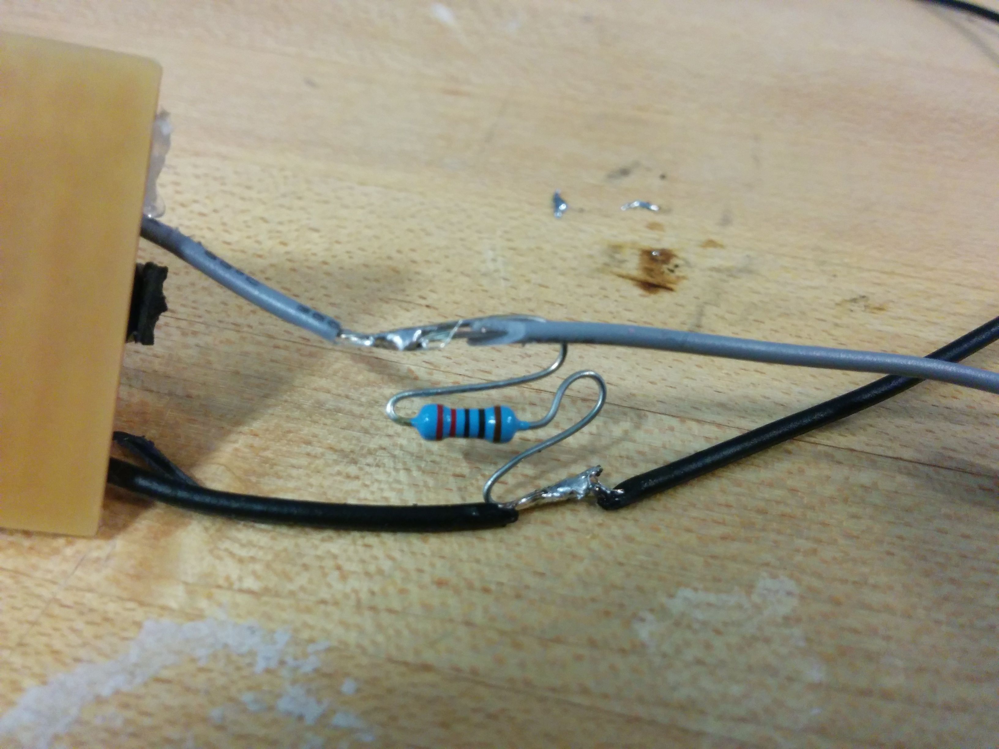
Air wires are bad
One of the problems I had when trying to communicate between the chips was that somethings when there was no signal from the mic-PCB the receiving PCB would act strange. Finally, I realized it was because there was not default low-voltage on the communicating wire so I added a resistor to make it a default 0V when there was no input from the MIC-transmitting circuit
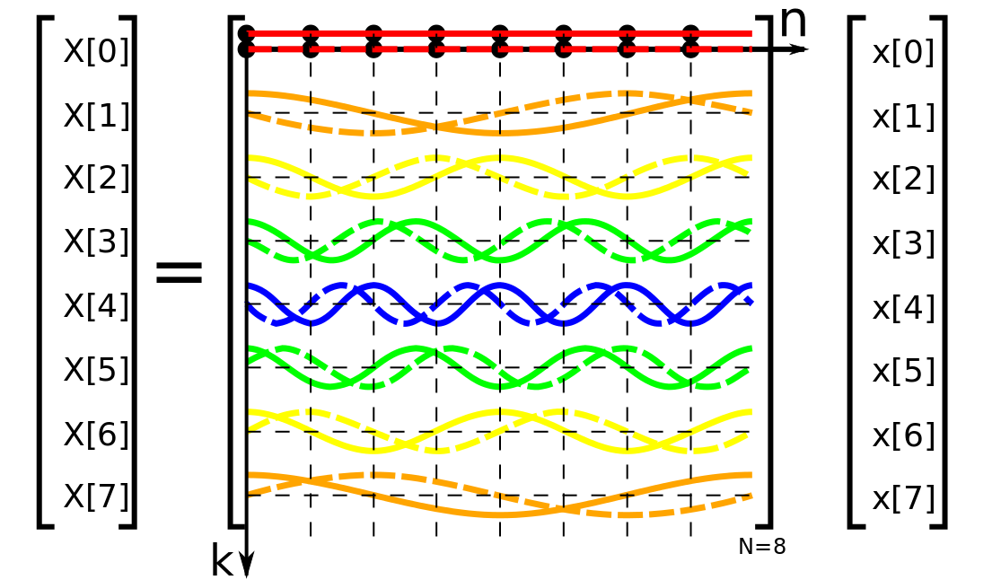
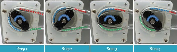
16-point DFT
One of the main things I had to do for the microphone circuit was to do real-time FFT. I finally settled on this algorithm that does 16-point Discrete Fourier Transform. The picture (from Wikipedia) shows an 8-point DFT matrix: the X[0] value represents the constant DC signal, and the other X values represent the FFT values. I was able to implement this in real time. The code I used is from here!

Final goal
The best way to detect snoring is from this paper, 'An efficient method for snore/non-snore classification of sleep sounds', which runs FFT on the sound, does an eigenvector projection and then runs a classification on the data to see if it is snoring or not. The chip could only do up to FFT in real-time. I tried to do more, but the cycles would start being delayed and things would get out of whack.
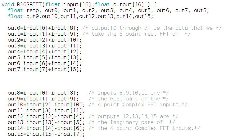
16-Point DFT algorithm
It is really interesting how the DFT is implemented as a series of binary operations to be fully efficient!
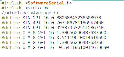
Speed!
The code hard-codes the values of several constants to be faster
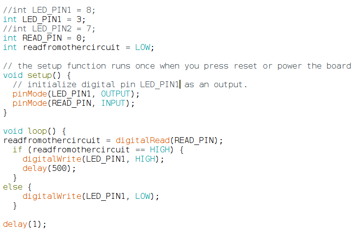
Code running on motor circuit
It is very simple: if it detects a HIGH from the mic-PCB, it triggers the motor. Going forward, I would also implement PWM on the motor to pump air into the pillow at different speeds. Also right now I have the simplest communication protocol: send a HIGH or nothing, but I could easily also implement a serial communication
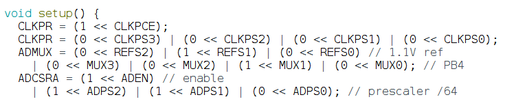
Making sound reading fast!
In order to read very quickly from the microphone, I wrote directly from and to the registers. It was fun/painful to understand how to do this.
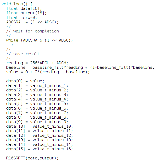
Creating timeseries
First, as you can see I read directly from the ADC registers for fast reading. Then I store the past 16 values of the ADC signal into an array called data. This array data is what the DFT function R16SRFFT runs on
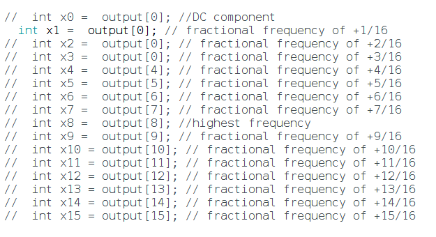
Reading the DFT output
These are the DFT outputs. Unfortunately reading from more than 1 value caused the code to take too long so it could not run in real time anymore. I am not sure what is going on.. Why would reading from more than 1 array value make the code take more time?
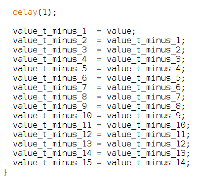
How time samples are created
This is now I implement creating 16-time samples from the mic. I also smooth these values to remove random spikes/noise
Video of the circuit in action
You can see the motor and LED triggering based on sound, with a real-time sound signal on the screen (through USB serial)