Insights from Input devices week:
- Using C is very hard. It's faster but it seems to require so much knowledge of how to use all the registers. I spent the week only using C and got it to work but it was a huge pain. I did everything in 5 lines in Arduino
- Speech freuency can go up to about 10 kHz - this requires a pretty fast chip to be able to sample, do pattern recognition, etc in real time. I don't know if Arduino is fast enough
- I think that what I will do is rapidly prototype in Arduino, get something working and then later convert to C.
- The big problem I have found and will have to look into solving is how to identify breathing/snoring sound frequencies. Neil suggested that such sounds would be limited to a finite frequency window but it looks like snoring is over a large frequency window and could be more easily identified by the choppiness of the sound, than by the frequency of it
- A quick google search suggests that there are established ways to identify snoring, so now I just hope I can implement them in the chip in real-time: Paper 1 and Paper 2
Apnea platform:
I decided not to do the drone for this class because it might be too complex as a class project. Instead I will be designing a platform for taking various inputs and outputs for Sleep Apnea
- Sleep apnea causes a decrease in blood oxygen and I want to sense this. Either by building one, or buying parts for one
- Also, apnea can be detected from snoring - so I want to have a microphone that detects snoring sounds
- If apnea is happening, there are a few solutions. The less intrusive one involves encouraging the person to change position without waking them up (one of the big problems with apnea is that it prevents people from reaching the REM and deep sleep states and thus causes them to have sleepiness and -long term -deeper neurological problems during the day). This encouragement to change position can be caused by inflating a pillow to force them to move their head, etc
- Down the line, perhaps I can wire this to an air pump that blows air into the patient to open their air passages
- The bigger picture is that I want to design a modular platform that can take several input sensors (blood oxygen, snoring, breathing rate from motion sensors, etc), perform different actions (pump pillow, vibrate, etc) and do some advanced data processing on the fly (e.g. to detect snoring sounds from regular background noises)
Final Product
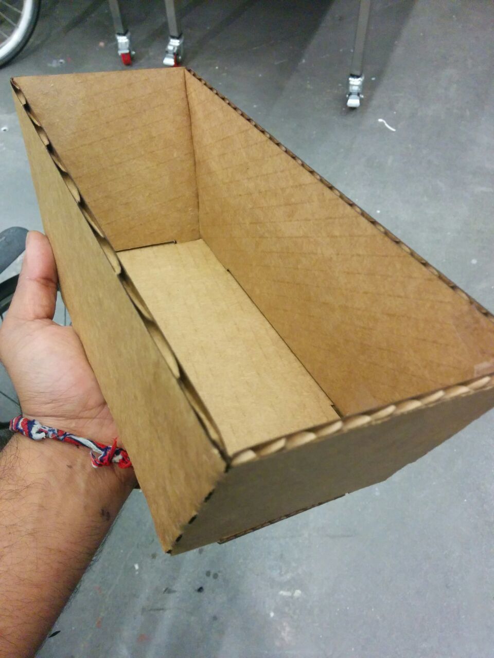
I wanted to plant herbs in my appartment but the cheap trays you can buy (~$10) are not deep enough. The trays are are deep enough are expensive (>$30) so I decided to make my own. I wanted to make one using with as few edges to connect and instead take advantage of the fact that the cardboard can naturally be folded. I plan to line the planter with a plastic sheet/bag before putting in the soil
Open questions:
> How to make parts change parametrically in solidworks (I learned how to create global paramters but what I mean is how to change one part and have copies of this part change everywhere?
> How do I make something as an assembly of parts, and export it as one 'fused' part STL?
> How to not use 123D Make (i.e. given a 3D part, how to export to 'panes' to lasercut?
> I tried using antimony to create parts. Couldn't figure it out..
Solidworks hell
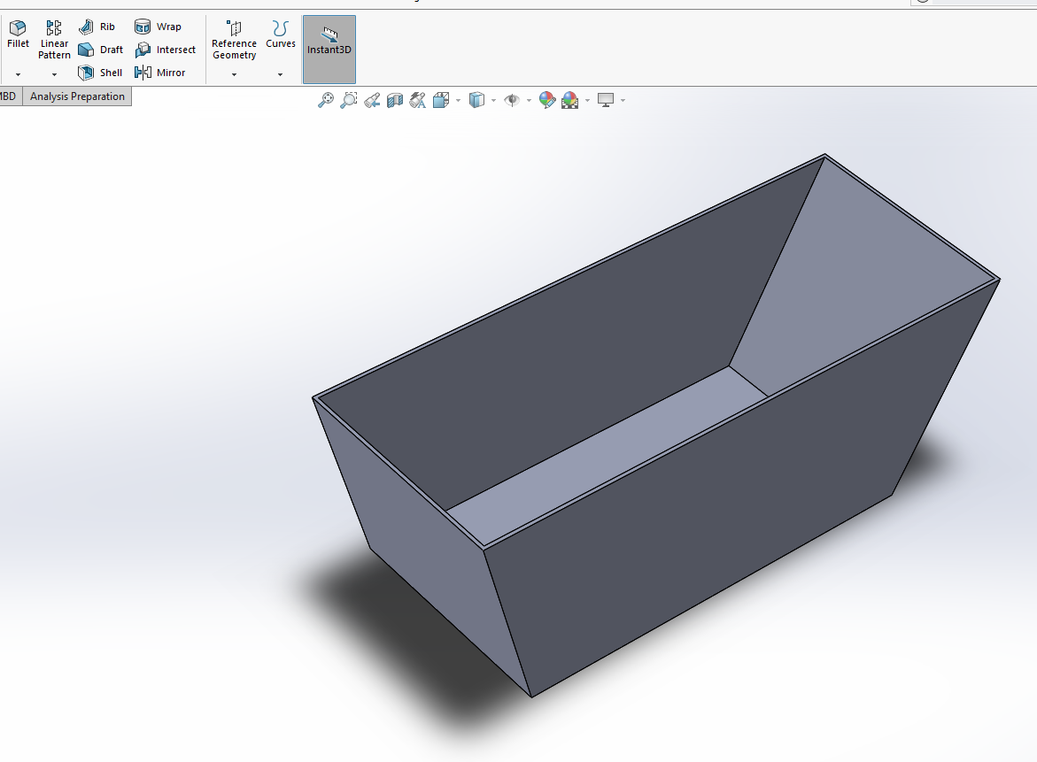
It took me a long time to understand how to think in solidworks-world. At first I tried to build the planter by designing each individual pane as a part and then putting it together into an assembly. This approach did not work because I could not get the parts to fit and because it didn't export nicely to an STL (pane below). Eventually I realized that it's simpler (in Solidworks universe) to design the front face, extrude it and then "shell" it. This gave the result you can see.
Weirdness in exporting
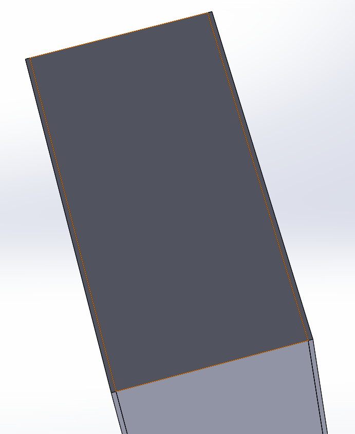
When I exported a 'fused' assembly from solidworks into 123D Make (for it to unfold the design), there was some weirdness in the import. As you can see the panes did not fit together tight like they did in solidworks, and the panes have weird thiness at the corner closest to you. This was not from a flaw in the design: I tried everything in could in solidworks to make it export/import correctly but it did not work. Finally, the extrude/pane/single-part approach did work though
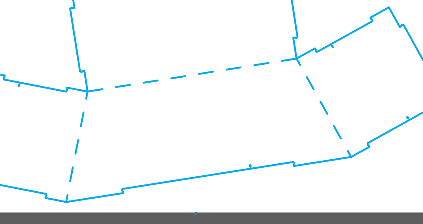
Correct import into 123D Make
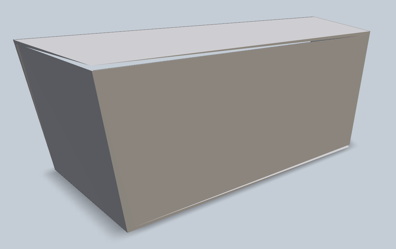
As you can see, the extrude/pane/simple-part method did finally import correctly into 123D make
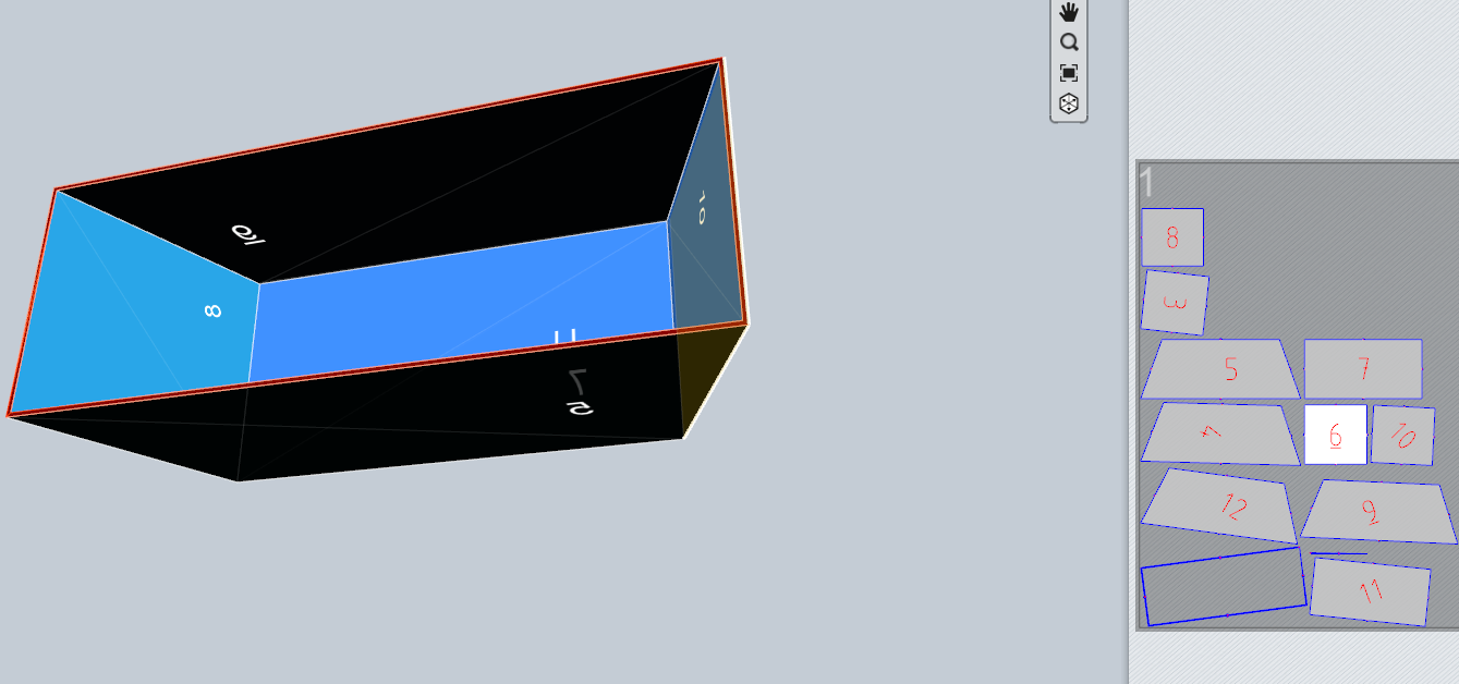
123D Make View
Although I made the part in solidworks have the minimum thickness possible, somehow 12dMake decided that my planter had to have an inside and outside planter. Each face is actually made up of two pieces of cardboard instead of 1. I tried for a while to figure out how to make it know that, for example, faces 7 and 5 should not be two faces but in vain. Eventually, I just exported the output panes to Illustrator, deleted the extra faces and then printed them.
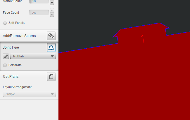
Joint
123D make offers many different joints/tenons for joining the faces. First, I chose this one (the multi-tab but the pointy parts broke too easily so I switched to one with smoother points (the puzzle)
Weird artifacts
After exporting to Illustrator from Solidworks, there were some weird artifacts. There were some random blue circles inside the panes (no idea from where). Also for some reason, exporting to EPS from 123D made each line appear twice on top of each other. Exporting to SVG did not have this double line problem (which I was told could cause the laser to cause a fire from cutting the same path twice)
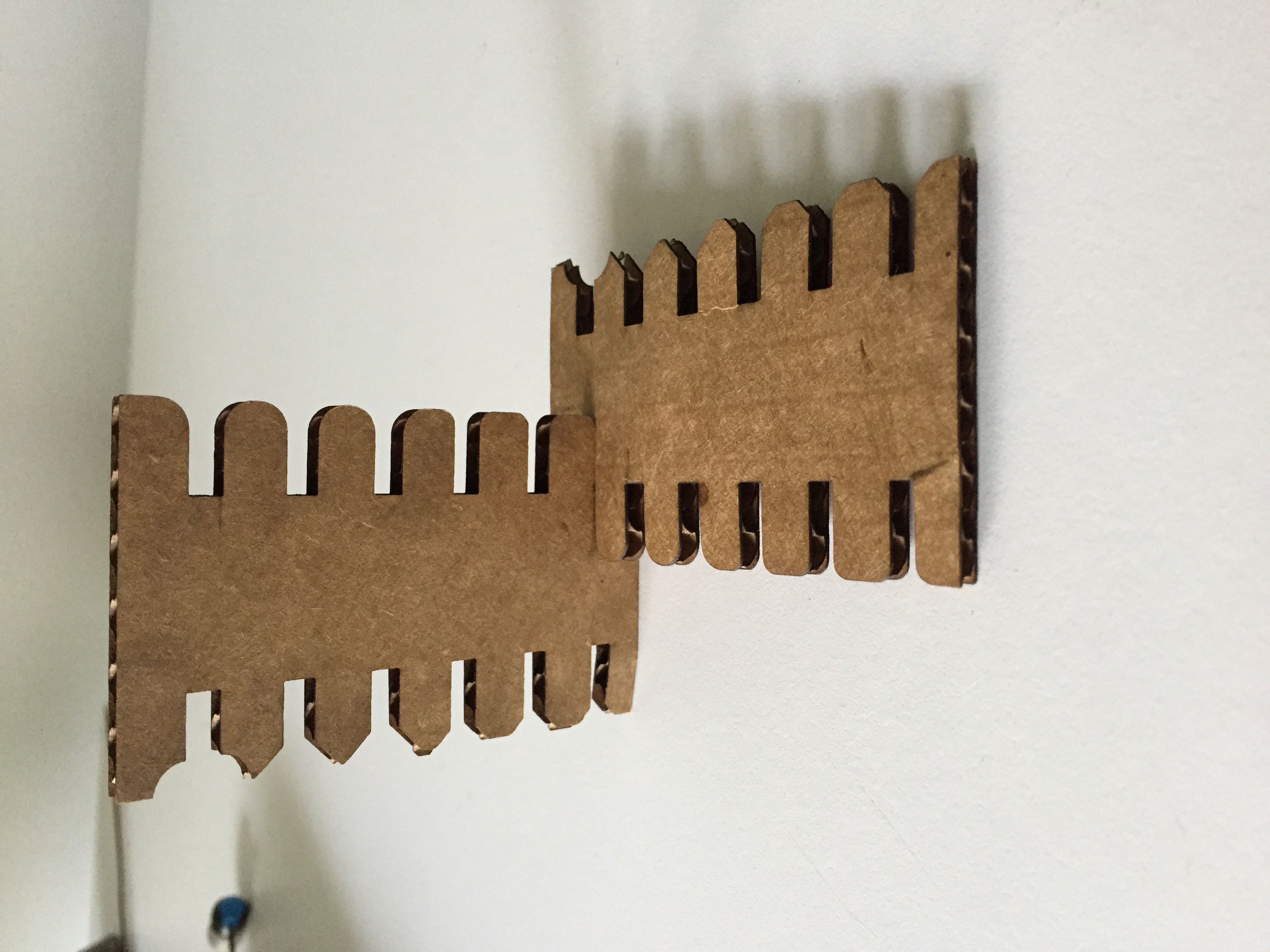
Slot testing
We tried testing different sizes and shapes of slots. The fillet really helped and interestingly the best fit slot was thinner
PANDAAA sticker
I learned to transform panda-pixels into panda-vector. I found out that you have to remove the path around the white zones.
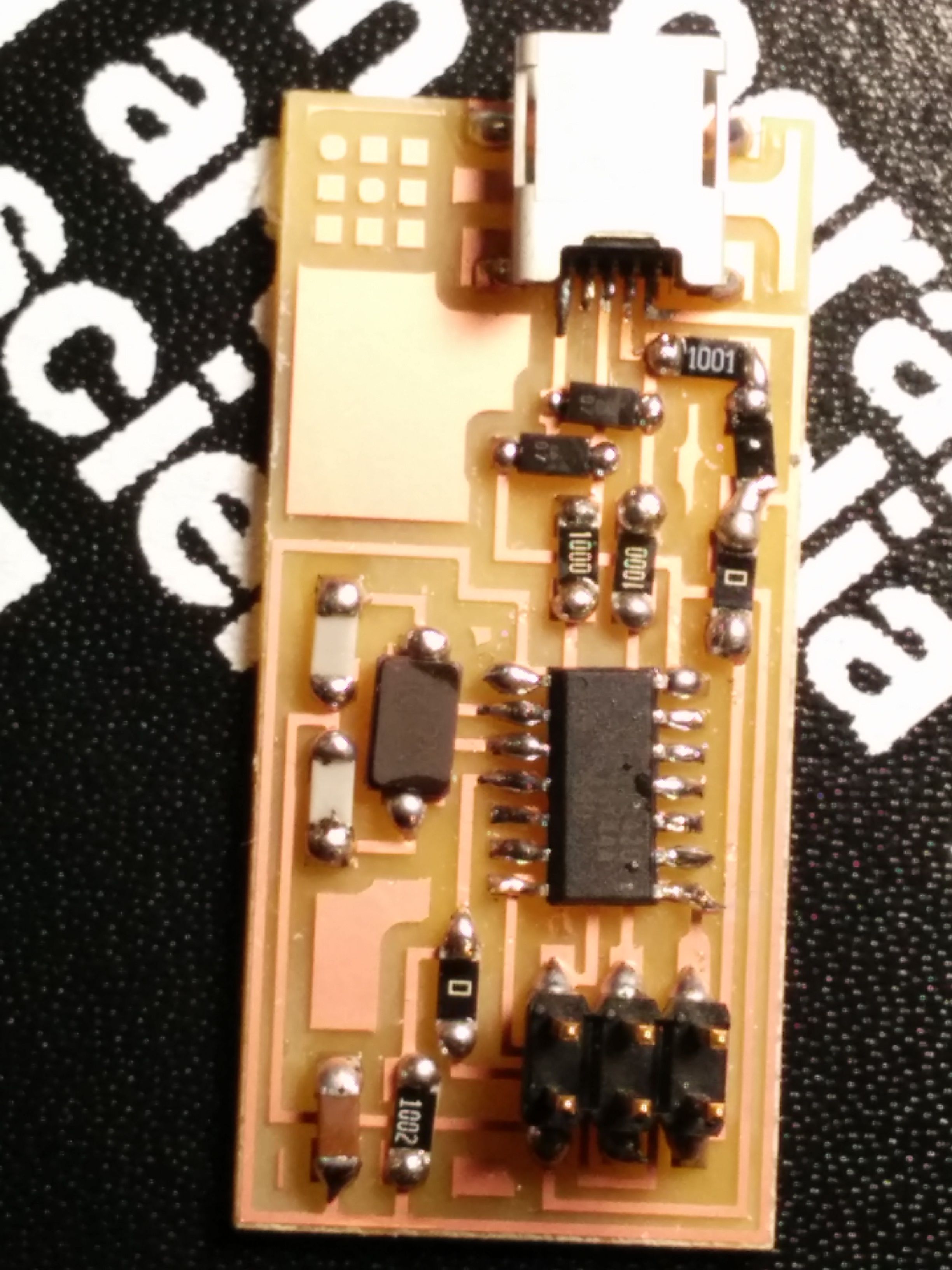
Final Circuit Board
This is the final programmabled programmer (after it has been programmed). I am happy that it worked (on the first try... The Gods of Debugging must be on my side). I think that I can improve on my soldering skills: the solder points are a bigger than they need to be (I sometimes connected two terminals with too much solder).
I still have zero idea how the circuit works, and I have very little understanding of what it is supposed to be used for.
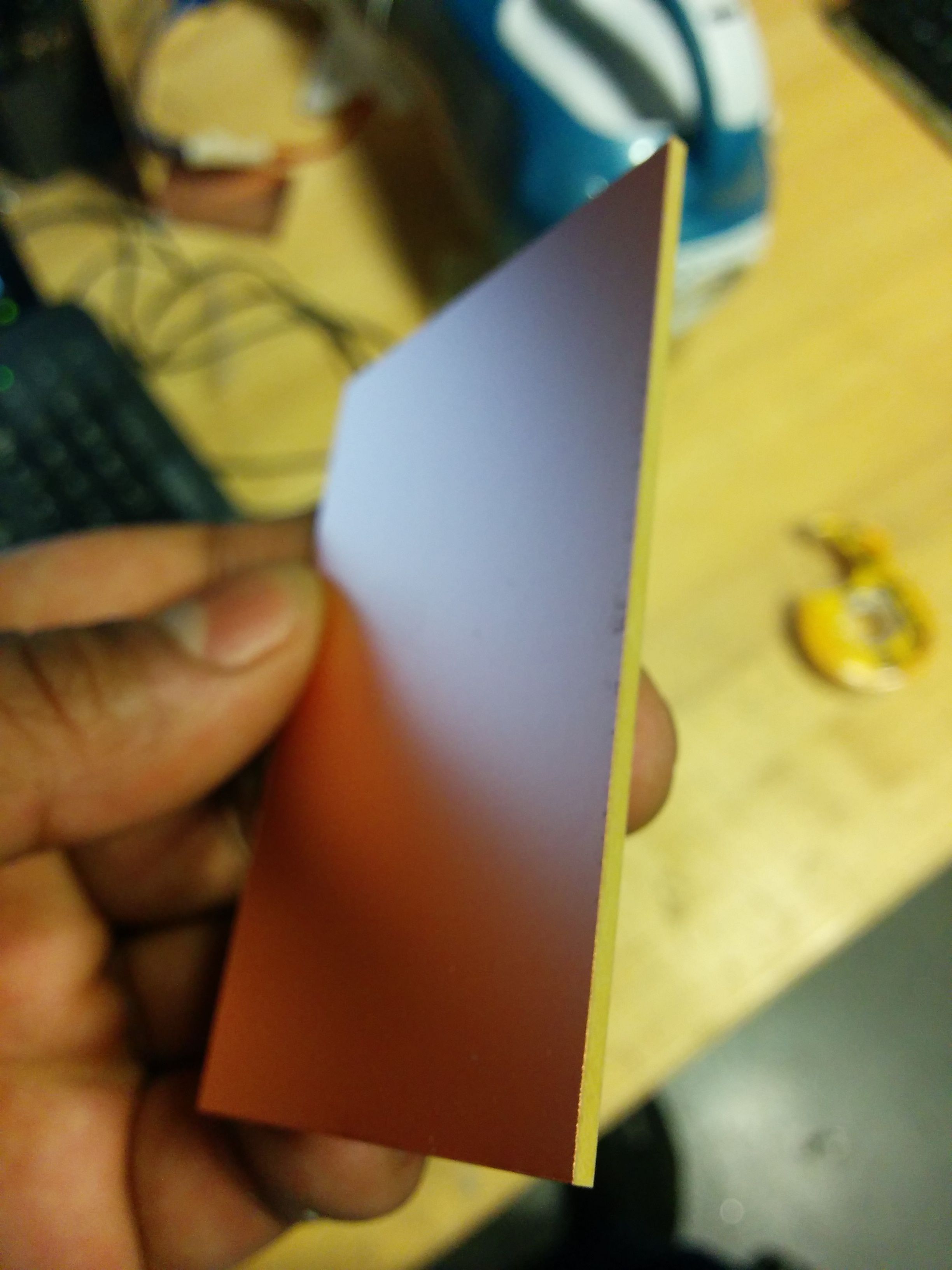
Initial board substrate (copper sheet on top of plastic
This is what I am going to turn into the circuit board by milling off the copper so that the resulting 'traces' are the connecting paths between the components
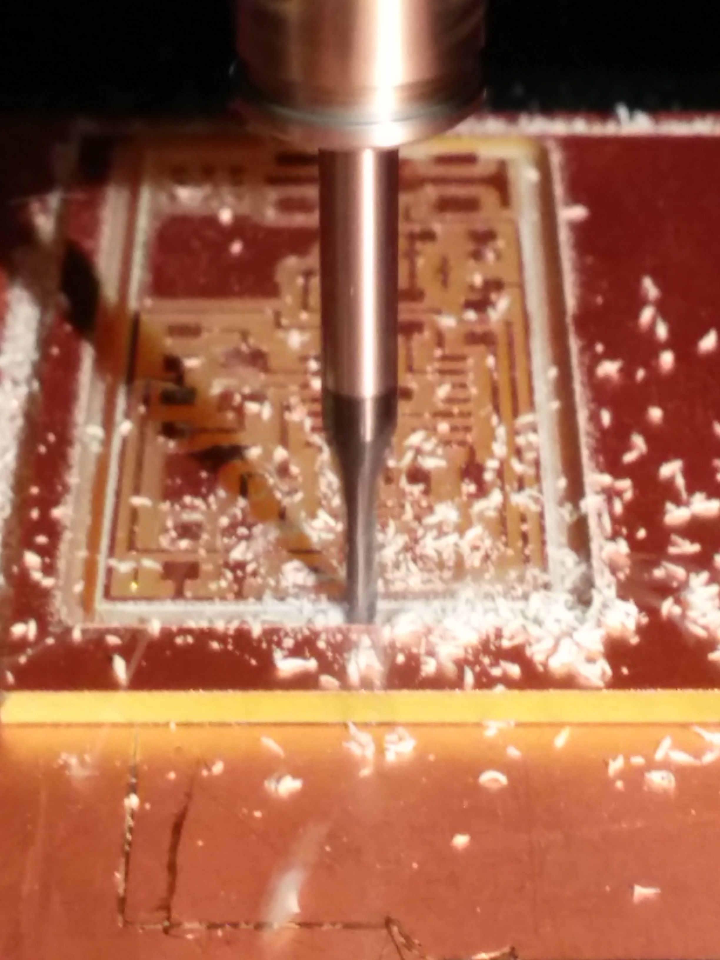
The milling machine at work
This is a picture of the milling machine after it was done creating the traces/paths, and it is now cutting the board out out of the board substrate. The milling head is very small and does multiple passes to clear out the material for the traces, and also multiple passes to remove cut off the board
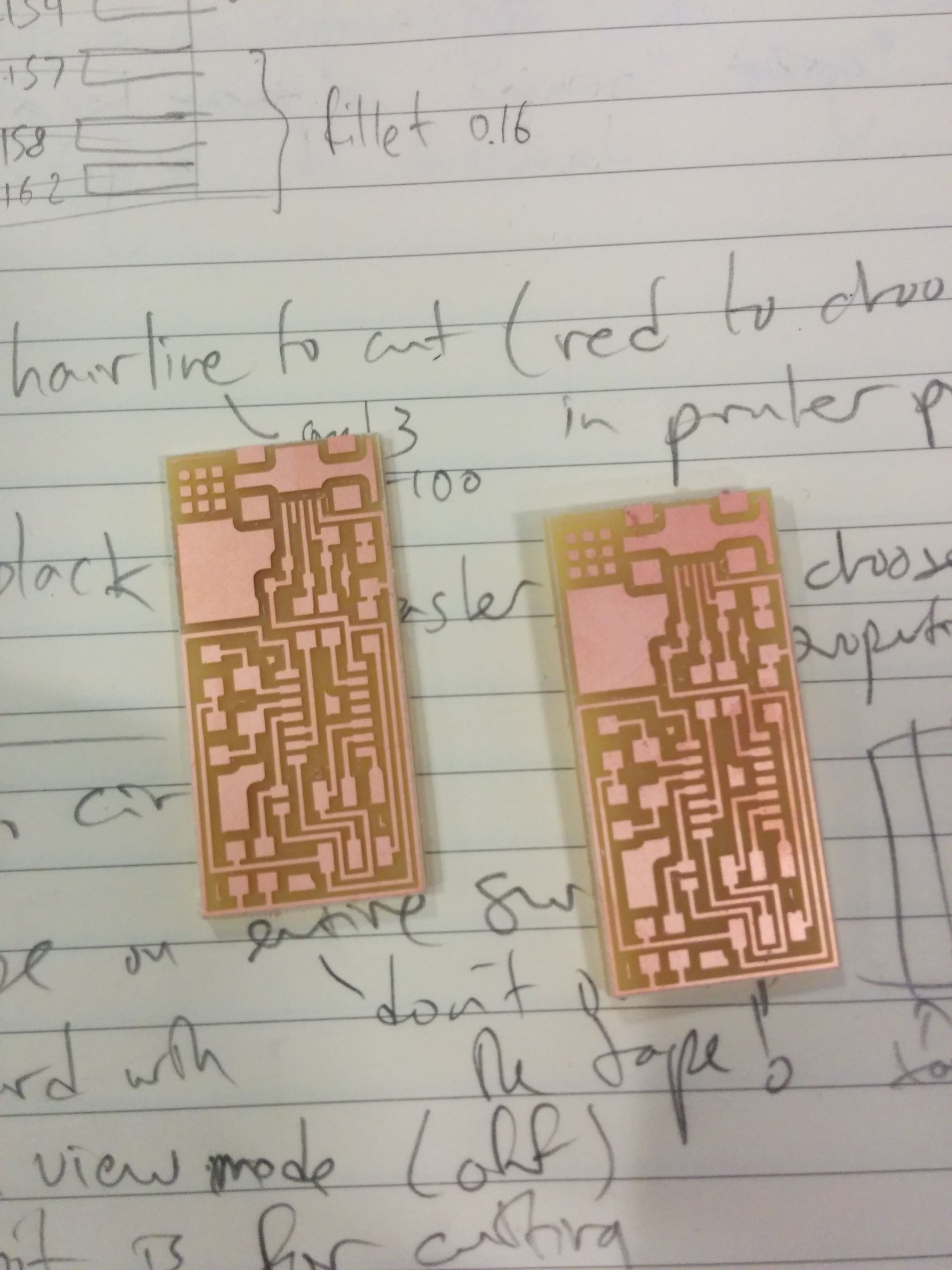
Milled Boards
This is what the milled boards look. I made two because I was predicting that one of them would be wrong and I wanted a backup. I was able to make them from the same block/sheet by moving the origin to the start of the second board
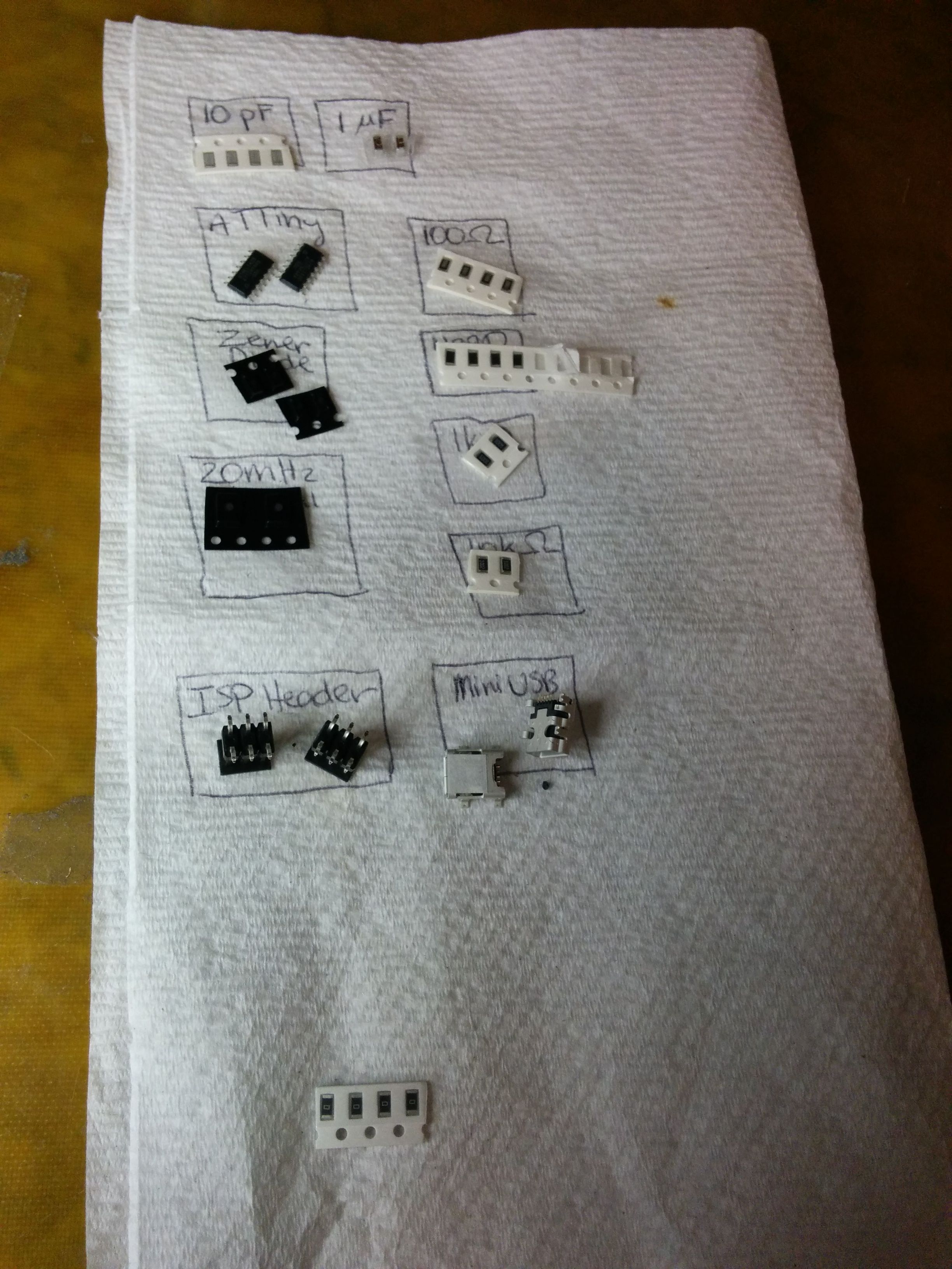
Planning system
This was quite useful and we learned it from fellow classmate Randee (spelling?): each component is labelled in a little box. This prevents us from having to find a component every time we needed one from the dozens of drawers, and it also makes sure we put things back immediately
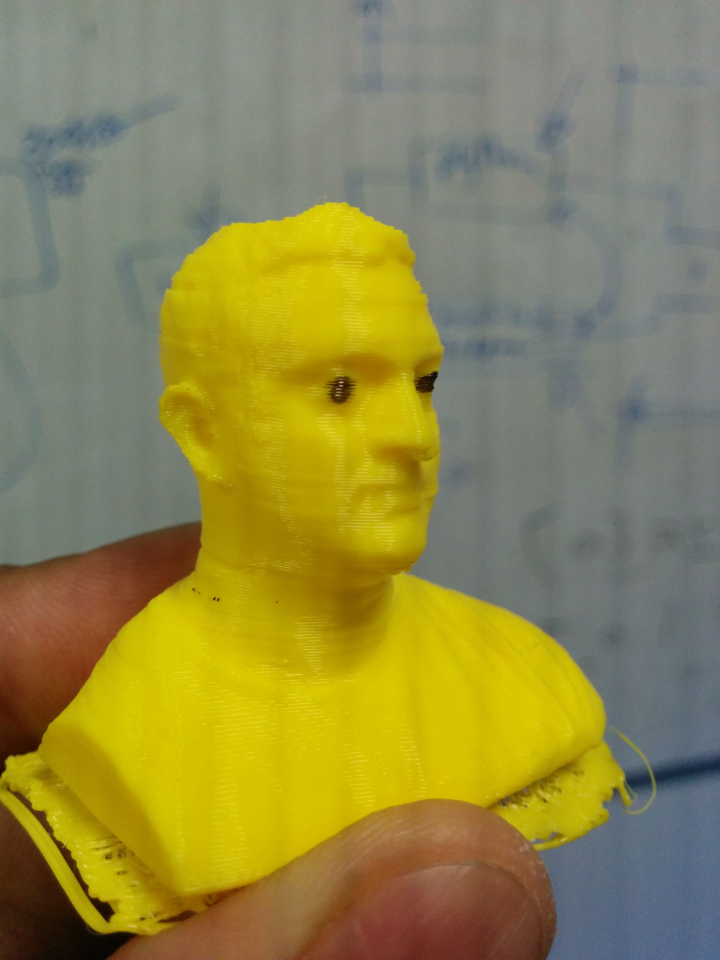
3D print of 3D scan of a person I know very well
The print turned out surprisingly well. It was smooth except for random little bits of fillament that I manually clipped away under the nose and near the ear.
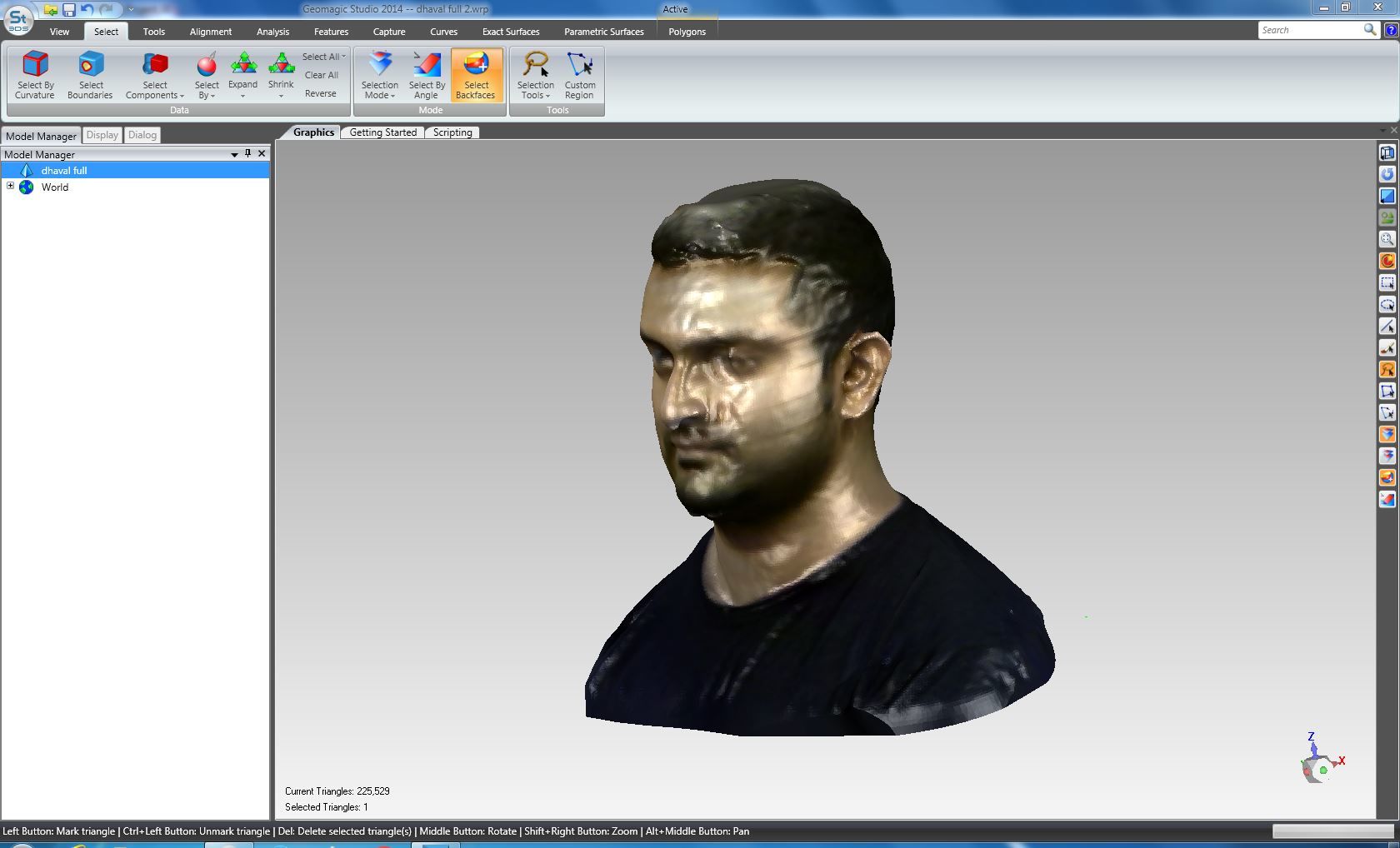
Scanning process
I scanned using the Sense scanner and it took many iterations until we got a decent-enough scan. I sat on a chair while a friend held the 3D scanner and another friend rotated the chair I was sitting. We had to get the speed right so there were no holes. In one of the scan I moved my head slightly back and ended up looking like a modern art sculpture. Then I imported the PLY file into the 3D magic software and smoothed it, removed part of the chair in the back that was scanned and remove spikes/holes.

Busts about to be printed
This is the busts about to be printed after the gCode was generated. There was always this weird filament above the heads.
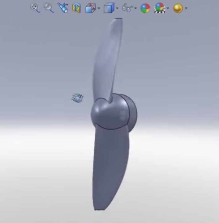
Propeller for drone
I wanted to see how well I could print propellers for my drone. First I had to make said propellers in SolidWorks. I found this great tutorial online that explains how how to loft surfaces, sweep (copy+rotate) sections, etc.
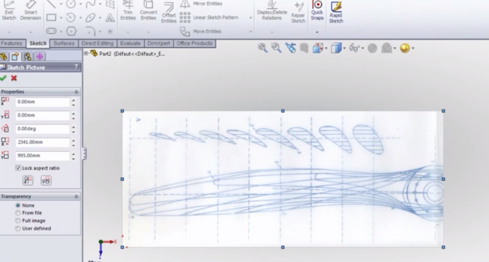
Propeller based on this blueprint
I learned to sketch from blueprint. The tutorial teaches how to copy the sections of the prop and then loft a surface along the long axis of the prop
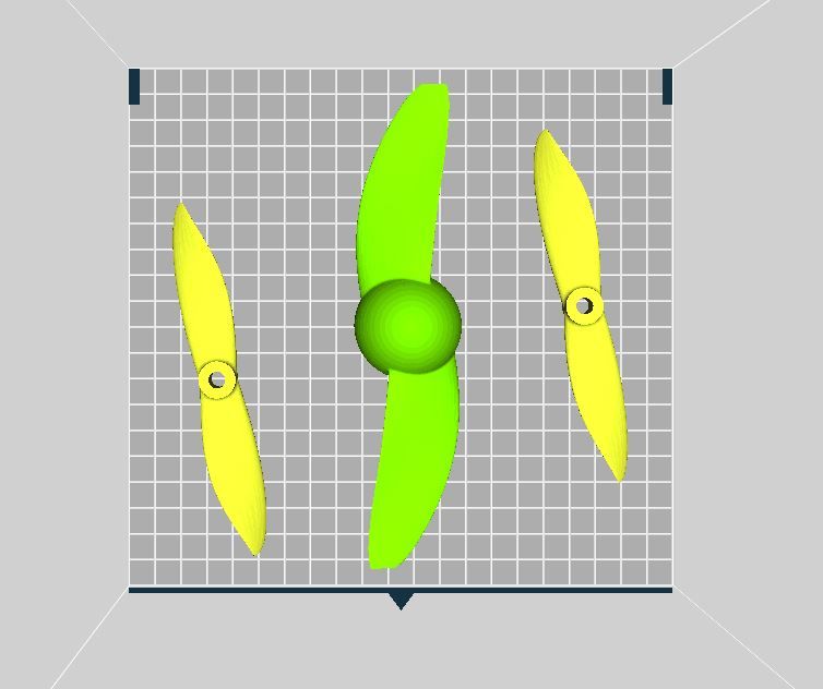
Prop ready to print
These are the props ready to be printed on the 3dWox. Some of the props are from online .STL files I found.
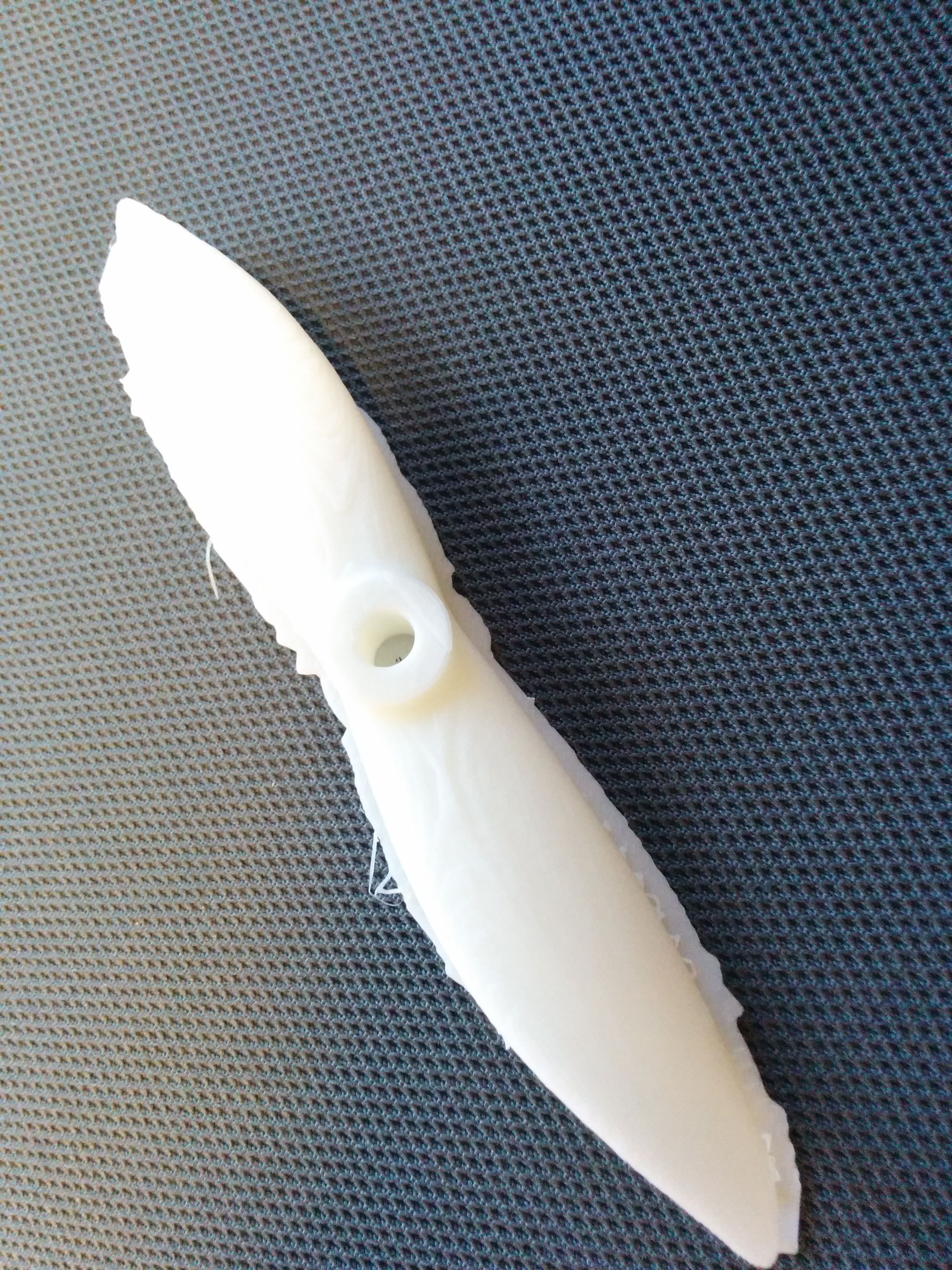
Printed prop: smooth and correct curvature
The prints looked good in the the surface were quite smooth and the curvature looked good.
Hard to detach from mount
Because the propeller blade is so smooth, it was hard to detach them from the mount without breaking the blade. I printed the same propeller on the Eden printer and it looks much better in terms of now having such a big problem with the mounts
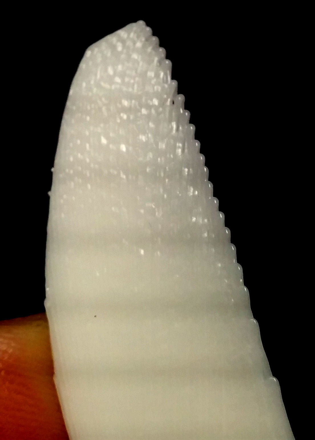
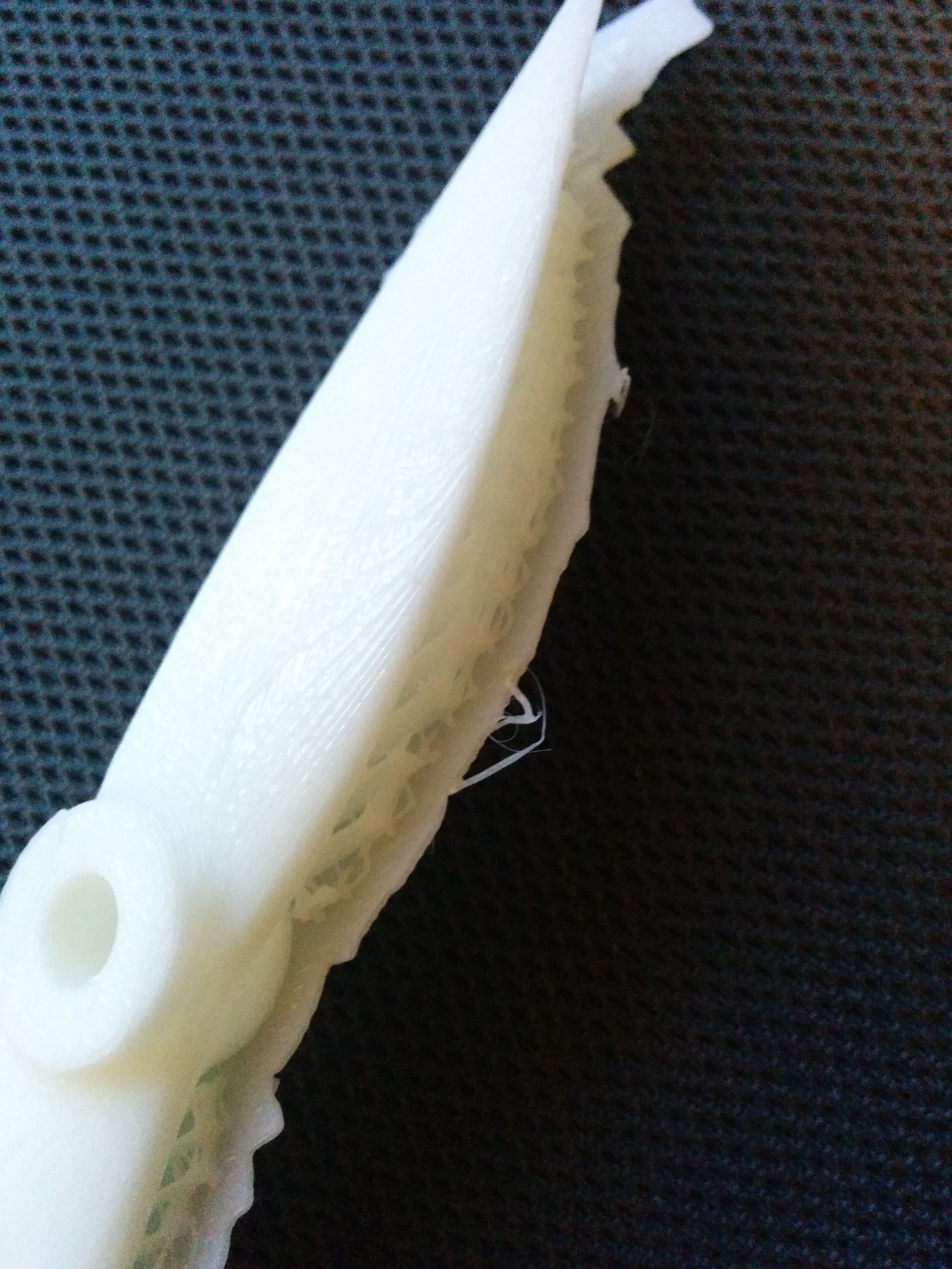
Edge problems
As Neil said, 1 filament-wide prints can not do too well. The part of the blade that is the finnest looks frayed - you can see the filament layers. Perhaps that is ok for a propeller, otherwise I will have to make sure the thinnest parts of the blade are at least 2 filament-widths wide.
Floundering in too much wilderness
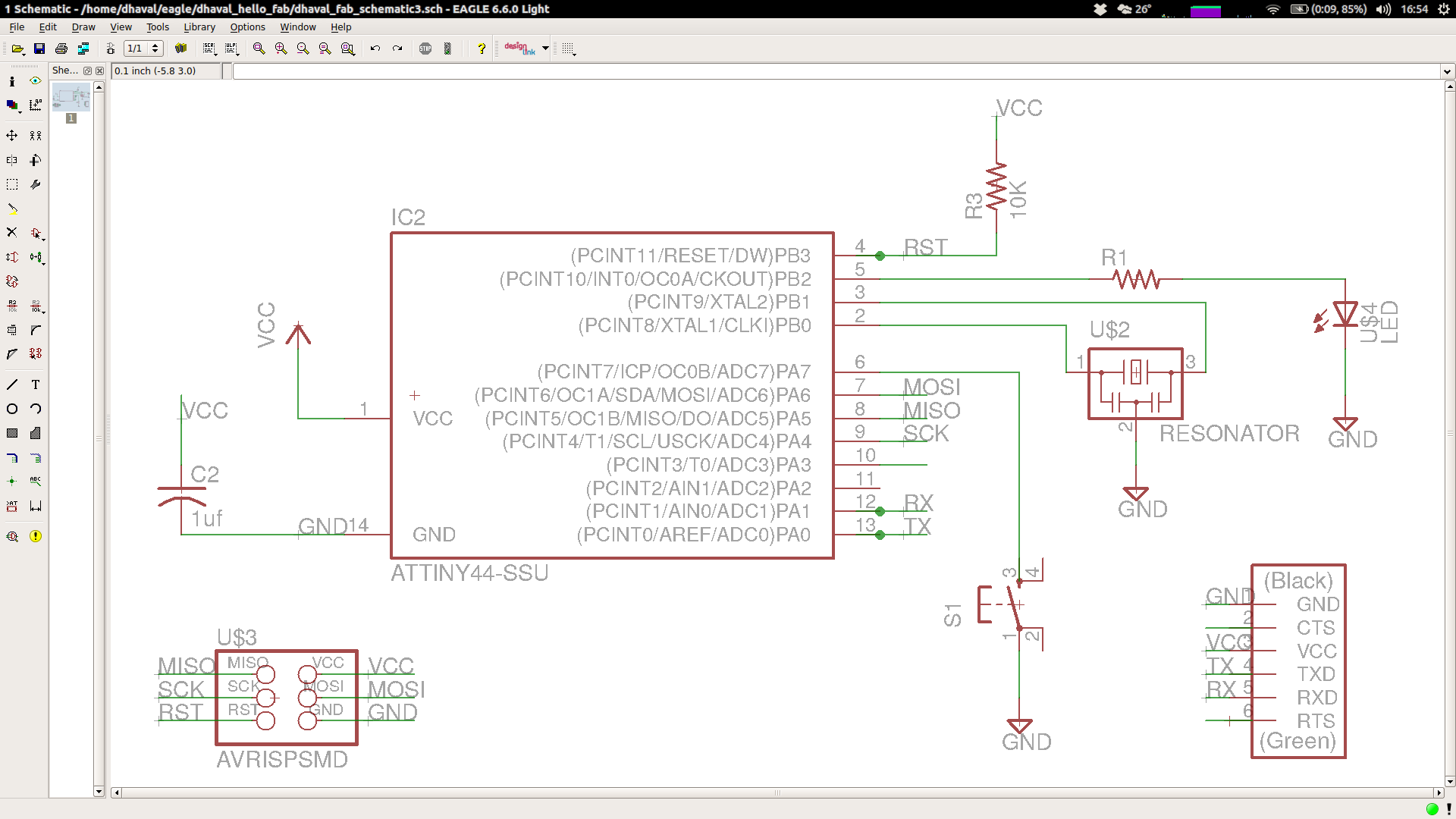
This week's assignment was very frustrating but for none of the reasons Neil said. Eagle had a learning curve, but what was most frustrating is not knowing exactly what components to use. I think that having a bill of materials would help make things a little easier. Some things like the header, etc were mislabelled. When learning from zero, it's hard to know how much of it is me not understanding something critical vs instructions being unclear. I finally found this great tutorial from a previous year that was quite helpful. I was finally able to get things in the Eagle schematic, and I have to say that Eagle is pretty nice, except for zooming/panning annoyances.
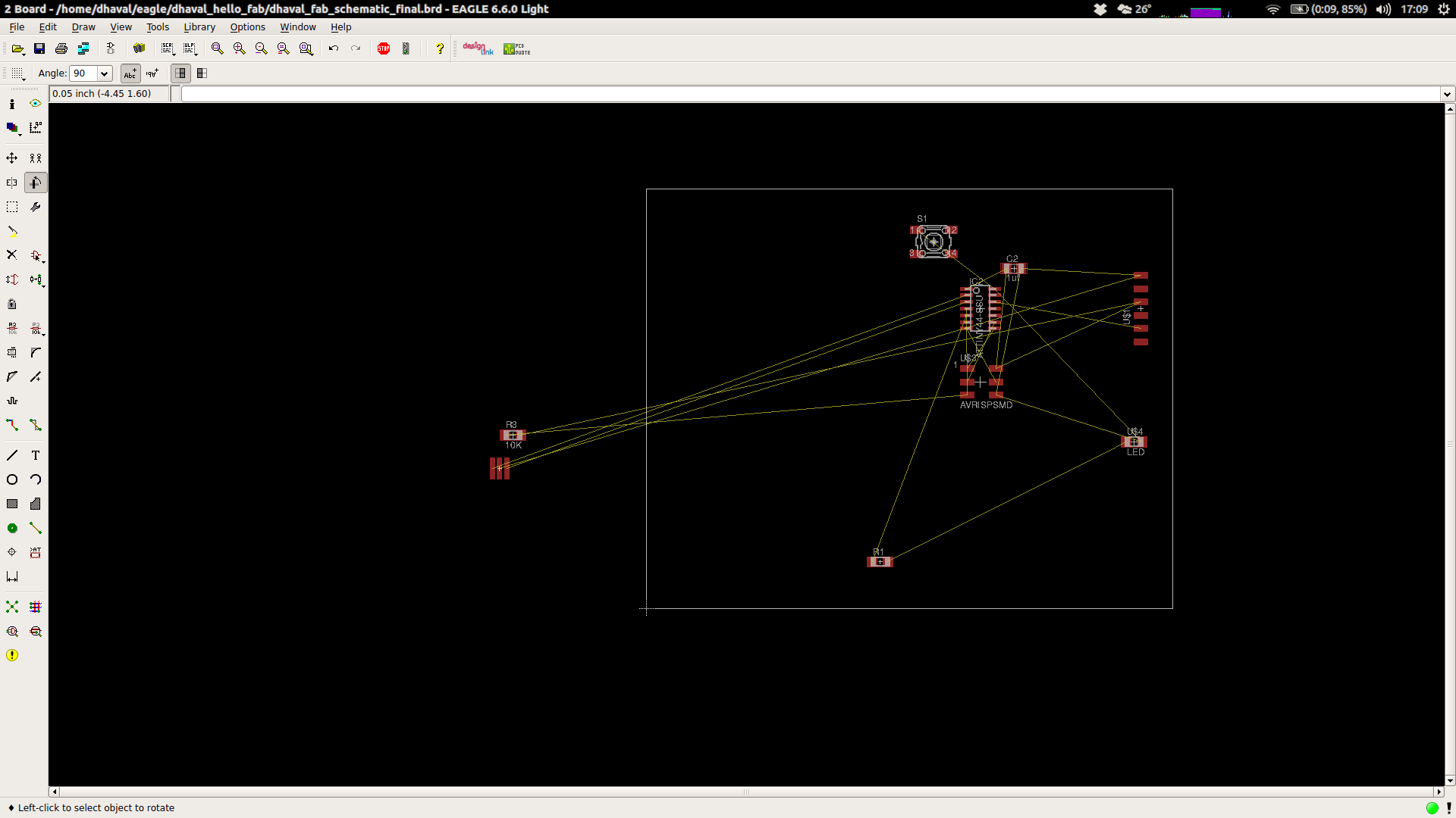
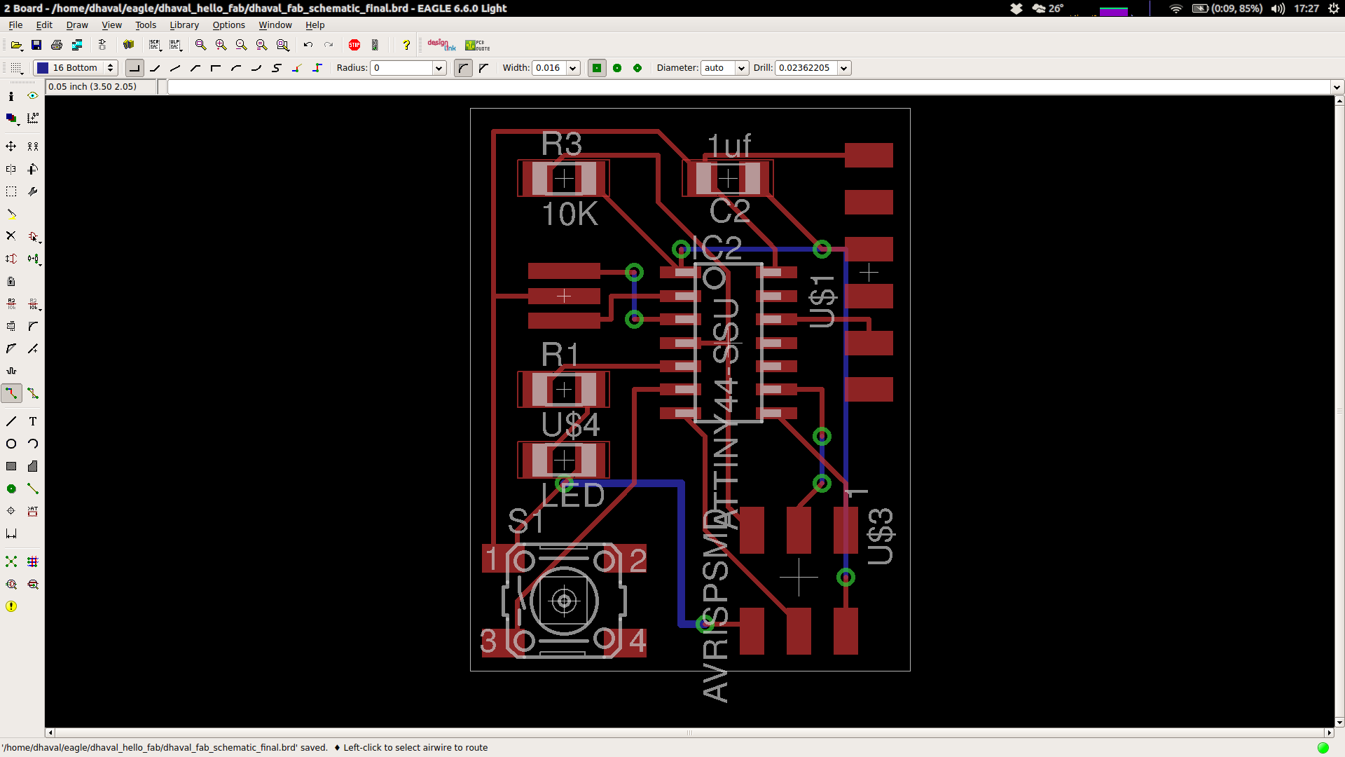
Routing madness
I spent countless hours staring at my screen trying to understand what I was doing wrong because I could not route the traces. First I thought that perhaps I was missing something. I watched countless tutorials on it and finally Ali the amazing TA told me that my schematic is good and that this is just a puzzle to wrestle with.
By the way, is routing a travelling salesman-type NP-hard problem?
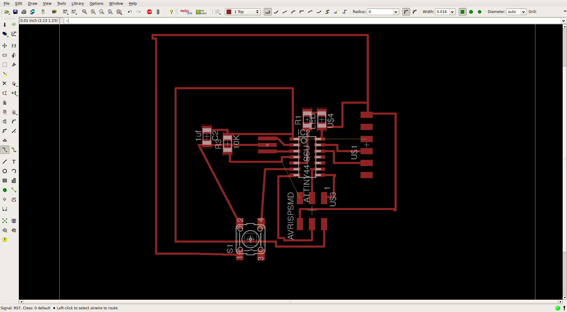
More routing madness..
Still no success :( but Ali gave a good advice: 1. start with the physical distance (e.g. resonator needs to be close to chip) 2. find connection one at a time that are blocked by traces and fix them first and ignore the air wires 3. Iterate, and if need be, break some connections and start over at worst 4. Keep the most complex components for last
Still no success
This (as ugly as it looks) could be made to work with 0-ohm resistors, but there is a better way :(
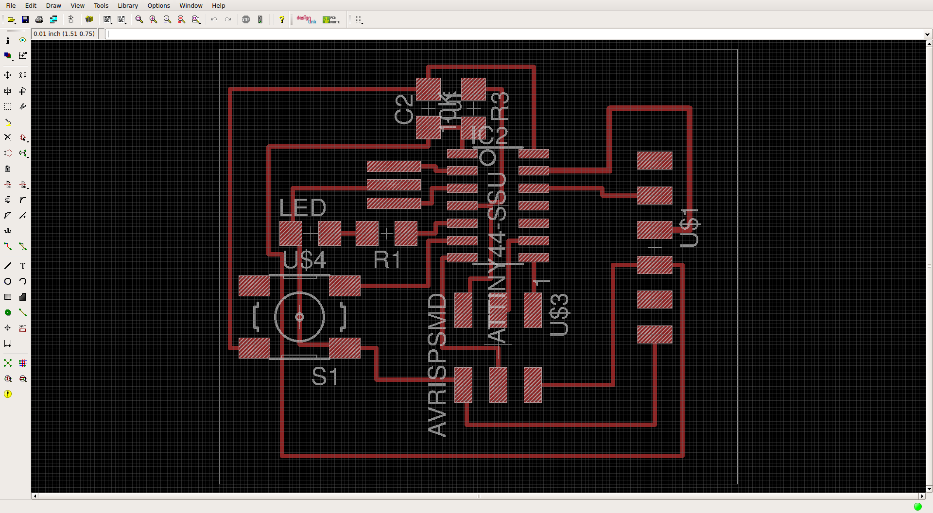
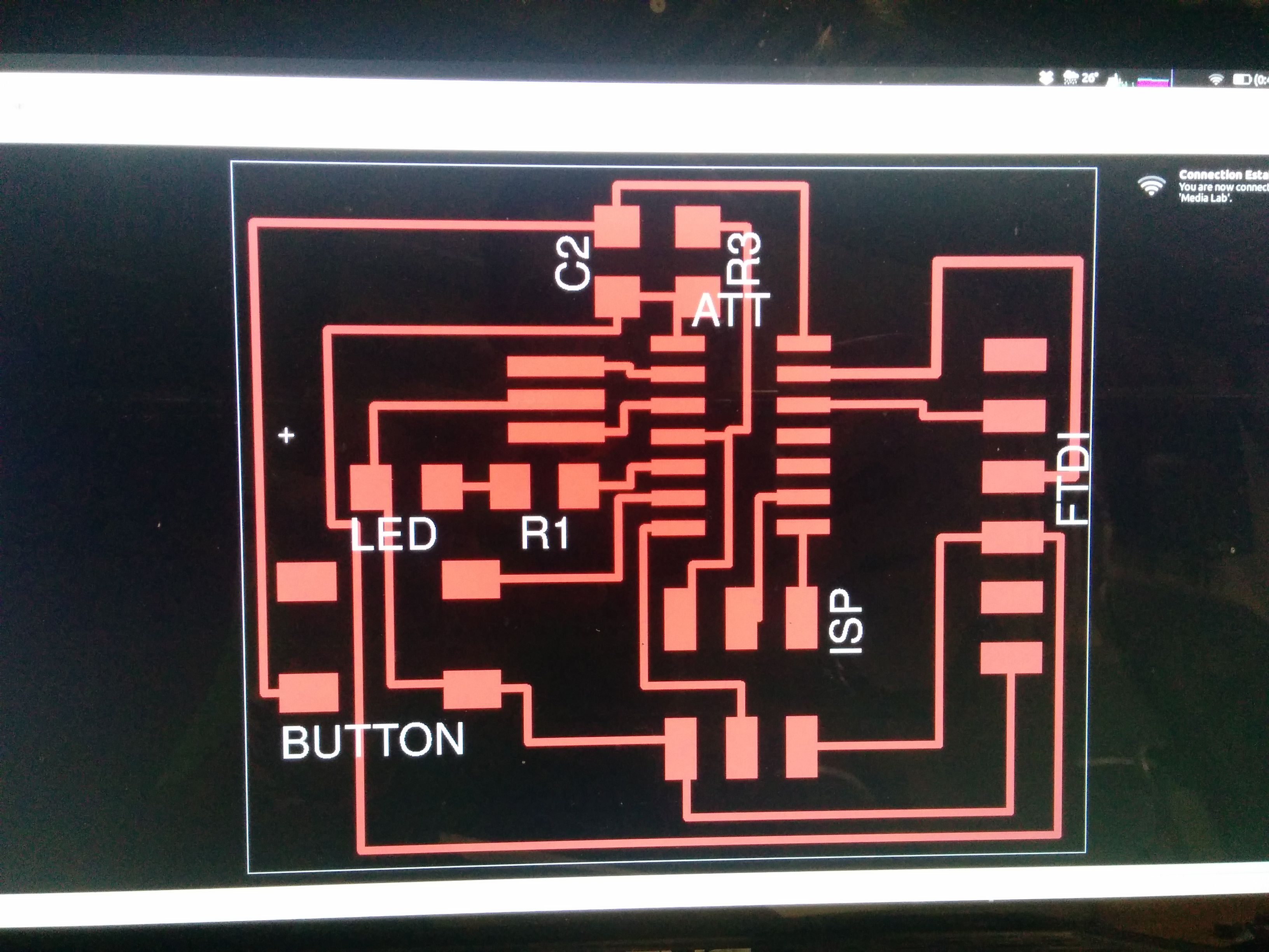
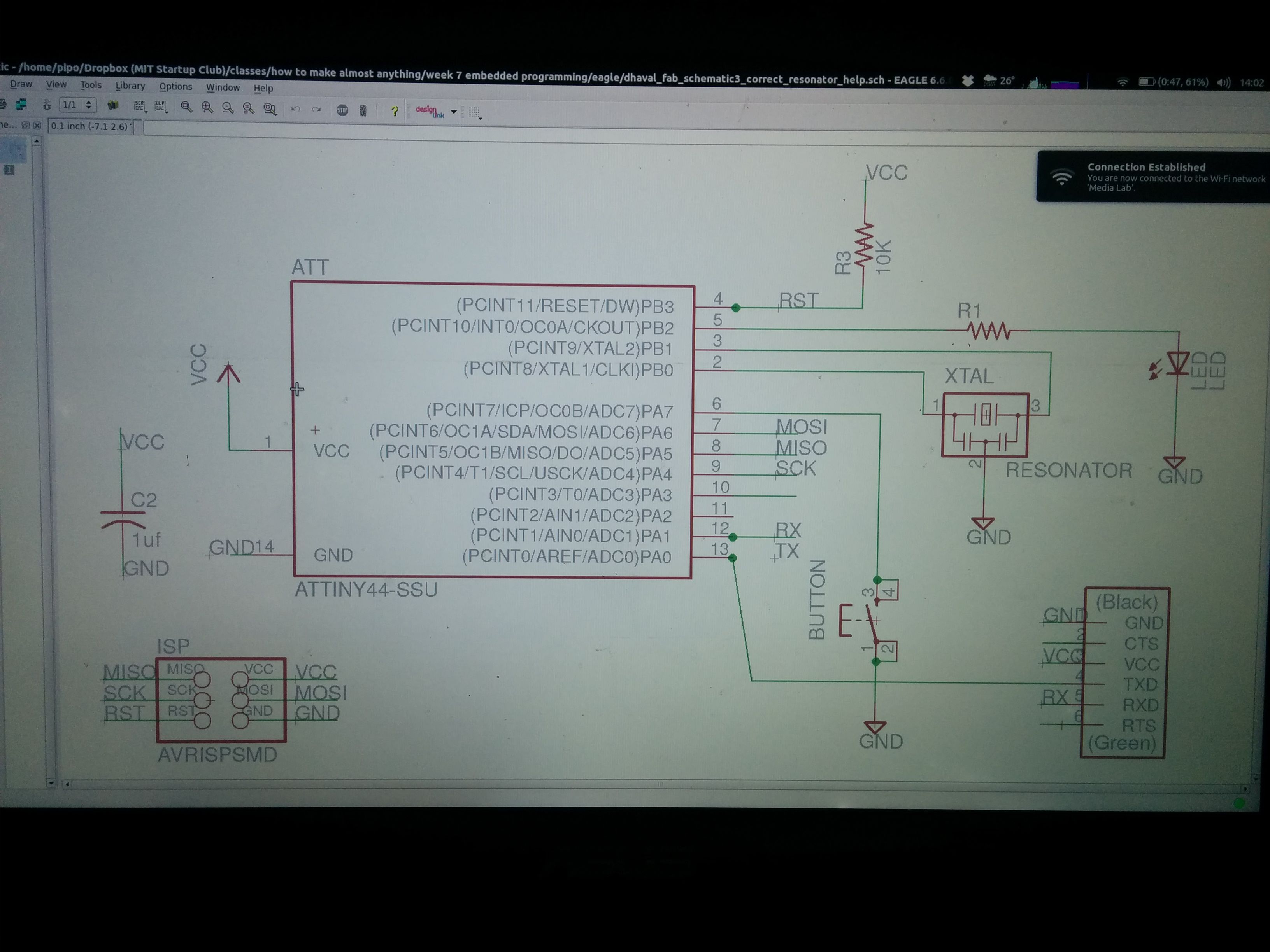
Final result from Ali
Ali helped me last night to finally route my traces right. This is his attempt. I still have to export the PC to PNG, mill and solder..
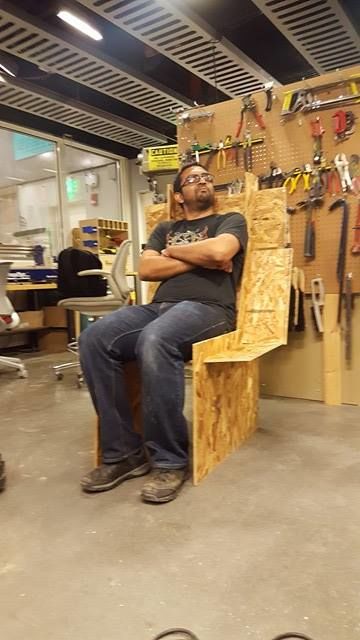
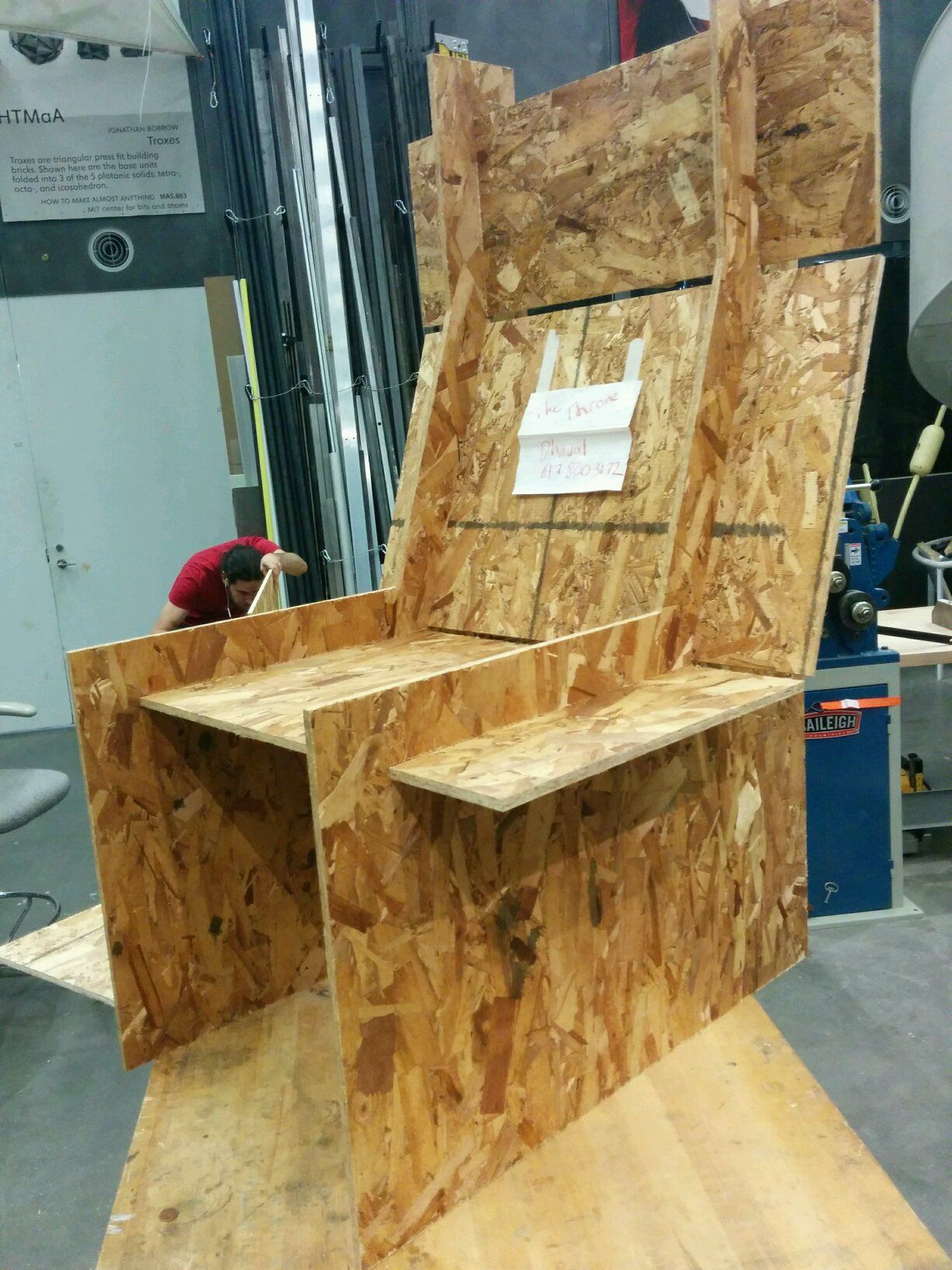
This is the final chair
I wanted to make a comfortable high-back chair prototype and I wanted to see how easy it would be to make it 'press-fit' style. I am surprisingly happy with the result. Although it doens't look very pretty because I was not concerned with esthetics, it fits very well and holds my weight! You can download all the files here!
Improvements!
In terms of being strong enough, I think that using thicker and stronger wood would help! Right now the seat and back boards just slide in but I bet there is a better slotting/joint system I could use for this. Otherwise I can just buy a bunch of supporting metal elbows and screw them in! Otherwise, I want to fillet the corners, maybe do some kerfing and have the side be one piece, and add some pretty engraving on the side. I also wonder how hard it is to do some Finite Element Analysis to see how to reinforce the chair.
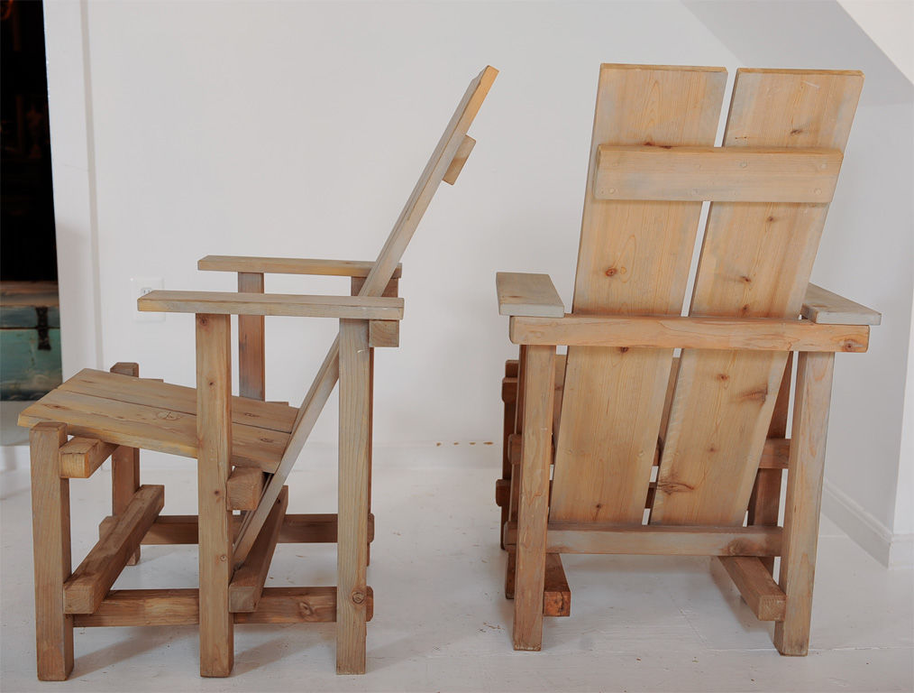
This style of chair was my inspiration
But I wanted to make it with as few separate pieces as needed.

Solidworks
I designed the chair in solidworks. It took a while to learn *how* to think about making it. There you can see what it looks like in Solidworks
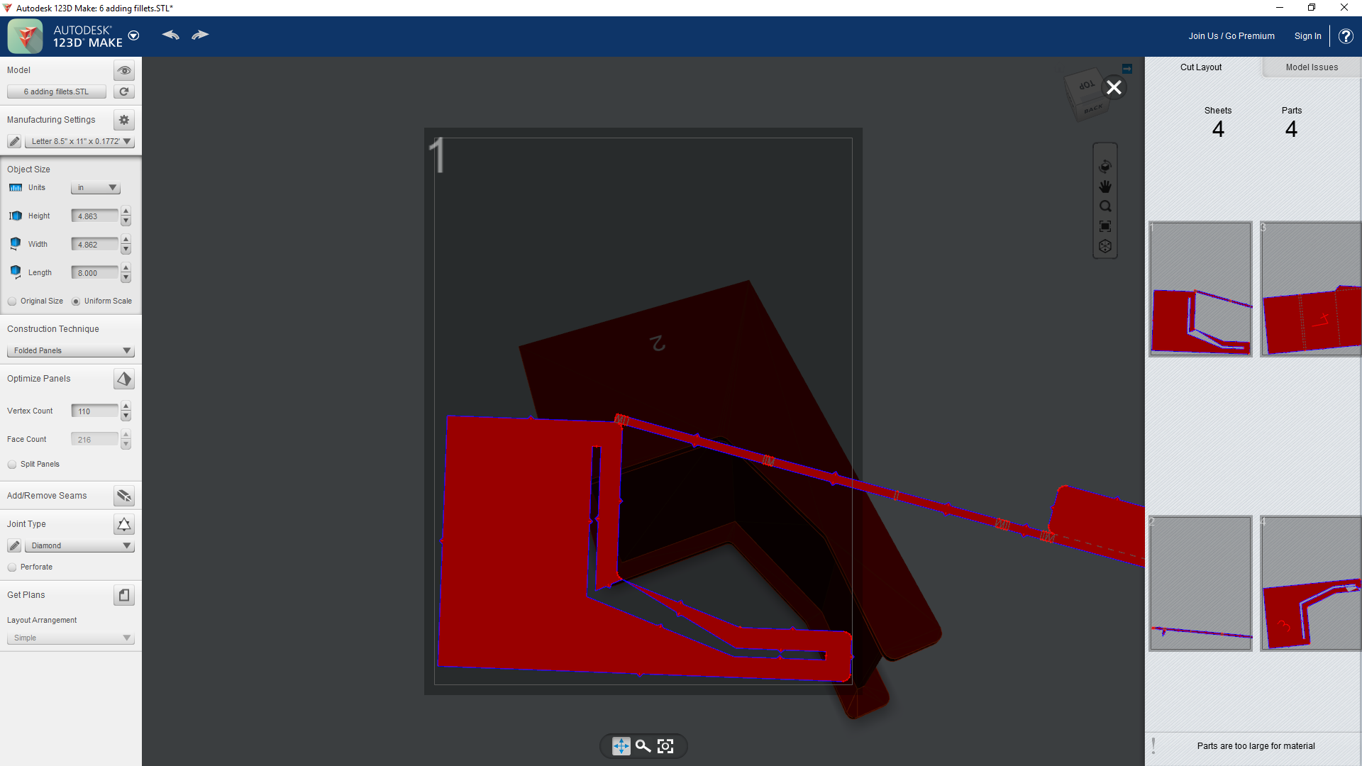
123D Make Fail!!!
I will not try to use 123D Make again! It could not import the STL from Solidworks. Here you can see what 123D thinks the side panel looks like. Maybe if I was Salvador Dali, I would be ok with it..
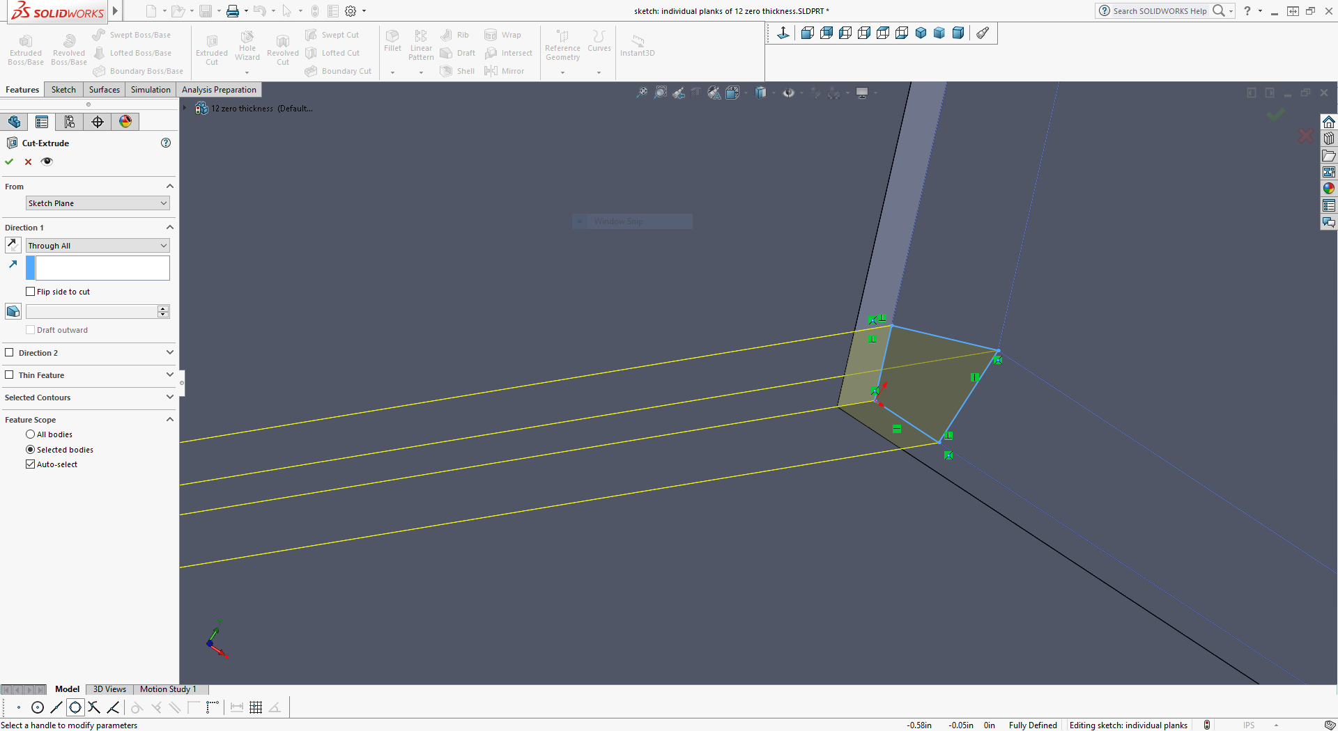
Zero Thickness Error
Because I don't want to use 123D anymore, I tried to make the fittings in solidworks using extrude-cuts. I didn't get to making it in the end, parly because of this weird "zero thickness error" that happens when parts of a part touche at a point or line without thickness

Hack Solution to Zero Thickness Error
Solving the "zero thickness error" involves leaving a slight (< 0.001 in) lip so parts still have some theoretical thickness. But doing this for each slot is hard. Maybe there is an automated way to do this in solidworks, but I could not figure it out..
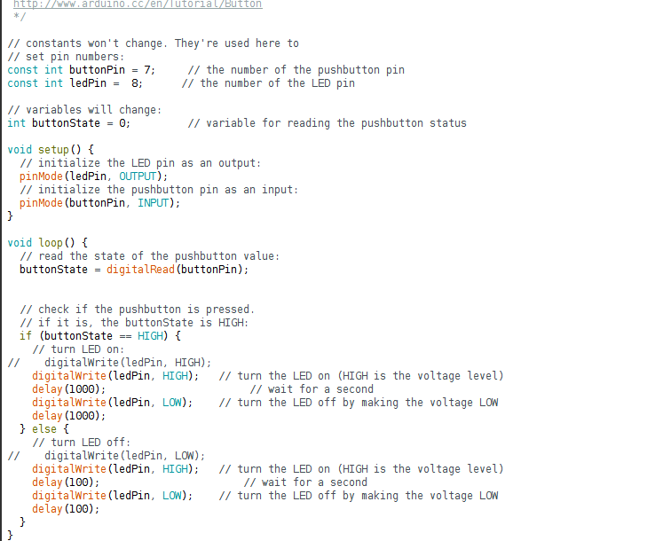
Final Code that does the button and blink
This week was challenging: integrating all the different layers of abstraction and getting the final result took a lot of debug time. Big thanks to our TA Amanda for her immense help. The echo also worked well!
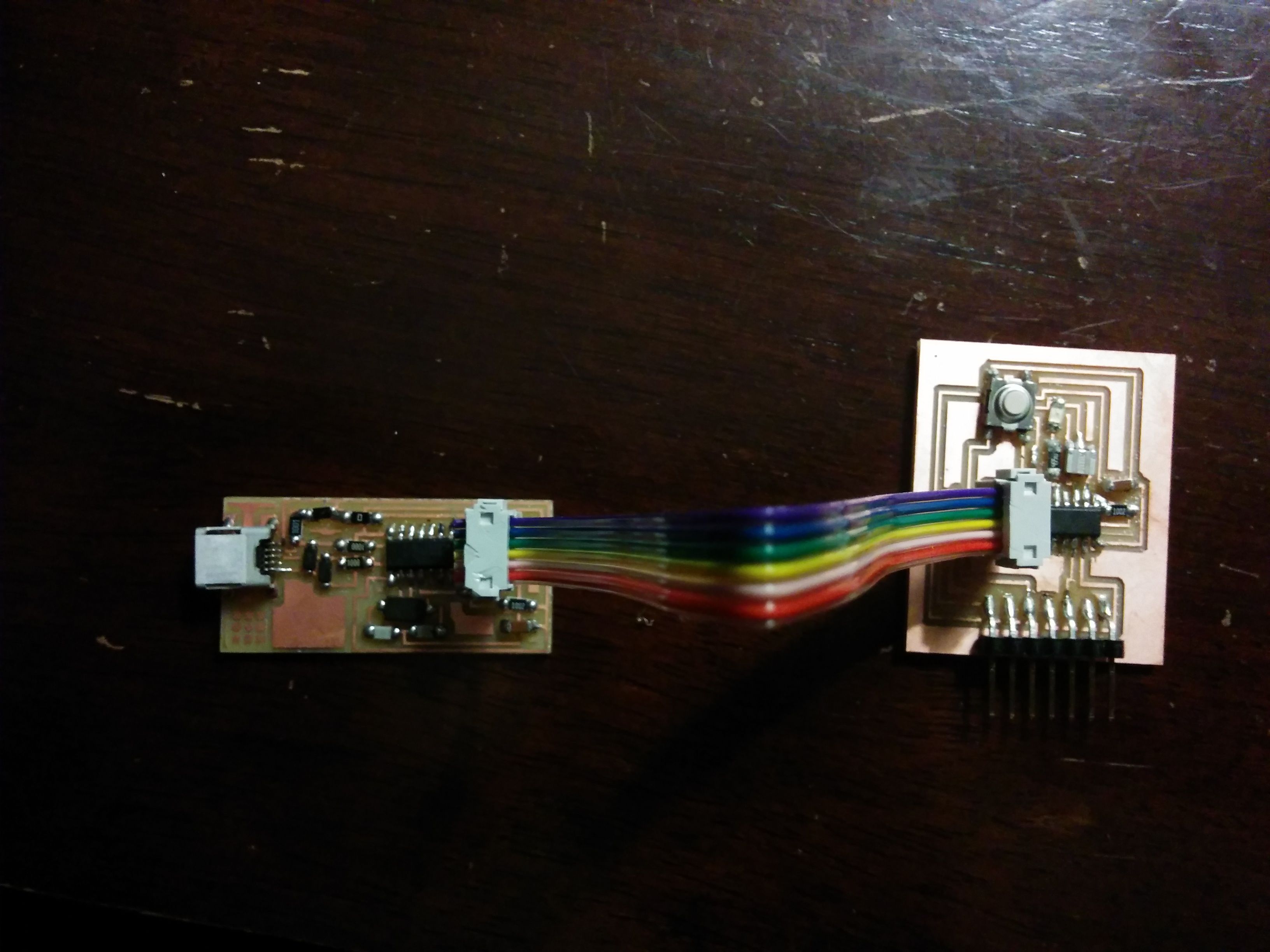
Final ISP and Board
I had not finished my board from the electronic design week (because I was not able to do routing in time) and so had to build it this week. One of my big insights learned was that sometimes the solder could be enveloping the microprocessor leg but not conducting with it. Because you cannot test the leg and trace continuity, there is not way to debug. THe solution is to reflow the solder on the chip till it conducts well. This fixed the problem.
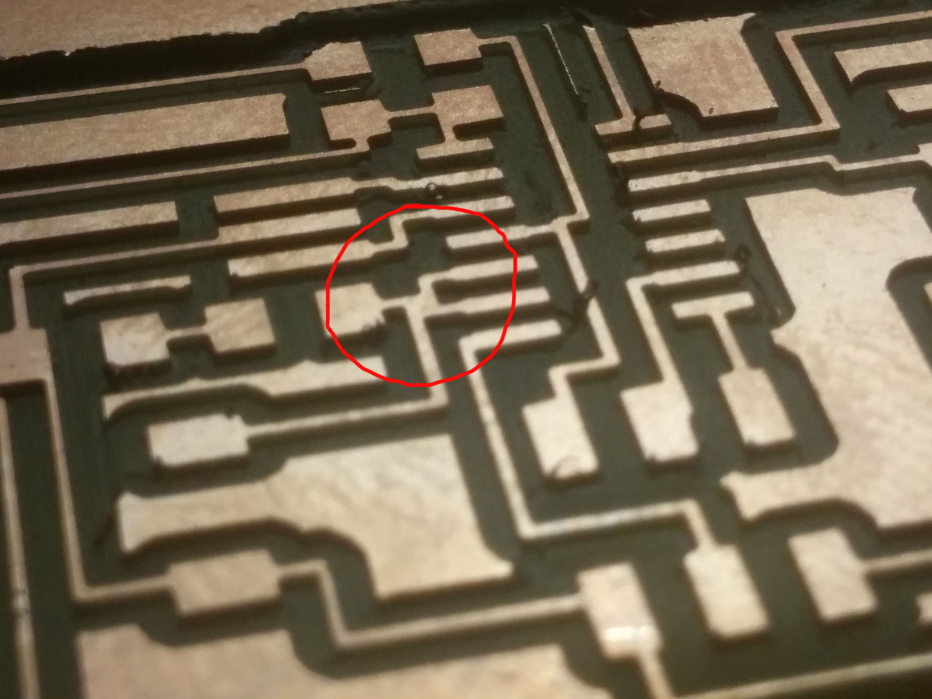
Problem: Traces too close
One of the problems we found was that the two traces on my board (circled in red) were not supposed to touch but did. It took a while to find this bug but eventually the solution was to use a knife and cut the trace until they were not conducting.
Above traces not supposed to touch
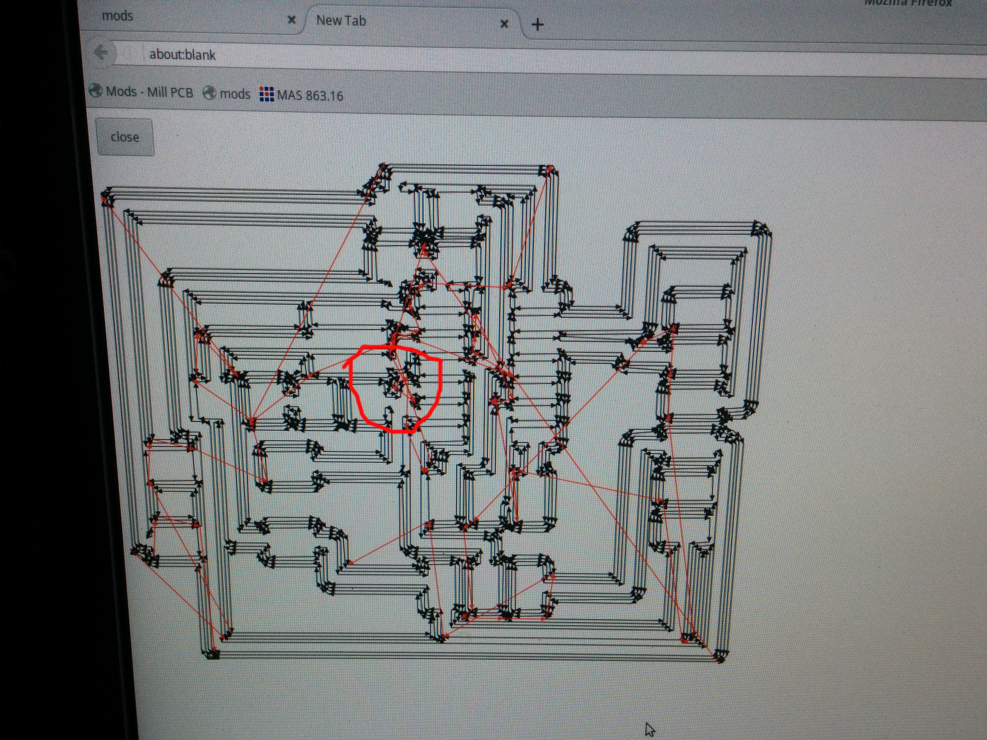
Path passes too close?
This circled region is where the paths were too close and the paths ended up not separate. I guess the solution is not to route traces too close to each other in Eagle? Or is there a way to increase the resolution on the board to prevent such an issue?
Wired button wrong
I should have wired the button such that it's default voltage was high, but turns to low when I press it. I simulated the button press to check if my code was working by using a piece of electric wire to force the microprocessor pin to change to high and see if it blinks faster as per my code. It works. Aka the full stack connects
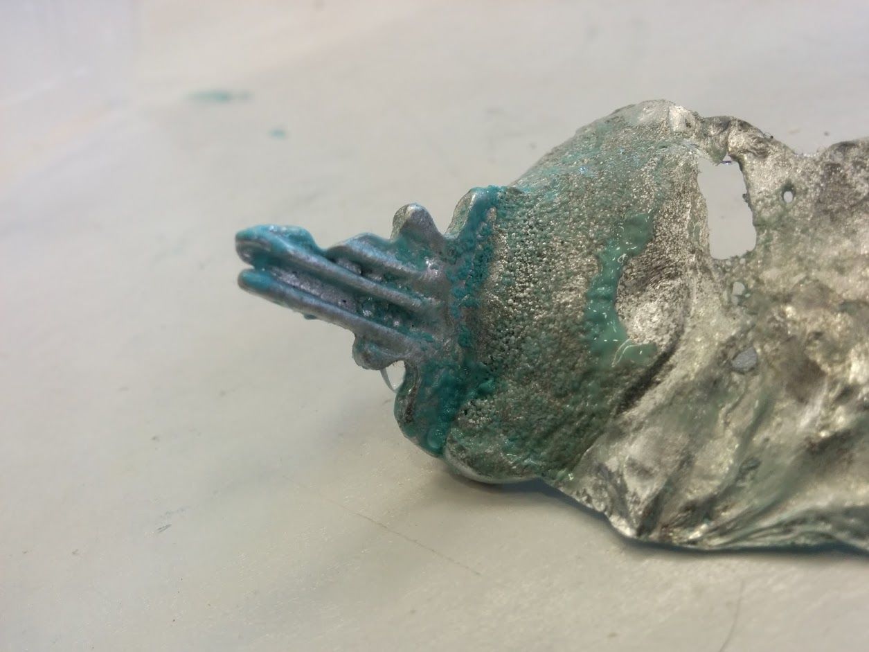
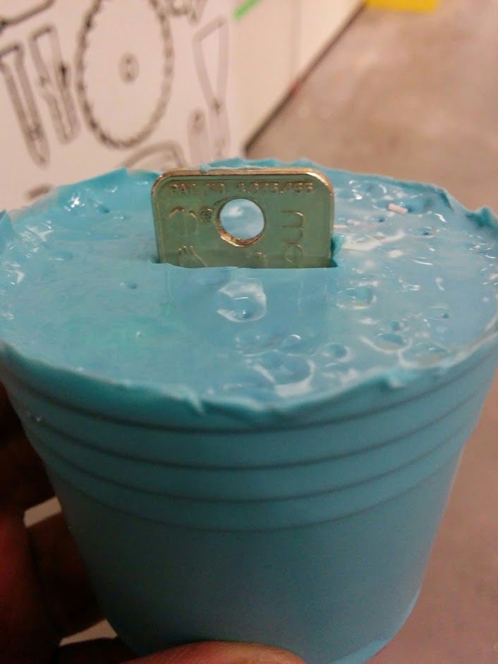
Key Fail 1
This week I decided to try to mold+cast two things: a key and a lizard. This is the key cast out of Centero (check spelling) metal. Unfortunately as you can see the whole lenth of the key was not cast probably because of the verticality of the mold - when metal is poured, it traps air underneath and prevents it from flowing fully in. I have to have a drain hole and air vents.
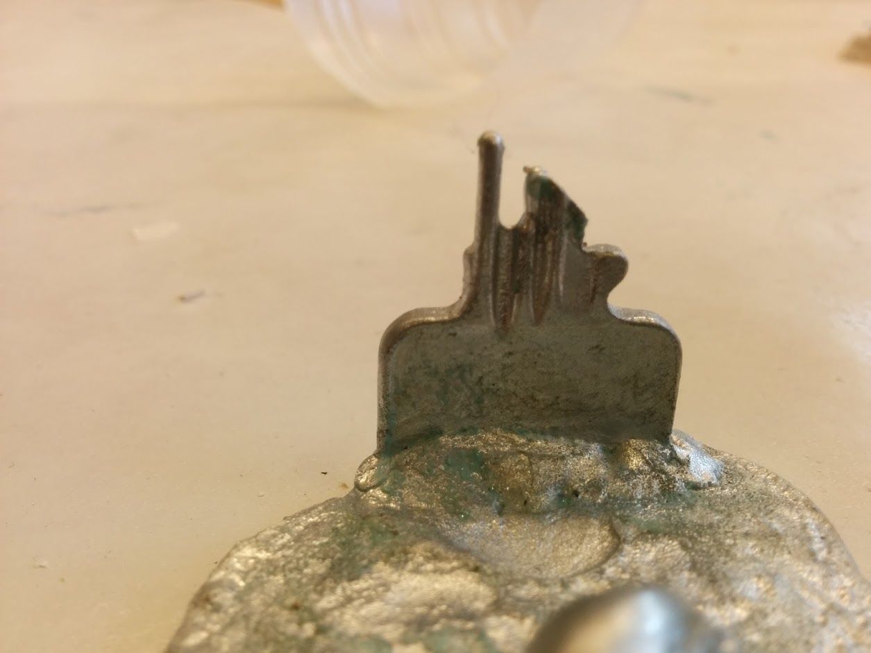
Key Fail 2
I tried again after making a funnel shaped cast intake to drive more melted metal in vain.
Mold for key
Mold being made for key by dipping the key in the Oomoooooo
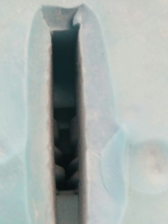
Inside the key mold
You can see that they grooves and teeth of the key were well reproduced
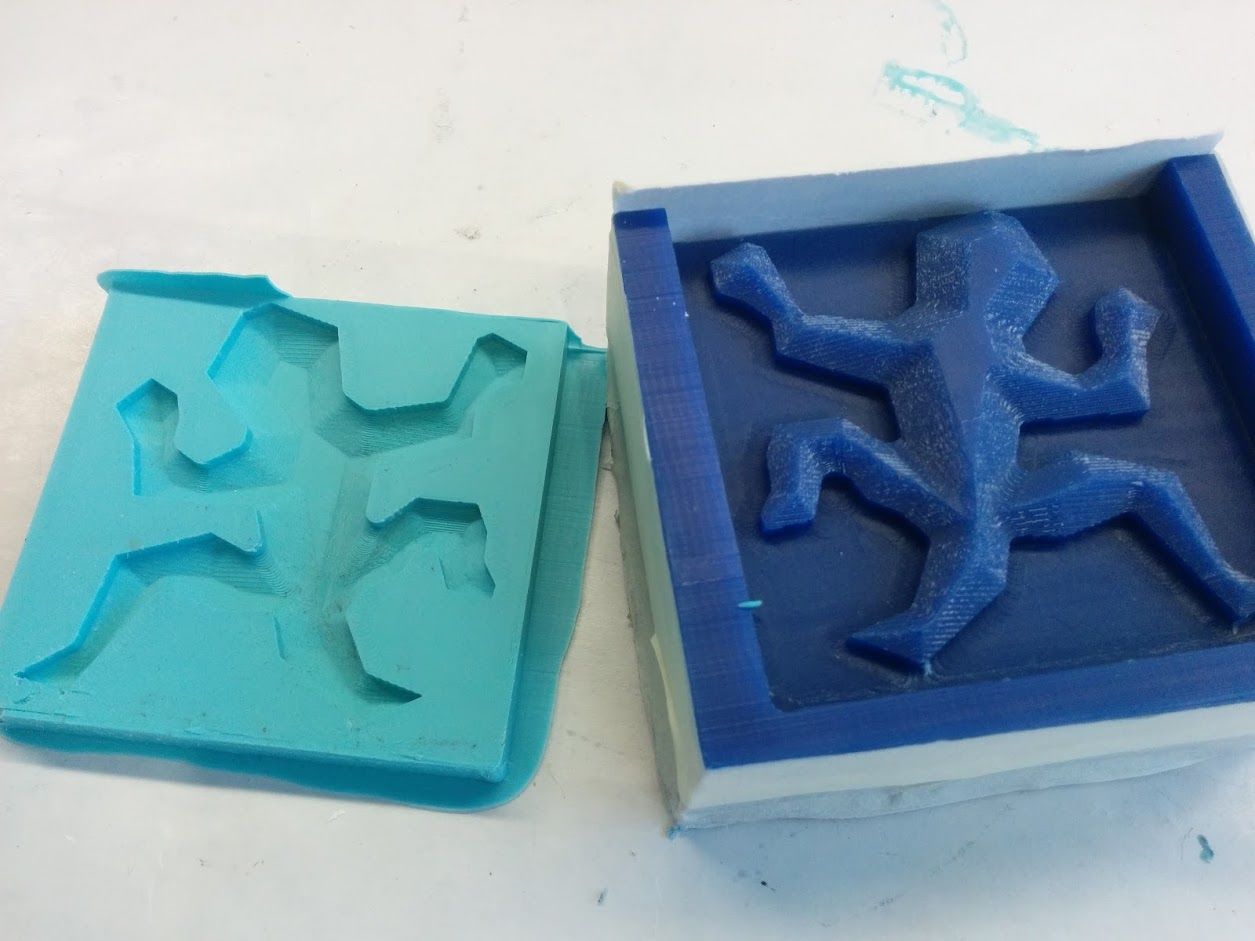
Escher Lizard
This worked out very well. The lizard is an Escher lizard so that if I make many, the can be put together like a puzzle and tesselate a flat surface. The positve mold is made from wax (darker blue) and the negative mold is made of oooomooooooo. The final positive is set as I type made of resin.
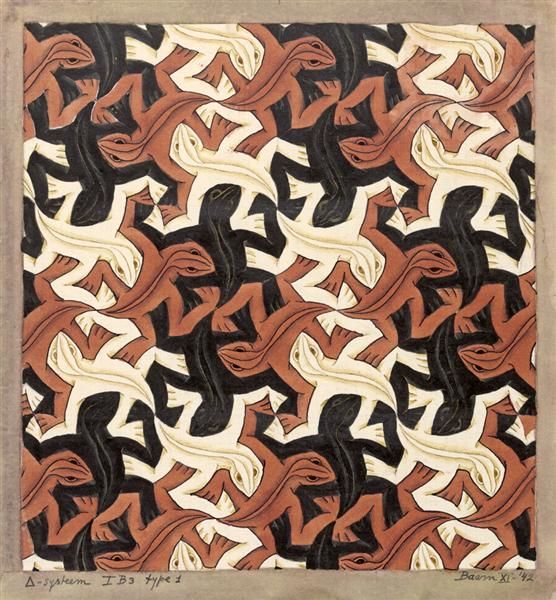
Lizard Tesselation
This is what all the lizards would look like together
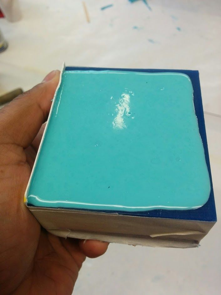
Oomoo on wax Cured
This is what the oomoo looks like when cured (solidified) after 4 hours
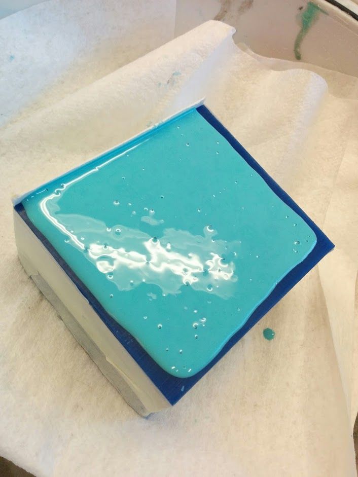
Oomoo just poured
I put the mold in the vacuum chamber to remove bubbles. You can see them at the top
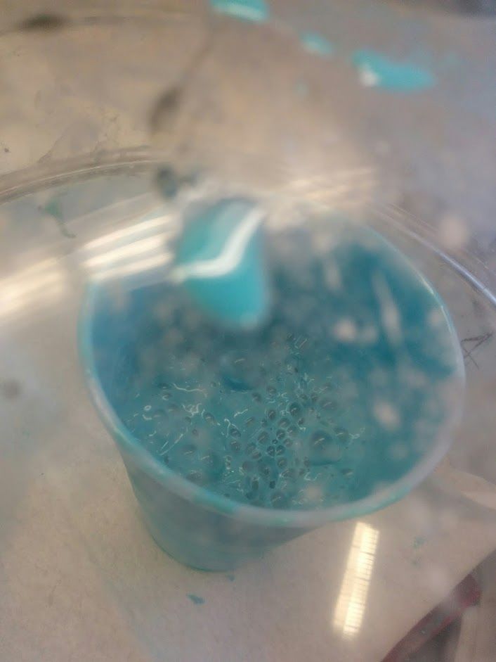
De-gassing in process
You can see all the bubbles coming up
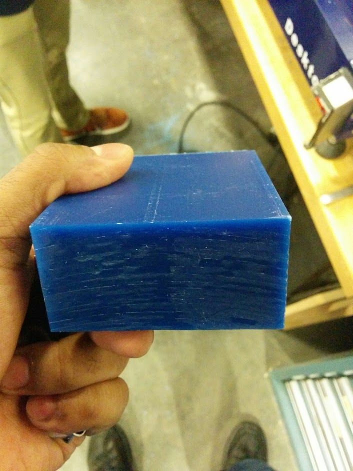
Positive mold
The positive mold is made from this block of wax. Instead of making the negative mold directly, a positive mold is made so so that the negative mold can then be made FROM the positive mold with silicone. Silicone is reusable because it is bend-y and can be deformed to remove the final object without destroying the negative mold. Also the wax is easy to machine
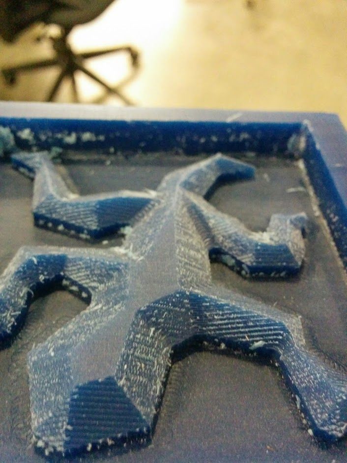
Lizard positive mold
It's a little rougher than I'd like but this can be fixed using a smaller step-over in the finishing toolpath next time
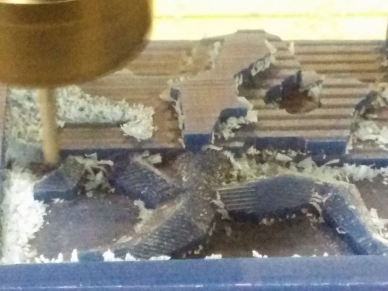
Lizard being machine
This was done using the desktop shopbot!
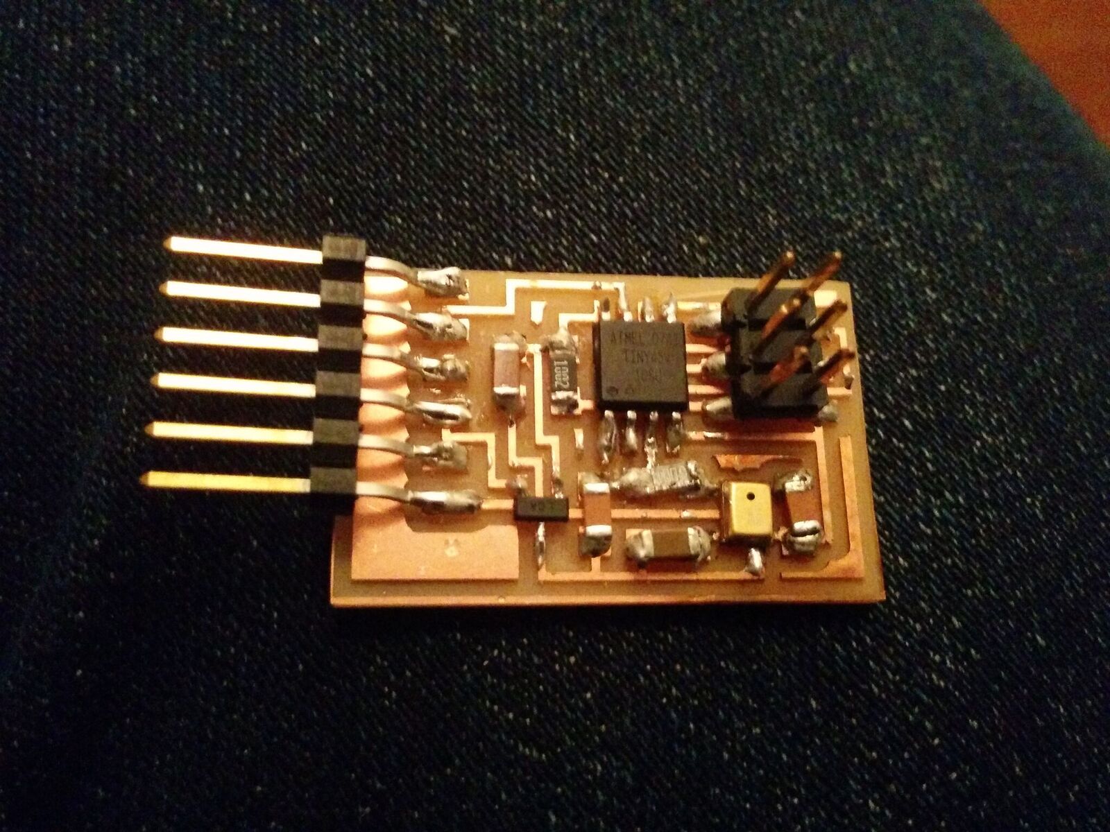
Final circuit - Analog MEMS microphone
This week I was focused on trying to understand the nitty gritty details of how this all works.. How the software connects to the hardware and back. It was quite complicated. I was very lukcy to have Tal Achituv from Fluid Interfaces help me. Here you can see my circuit with the microphone ready to go (the mic was hard to solder and it took me many tries to get it right with the hot air)
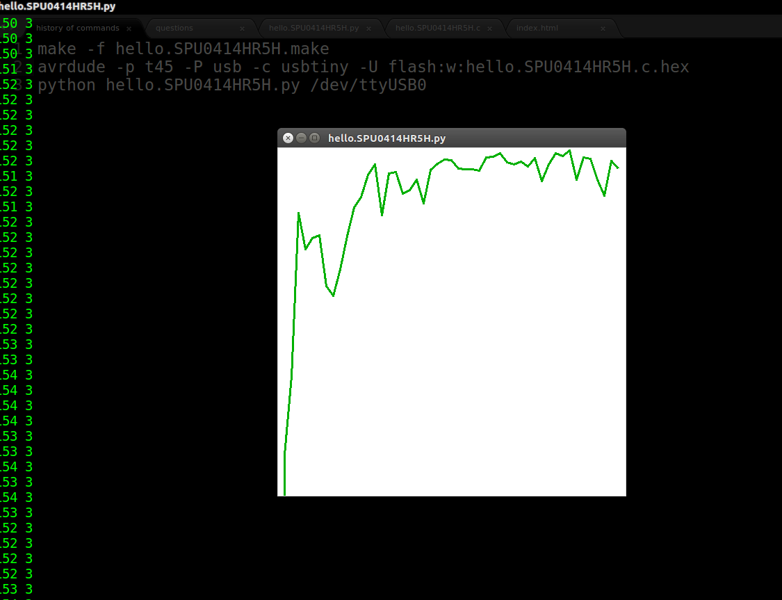
FFT implemented
I was able to implement an FFT on the samples coming in from the microphone. Two realizations from this: 1. the frequency range of my physical voice does not correspond to the actual frequency being analyzed because of how samples are obtained from the mic and then sent to the python code. There are two solutions: a. either understand the mapping between the physics and the code, or b. implement a band pass on the circuit physically. Unfortunately neither would really help because I don't think snoring is a function of frequency..