Circuit didn't work
This week's circuit did not end up working even after 3-4 iterations. Basically there is no response from the chip..
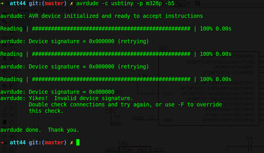
This week's circuit did not end up working even after 3-4 iterations. Basically there is no response from the chip..
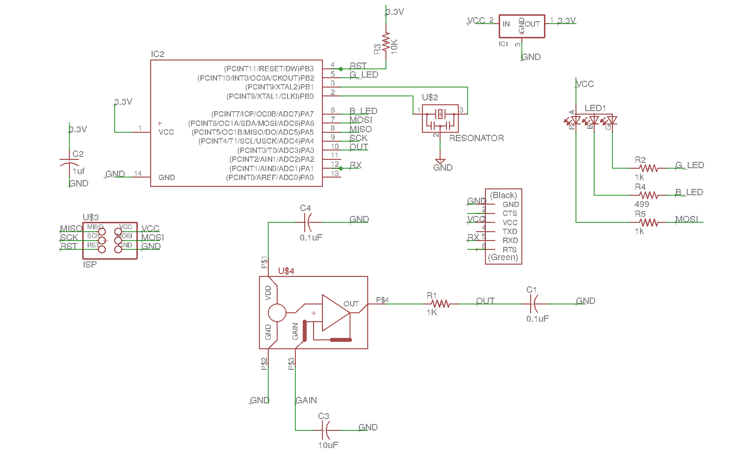
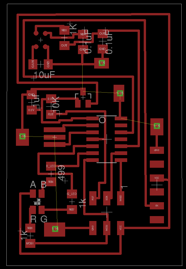
The MEMS analogue microphone requires a 3.3V regulated voltage to work which is fed to it by using a SOT23 LM3480IM3-3.3/NOPBCT-ND regulator (referred to as IC2). I unfortunately wired the 3.3V power to VCC at several positions (including the VCC of the programming header). This caused many issues.
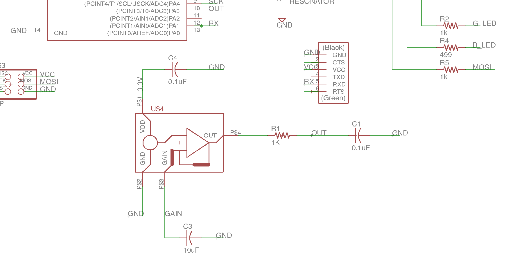
I rewired the whole circuit so that only the MEMS VDD input is wired to a 3.3V input. I hope this is correct?
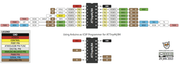
There are only 4 hardware PWM ports on the attiny44 and two of them are MOSI/MISO so I used the MOSI port for LED PWM. Brian said that should be fine for an LED. Not sure what to do for more intensive loads?
I use the MOSI pin for PWM
I have never had this problem but as you can see, the toolpaths are way too deep! I didn't change anything from the defaults and so I don't know what is wrong.
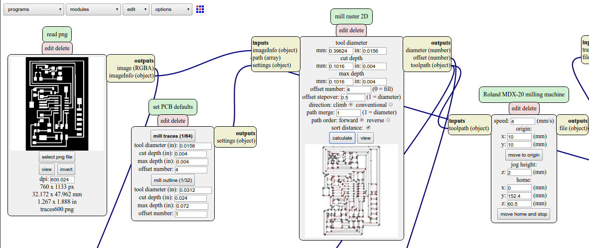
I tried reducing the cut depth to 0.002in but this did not help
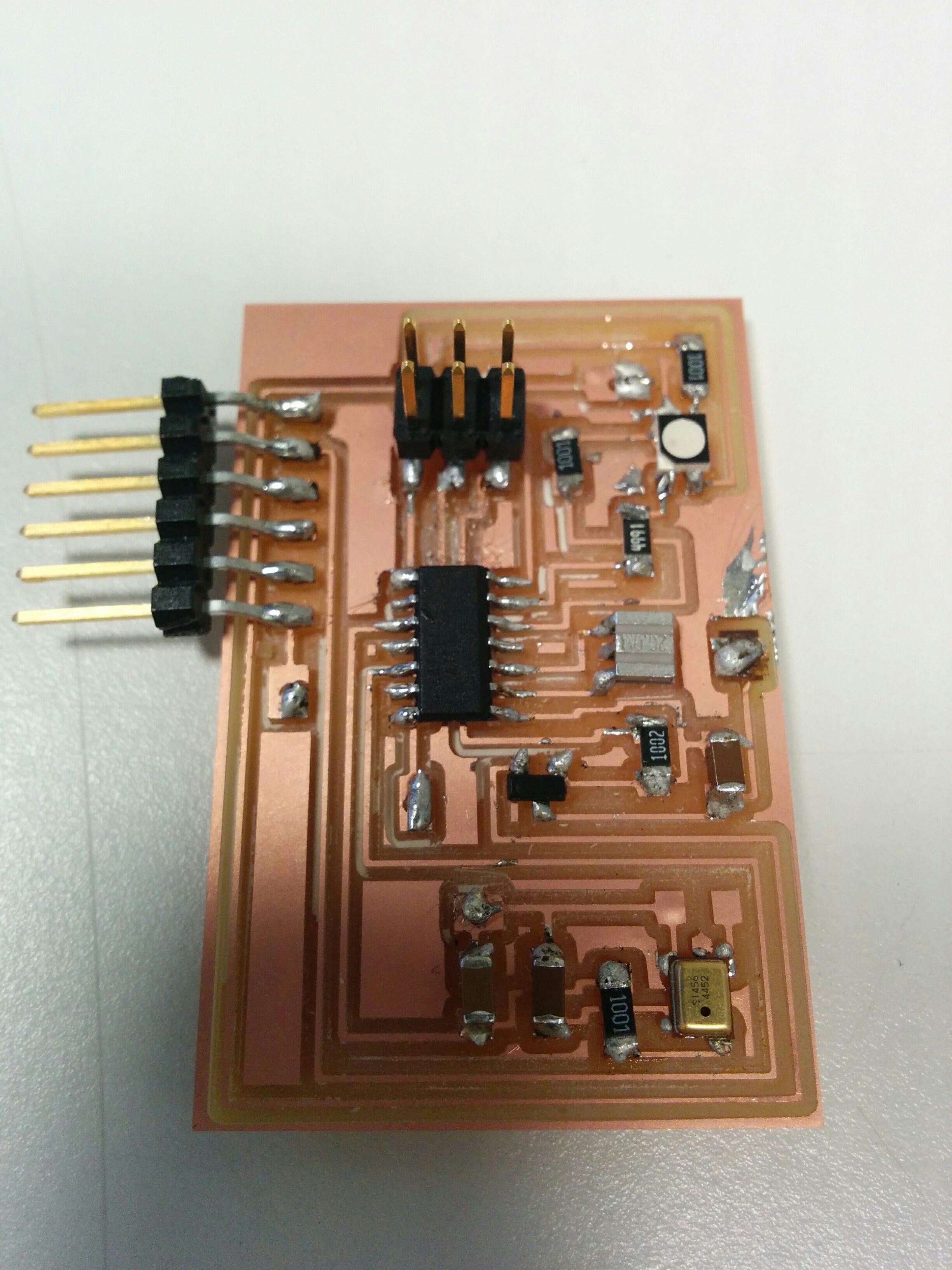
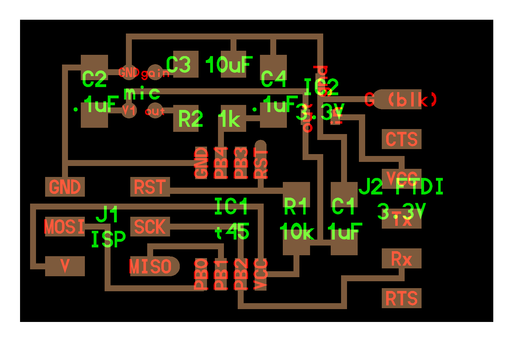
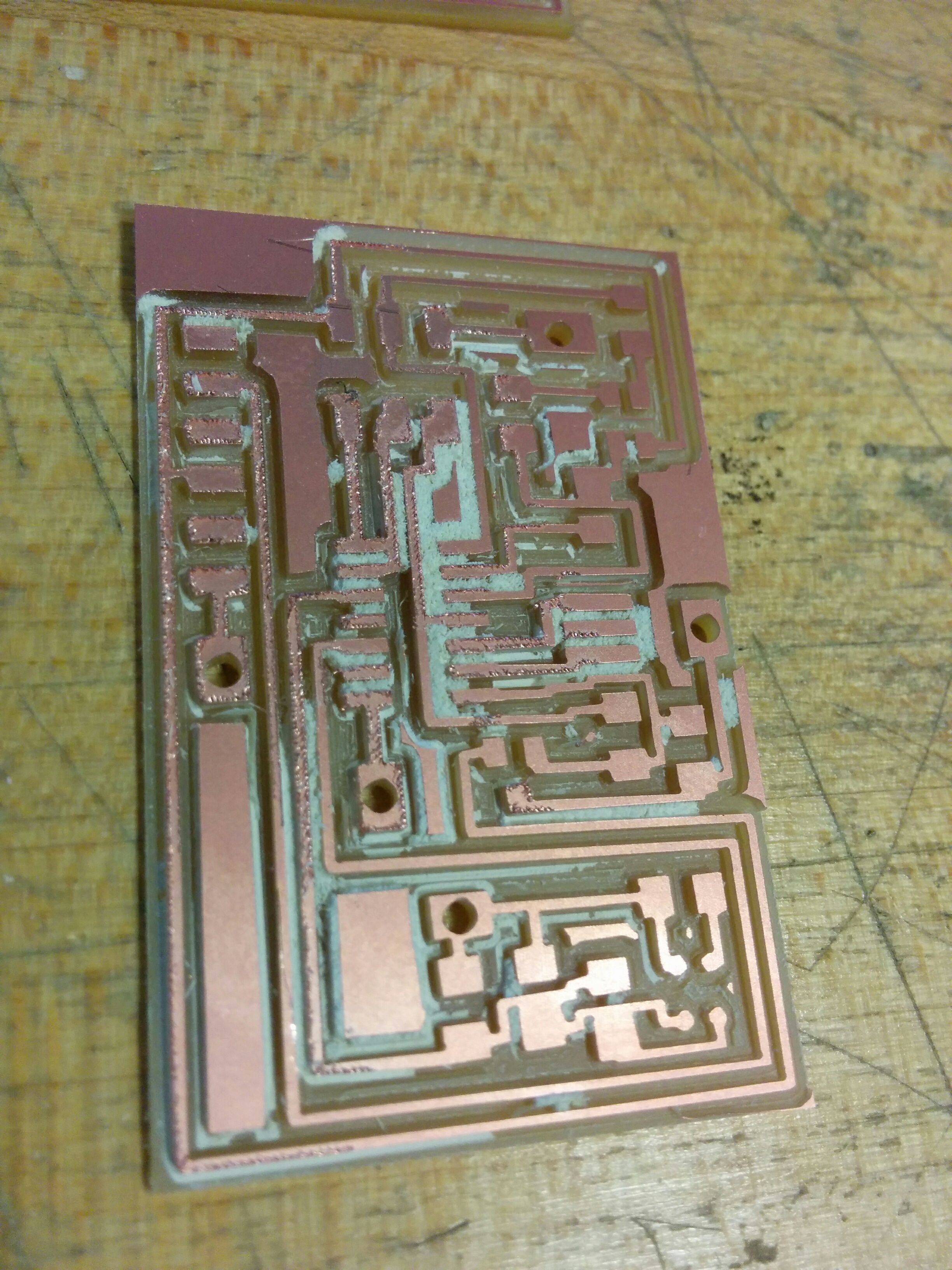
Other than the paths being too deep and it not working (lol), I think my boards finally look a bit more pro! :)
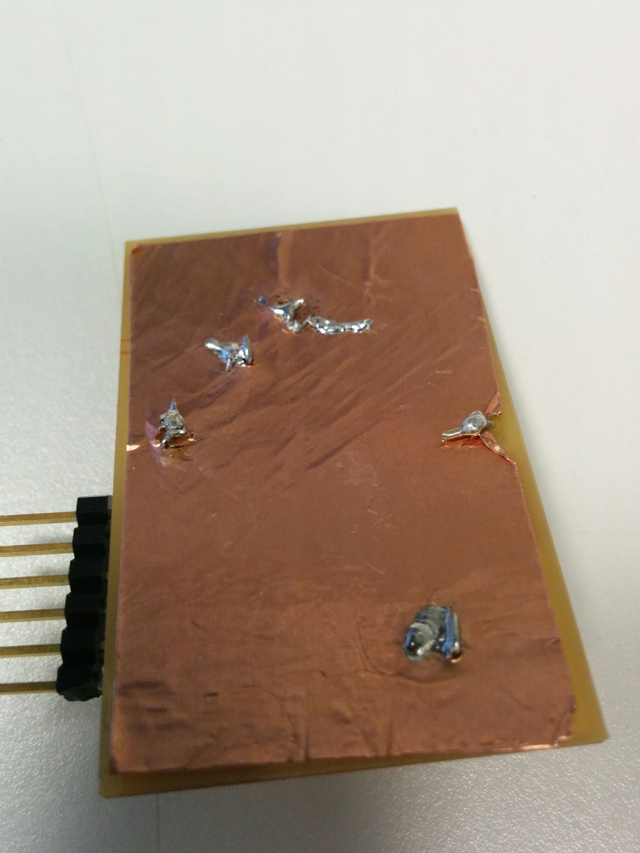
I used the copper vinyl sticker to make the backplate and used wires through holes I drilled to connect the grounds to the backplate

I was not able to simply export the vias to PNG to drill on the mill. I had to export the vias as position, open them as gimp, reduce each via to a point, lie about the diameter of the outline mill to make it a hole. Otherwise it makes a circle-shape trace instead of a punch hole. Surely there is a better way to do this?
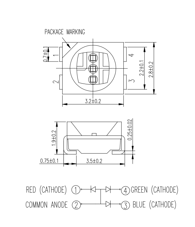
The RGBA on the eagle library and the datasheet are off