Prompt: plan and sketch a potential final project
Project Idea: Cymatic Haptic Pixel for VR/AR
Recent incarnations of Virtual Reality are really dope, and have shown that this is a viable consumer platform. In short, VR/AR are awesome for interfaces. For years, research in science and engineering has been focused on hacking the world, which is a difficult problem. VR/AR instead offers to solve an easier problem, which is to hack human perception. Visually, the Vive and AR devices are making great strides in capturing the whole visual field with effective resolution. Despite the leaps in visual technology, the progress towards haptic feedback is limited to straightforward techniques such as rumble packs placed against different parts of the body. In my project, I want to address the haptic feedback question in a versatile way that hasn’t been addressed before.
I want to work on a haptic pixel which gives the user the feeling of texture / pressure. If this pixel is tracked in 3D and attached to a user’s hand, it can allow the user to “feel” the world. I would like to creat a haptic renderer/display which can dynamically render texture using standing waves on its surface. I imagine creating a 3D tracked version of a chladni plate.
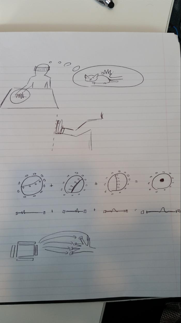
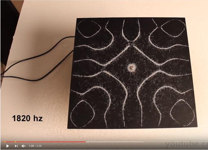
The chladni plate is a sheet of metal or other material which is vibrated by a transducer in the center. This causes standing waves to form on the plate. The nodes and anti-nodes cause sand on the surface of the plate to shift towards areas of non-movement. By creating areas of varying movement and non-movement in 2D, maybe it’s possible to generate different textures.
In the above example, a user wearing a VR headset and touching the cymatic haptic pixel will feel like they are touching a cat. When combined with the visual feedback of touching a cat, the user may even be convinced that the cat is there.
The cymatic pixel can even by tracked in 3D and attached to the hand, so that when the user appraoches a virtual wall, they can run their hand across it and feel it.
In the future, these pixels can be miniaturized with a small number of piezoelectric transducers along the side fo the chladni plate to create pixels for each finger tip.
Many transducers along the outside of the plate can be combined with pre-computed patterns to generate arbitrary standing wave-fronts. In the end, we may see a bump display which can move the peak bump to anywhere in 2D along the surface. This could be used as a miniature shape display which is low cost (with much less 3D resolution).
Visualizing it in 3D:
Blender:
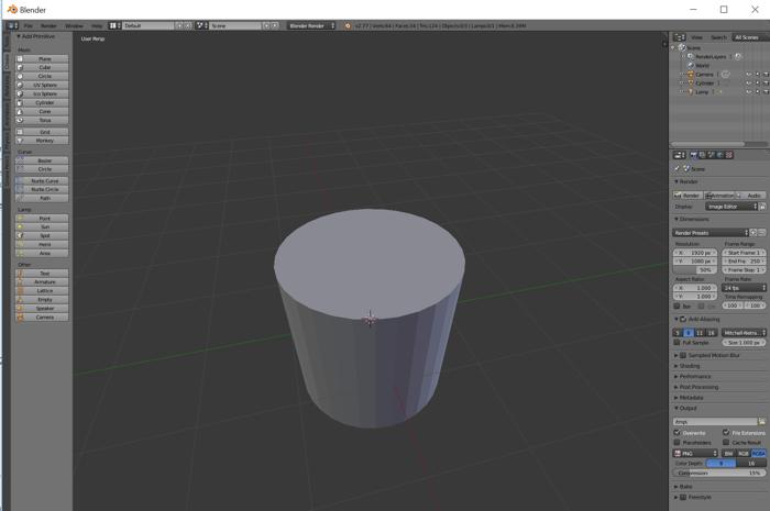
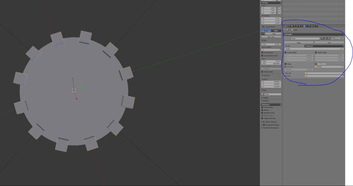
First I made a cylinder:
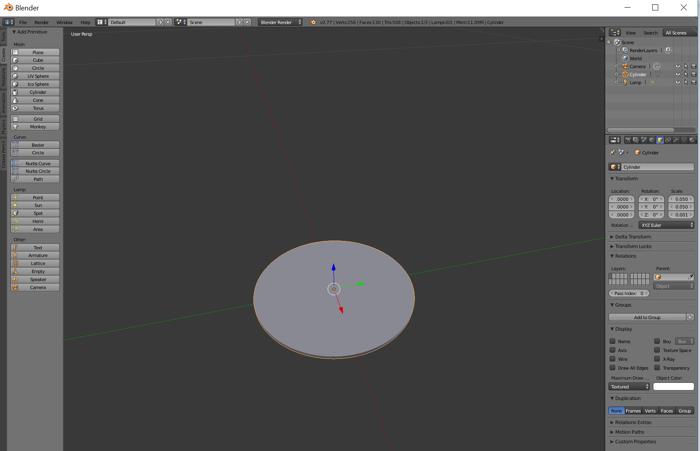
Then increased the number of vertices and changed the scale to 5cm x 5cm x 1 mm. This represents the membrane.
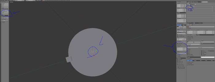
The next few steps get a little tricky. I needed to have 12 cubes on the circumference of the cylinder facing the center. In order to do this, I created 1 cube on the circumference, and set it’s transform origin to the center of the cylinder. That way, when it is rotated, the cube rotates around the outside of the circumference.
I add an array modifier to the cube and set the modifier to an empty-object placed at the center of the cylinder. When the empty object is rotated, a set of duplicate cubes are created.
Man, this part took wayyyy too long. Blender needs a more intuitive way of doing things.
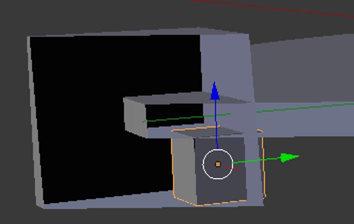
I added another cube to represent the piezo actuator as it sits directly below the rubber.
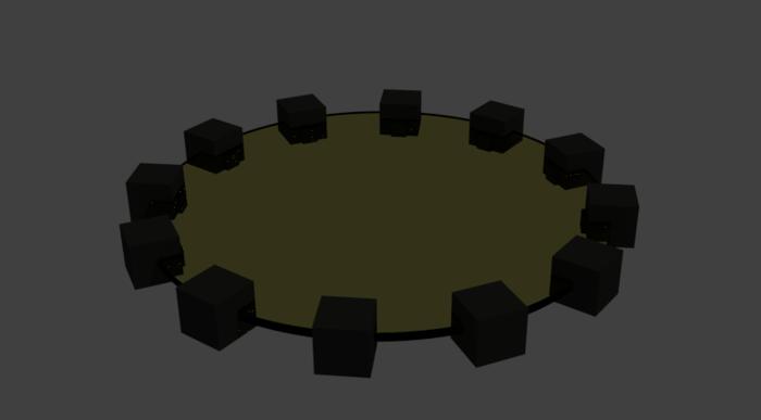
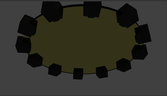
And rendered it using cycles. The center rubber is modeled as glass with IOR 1.45 and yellowish background color.
Updates: 11/16/2016
Updates: 11/22/2016
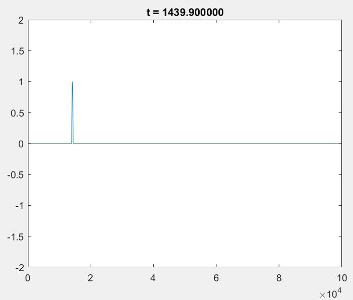
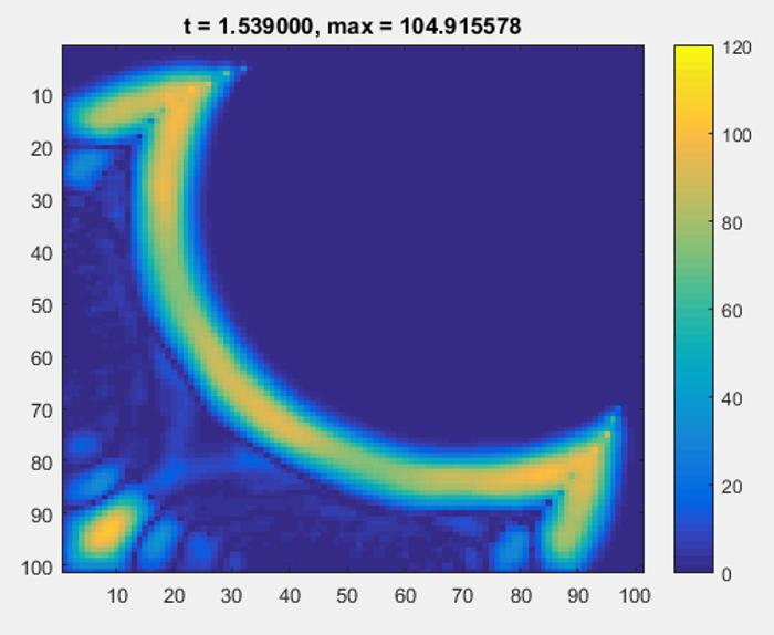
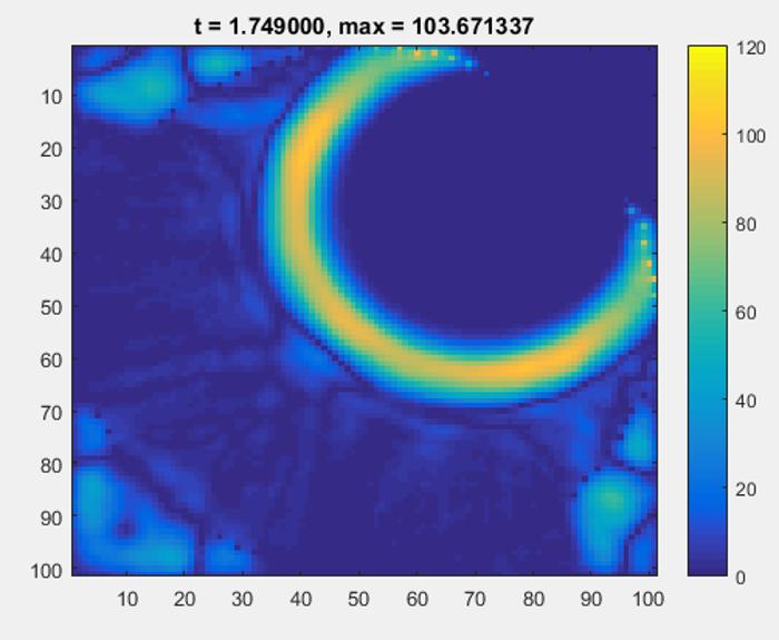
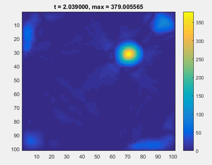
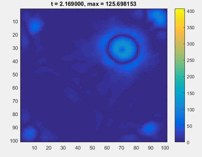
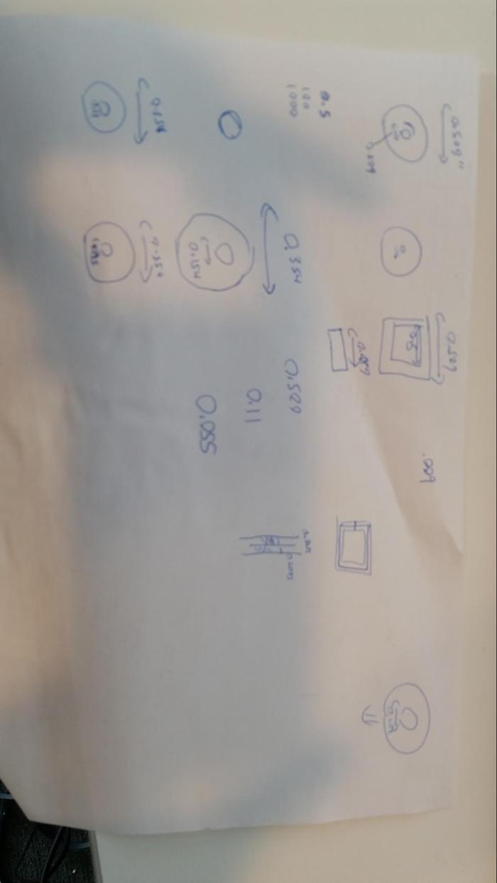
Implementing 2D wave simulation with Control:
The results show that the system can work and focus in transient mode, but in standign wave mode, it is difficult to shift the standing wave nodes. That should be ok though if I utilize a material with a slow enough wave speed that my actuators can move fast enough. Note that the maximum changes between these images, and the SNR is actually pretty good. (this is with 100 actuators).
Updates 12/7/2016:
Updates 12/14/16:
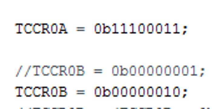
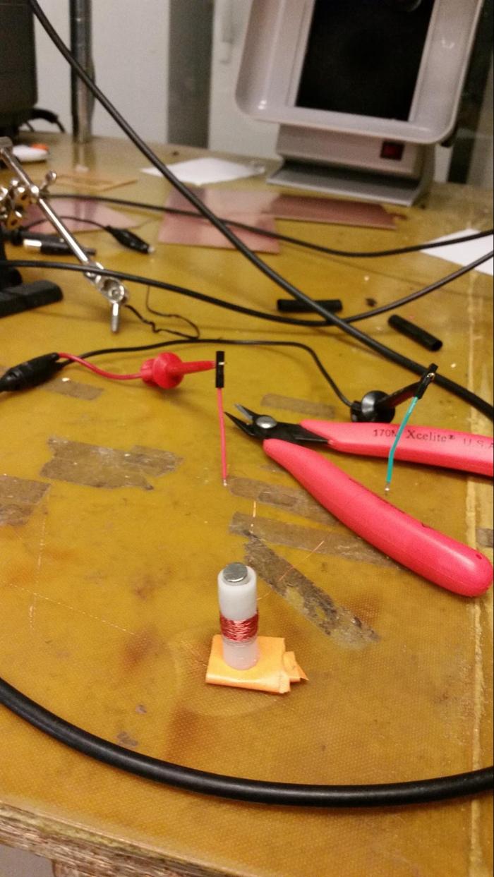
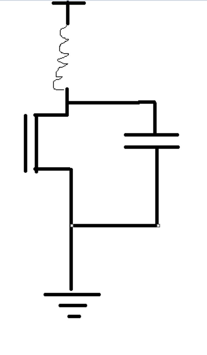
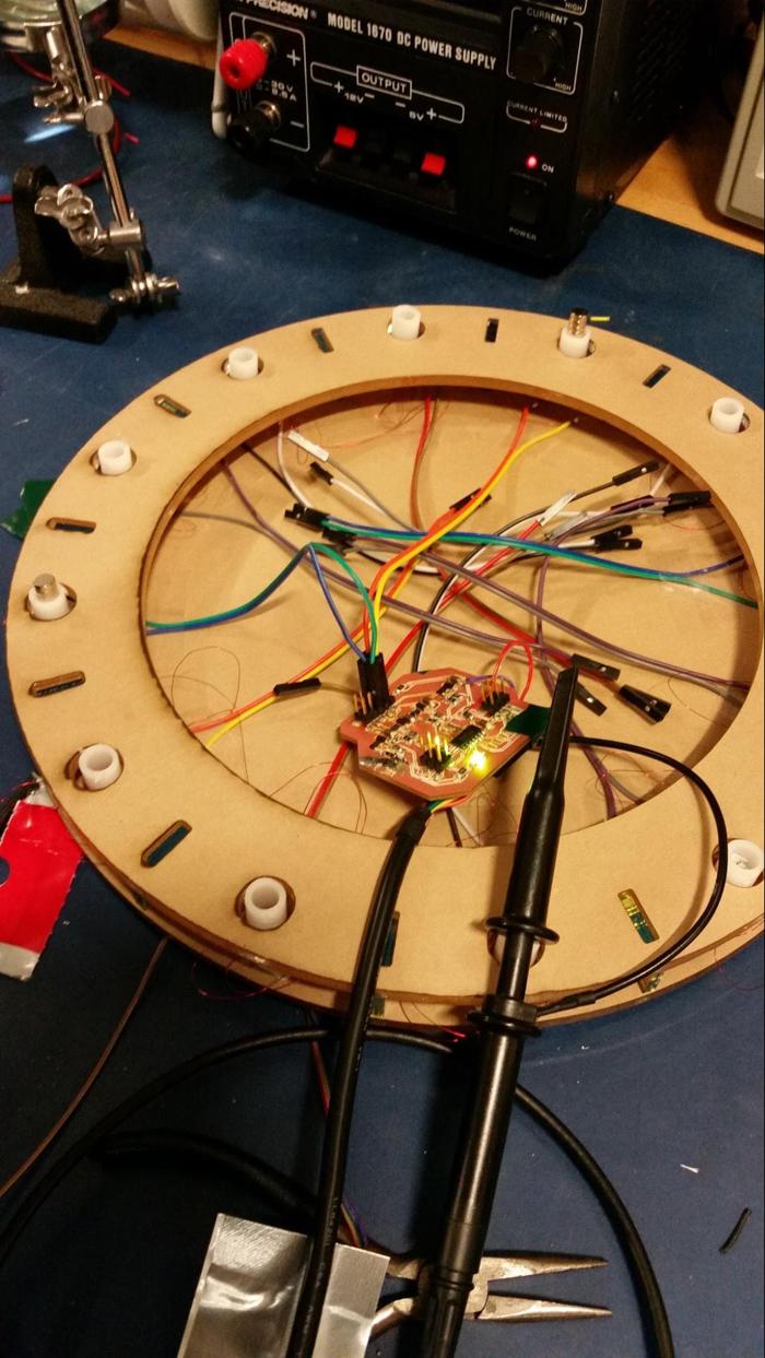
I had some trouble smoothing out the PWM signals. I’m currently using an attiny44 and setting up the clocks so that I can update the pwm at 31khz. The digital signals are going out fine, however I think theres an issue with the the analog circuit (in terms of smoothing). Currently, here’s where I put my capacitor:
However I think it may be better to place it around the electromagnet itself.
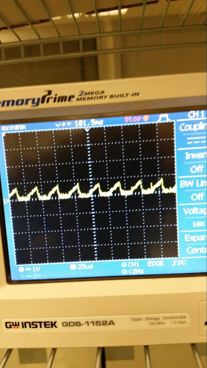
I decided to put the magnet in a pvc pipe, and then wrap the magnet wire around the pipe. Here is what varying the voltage looks like:
https://www.youtube.com/watch?v=jU4TTrSxf4o&feature=youtu.be
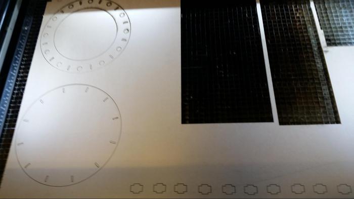
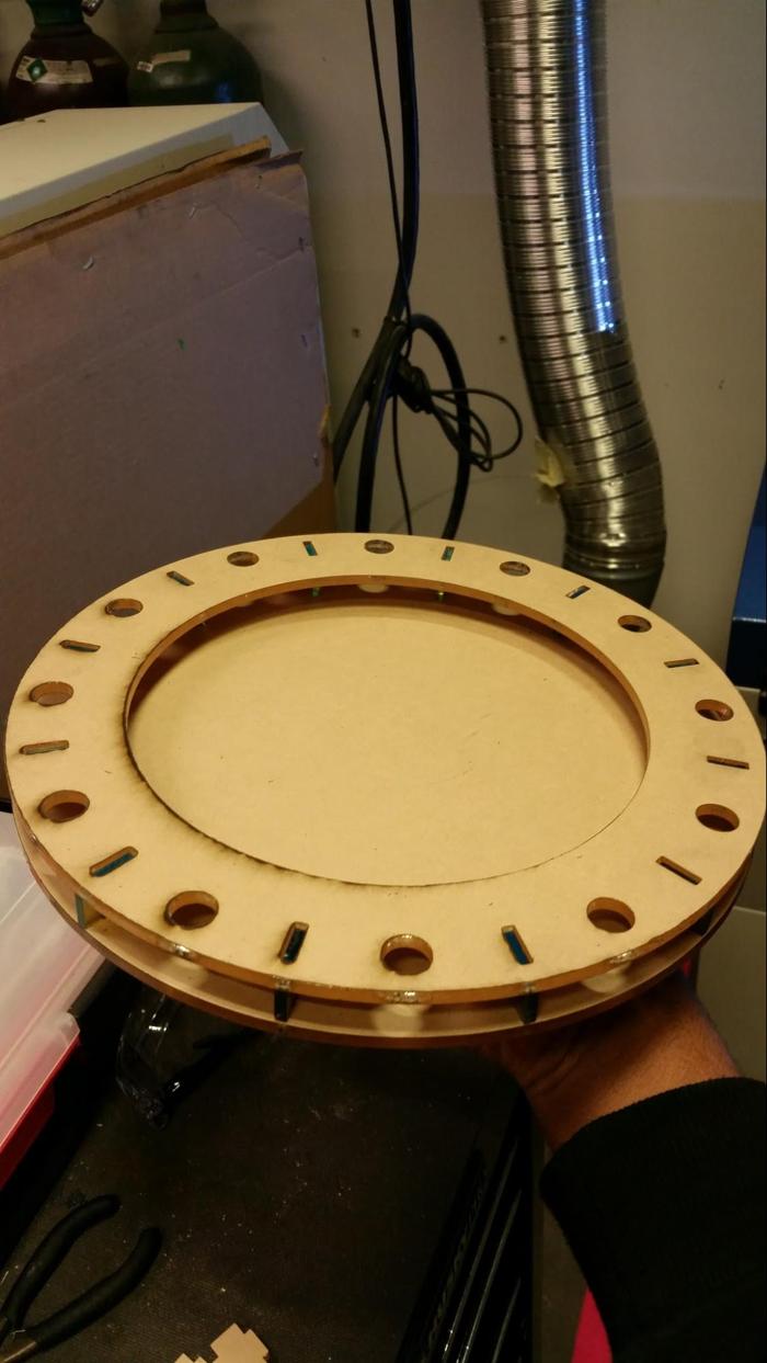
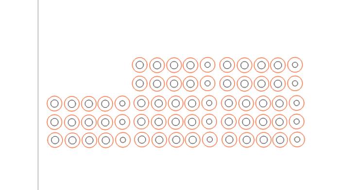
Next it was time to make the frame. I chose to laser cut it because it was available and required less setup than the shop-bot. The result provided good structure, but the circle holes for the pistons were too large, and if I had spent more time figuring out the kerf, I could have fixed that.
An image of the cut out on the laser cutter table.
And an image of the frame assembly. Super simple.
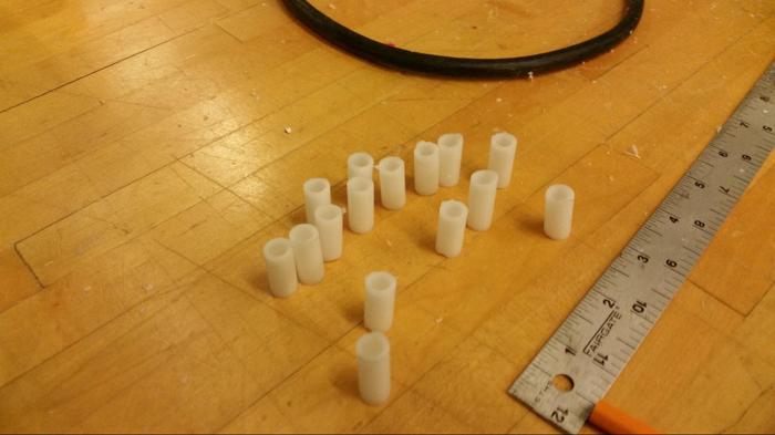
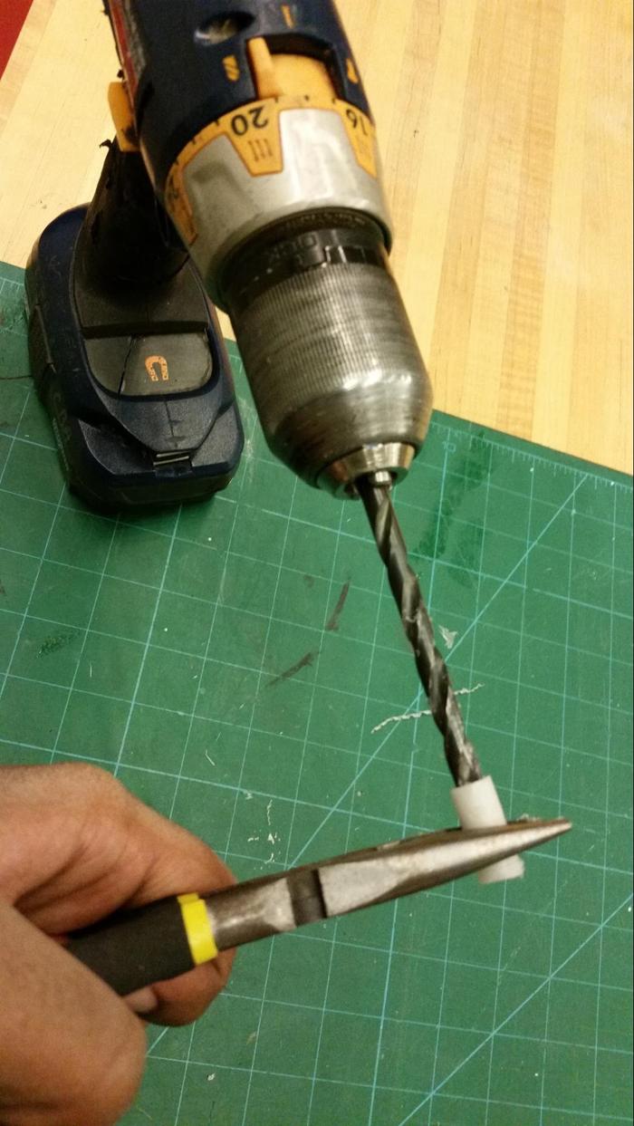
In order for the electromagnets to move, I planned on wrapping magnet wire around a tube and putting the magnets in the center. I cut out a set of pieces of PVC pipe to do this. Getting the pvc cut to be flat was a real challenge. Furthermore, the inside tube needed to be widened before the magnets would slide easily throughout them. It was a real pain.
In the image above, I use a drill to widen the inside of the pvc pipe which would act as a shaft for the magnets to move freely through.
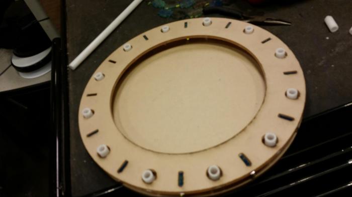
Above you can see the frame assembly with the pvc shafts. Notice how the holes are too wide, and the pvc shafts all have different heights and varying orientations.
The above picture is of the assembly with magnet wire wound around the pvc shafts. I later change the shafts because the pvc idea was so terrible.
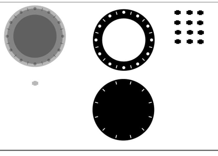
In order to make shafts which easily let the electromagnet slide up and down, I decided to make a shaft out of laser-cut material. The plan was to stack multliple layers of acrylic with the correct hole sizes. Since I have two differently sized magnets, I made an assembly of magnets by attaching wider mangets to thinner magnets. The thinner magnets act as the top part of the piston (and rests a little outside), and the wider part sits inside the piston. The wider magnets are contained by a laser cut piece of material which has a diameter wide enough for teh smaller magnets and not the larger magnets. This time around, I spent a lot of time figuring out the laser kerf and fixing the design.
Above you can see the parts for the pistons, with the mix of large and small diameters. They are colored differently since the laser cutter cuts out one color first (the black). This makes sure that the middle part falls out first.
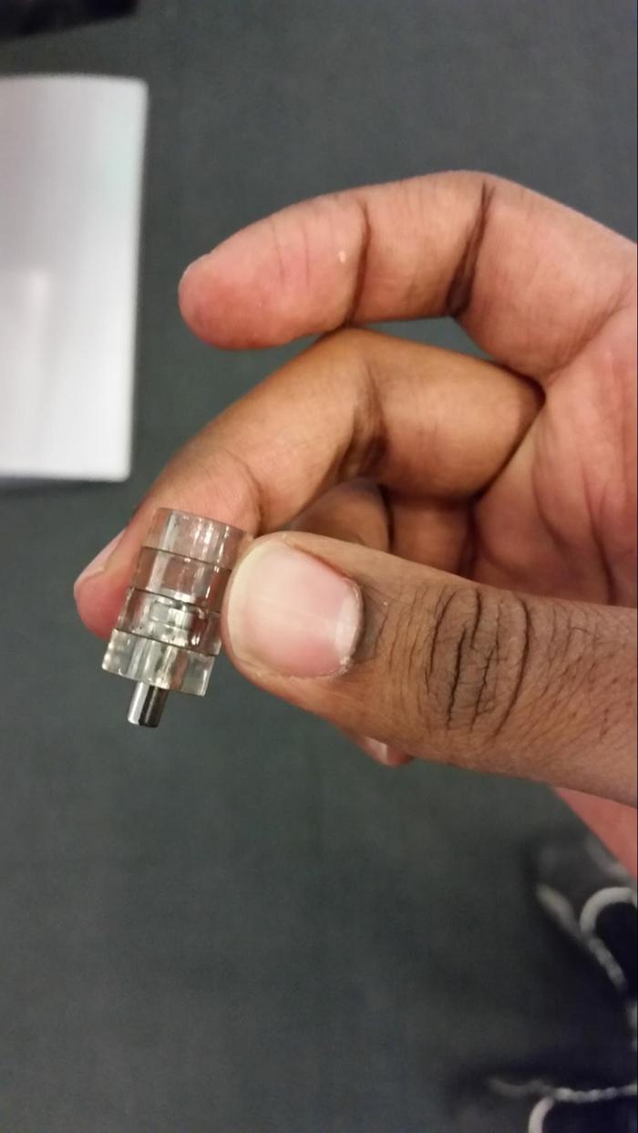
An above image of a completed piston. The magnets fly very well through it. The layers are held together with super-glue.
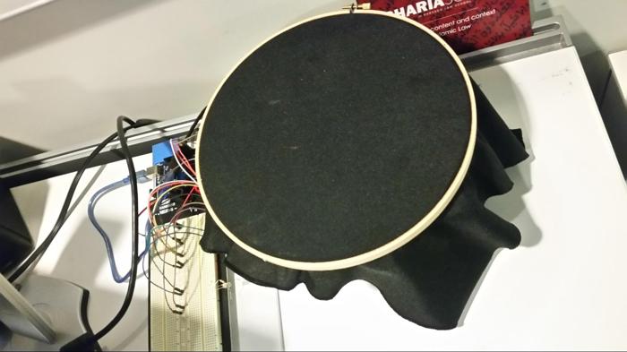
It took a few tries to figure out the correct configuration of layers and electromagnets that was stable, but once that was set, I made 4 of these pistons and placed them in the frame structure.
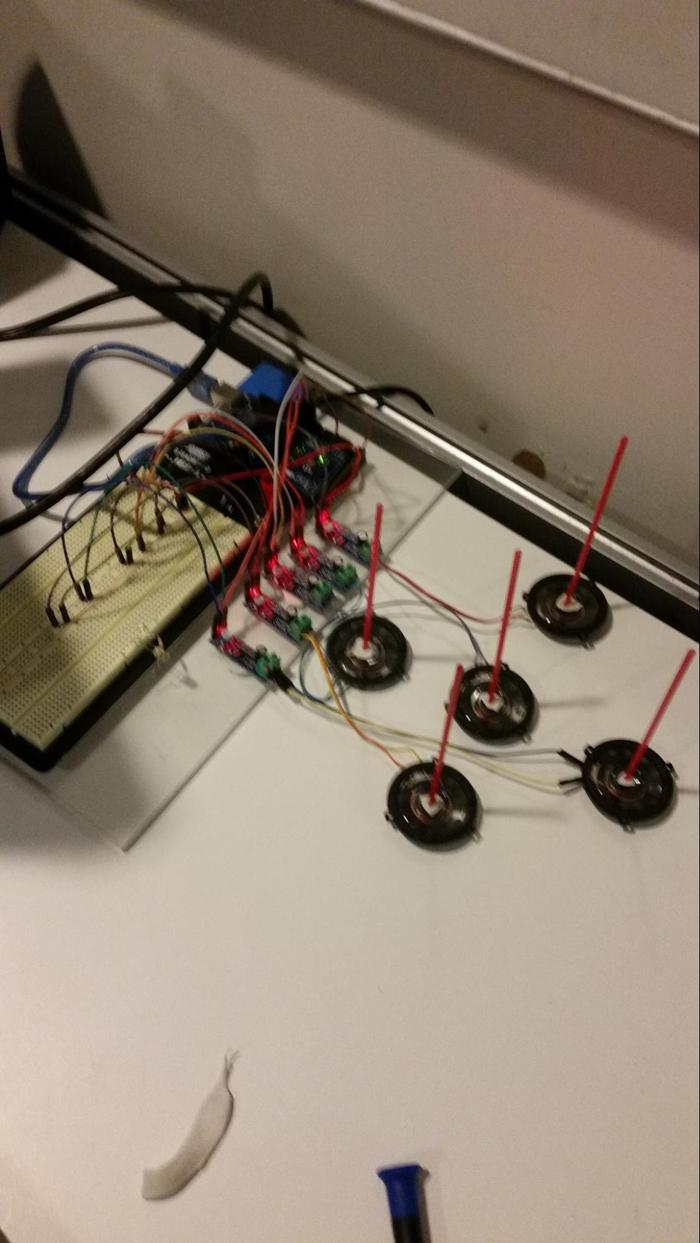
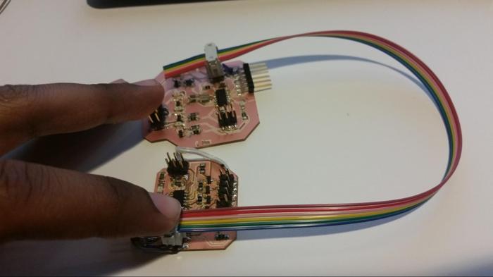
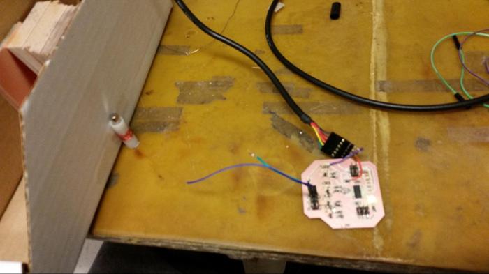
The next step was to fininsh the control system for all the magnets. My project can move 4 pistons (1 board), I didn’t have enough time to make the other boards which would control the other magnets, however the design is absolutely ready for them (TX,RX,GND,VCC,VBB, and SYNC are all routed to a 2X3 header).
Completing the program was difficult because I had to stay within the 4K limit. Furthermore, I needed to use software serial in order to communicate with the attiny44. In the end, I was able to program things with 3.6kb. I’ll post a link to the code in a bit.
Video of 1 piston working:
Video of piston working inside the frame structure
Video of 4 pistons working in the frame structure
*** youtube ***
Video of pistons working with the Unity interface
https://youtu.be/8tlolnByX3E
The final result allows me to control 4 pistons with frequency and phase. The pistons have been tested up to 30hz. I wasn’t able to achieve the simulated effect that you see above, because I didn’t spend the time to determine the wave speed within the material. That being said, it will be an interesting starting point to get to a system that can focus the wave to any point along the membrane. In the future, I would want to use speakers instead of custom made solenoids.