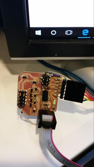
This week I designed a circuit that would allow me to control 4 speakers simultaneously. I made the circuit with multi-drop in mind, so I could control 12 speakers by daisy-chaining 3 of the circuits together.
Fabricating the circuit was quick. The biggest mistake I made was brining the outline too close to the traces, so they ended up cutting through some of the traces. Nothign 3 wire jumpers don’t fix. But it required extra special soldering and checking my work with a multimeter while I was going.
Burning the bootloader for the circuit worked, however when I went ot program it, I received the following error:
Essentiallyl, the error said that there were issues with parsing the board.txt file. I tried a lot, but what worked in the end was resintalling the arduino IDE.
Next came programming the circuit. I wanted to control 4 speakers with a single circuit, so using the hardware PWM library from arduino wasn’t going to cut it. The way I got around this was creating my own hardware-based PWM that took advantage of the timers.
I learned a lot fom this link: https://learn.adafruit.com/multi-tasking-the-arduino-part-2/timers
I first set up an interrupt for Timer1, however this ended up conflicting with the Software Serial library i was using for communication. I moved on to trying to measure the microseconds elapsed to trigger the various elements.
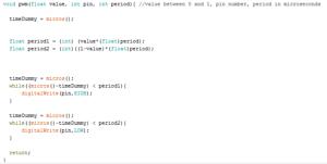
My first try is shown below. It utilizes the micros() function to count microseconds.
I tried out everything on an LED first. This led to a very quantized result (good timing, but only 4 LED values). I’ll get back to what went wrong here.
In the mean-time, I had a considerable issue with programming space. I realized I was doing a lot of floating point math, but still, I ended up running the program up to 4k pretty quickly. One of the worst offendign lines is the following, a calculation for the wave value. The reason it took up so much space is that there were conversions from unsigned longs to floats. In addition, the bootloader and software serial library were taking a heavy toll on my programming space:
//float value = (cos(2*3.14*frequency*t - phase*3.14/180.0f) / 2.0f) + 1.0f;
Fixing the wave values:
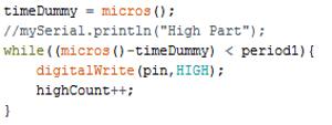
Like I mentioned before, the wave value output for the “wait and change” method were not great. The code is shown below:
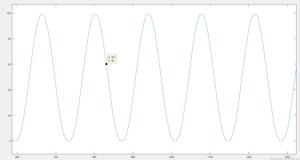
The result for the period of wait time should theoretically result in the following graph:
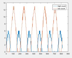
However when I measure the count, I get a graph that looks like this:
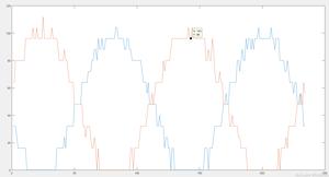
I kind of banged my head against a wall for a second, but I noticed that the high count were heavily cut off, while the low counts were fine. It ended up being that the micros() command needed to warm up before it could be reliably measured. So I introduced a warm-up where the command is called over and over before the PWM is outputted. The corrected count is shown below:
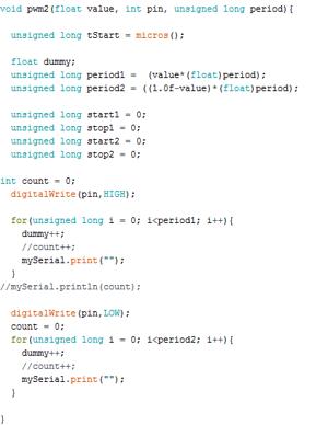
But that’s not good enough, still heavily discretized. The reason it’s so quantized is that the micros() command is only accurate to about 16us. In order to fix this, I tried another pwm style. Here I would pwm blind by just performing operations (without timing them). As long as the ration of on/off was correct, things would work.
That function looks like this:
That worked!
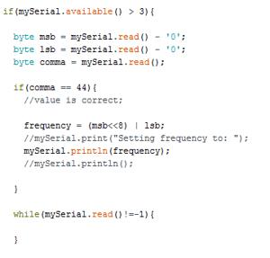
Now that I had that working, I connected via serial to Unity. For serial, I wanted to send the frequency of the beating of the LED by sending two bytes, followed by a comma. The code for reading a serial command is:
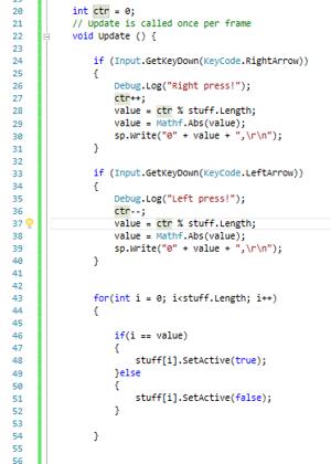
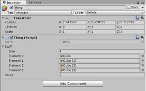
On the unity side, I set up a series of cubes with differing textures. Whenever the user presses right or left, the correct box is set to active, and the others are disabled. Then the unity app sends a message over serial to change the LED beat frequency. Here is the unity code, attached to a game object:
You can see a video of the result here: