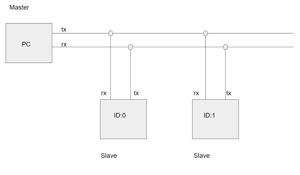
This week, I implemented a simple multi-drop serial network where the PC (master) communicates with multiple boards (slaves). This matches the architecture for my final project. When that was done, I tried to extend it so that some of the boards could communicate with the other boards (didn’t end up working).
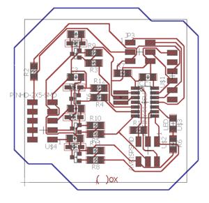
I designed the following boards using the ATTINY44. The board is capable of PWMing 4 different speakers / voice coils. My intention is to combine 3 of these boards to control the standign waves in the membrane for my final project.
The 6-pin network header has:
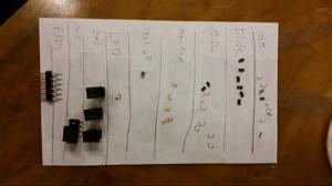
For the first time I used the “put the parts on a piece of paper first so you don’t have to go back and forth between soldering and picking up parts” (ptpoapopfsydhtgbafbsapup) method. You can see how cool it looks below:
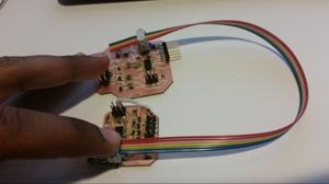
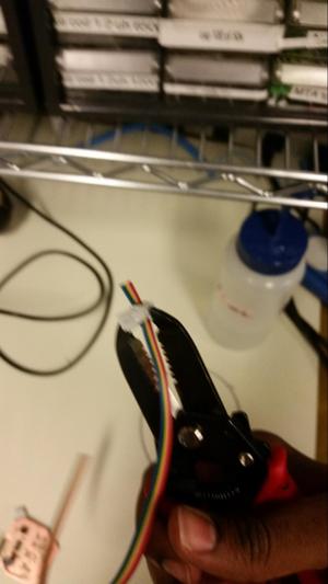
After finishign the board, I put together the multi-drop network part. In order to do this, I took a ribbon cable and put in a 3-headers spaced apart. The headers have 0.1” spaced teeth on the back, and these bite into and surround the wire of the ribbon cable. The technique is pretty stable, but annoying to get to work at first. The best practice I found was applying force with your fingers to the back of the ribbon cable onto the back of the header while the header rests on a flat surface. Then, placing the backing of the header on, and tightening it with a plier-like tool (longer the pliers the better).
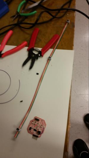
The resulting cable:
I didn’t put care into making sure the cable woudlnt’ blow up the board if it was reversed, i shoudl do that.
The first order of business was connecting everything together and addressing teh boards. I wrote code that gave each board an ID (0 or 1), and enabled them to flash based on the following protocol:
“01”
Where the first character is the board id, and the second character is the number of times to flash. The resulting video of that is here:
----- youtube video -------
Since that worked, it was onto the next one (getting the systems to talk to each other). I wanted to have each of the boards alternate between being master and slave (utilizing the same wiring). One board would start counting from 0, pass on a 1 to the other board. That board would flash 1 time, then pass a 2 to the first board. The first baord would then flash 2 times. The first board woudl then pass a 3 to the other board. The other board would then flash 3 times. They would go back and forth until they reached the number 10.
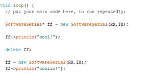
It was a big challenge to get boards to switch between master and slave mode because they are wired to be RX and TX. Furthermore, since I was relying on the Arduino Software Serial library, I was limited in the implementation. Fundamentally, I needed the board to be able to dynamically switch which port it used for TX and which port it used for RX.
The first thing I tried to to was declare the software serial object as a dynamic variable. The issue with this was the RAM size on teh ATTINY44 was not large enough to sustain this. Furthermore, the delete operation was not able to remove the pointer. There were also other issues with the library which would cause unpredictable behavior from the ATTINY and restarts.
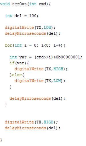
Since the software serial library was not enabling me to switch pins in order to get a board to transmit, I decided to write my own transmit function by hand, and utilize the software serial library for receive.
This worked OK for transmitting from a single board to the PC, but it failed to transmit from board to board. At this point, I think I can pinpoint the issue to be the software serial implementation of the receive function. This can be tested by writing receive function to see what it’s doing differently than the software serial library and the FTDI cable’s receive UART.