FAB ISP
This week, we were creating a programmer which we programmed with a programmer which will eventually be used to program microcontrollers and other programmers. The point is: in order to program small Atmel chips, you need a programmer. The class is all about making, so we are making a programmer for Atmel chips.
I’ve had tons of fun in the past etching circuit boards with terrible chemicals, but this week we’ll be doing the mill method. Using a computer controlled mill, we will cut out a circuit board from copper-clad FR2. This method is slower, and the resolution is lower, but it’s as easy as hitting “print” and doesn’t hurt the environment.
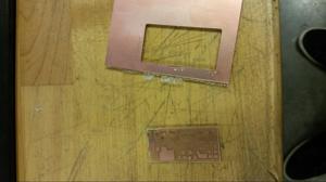
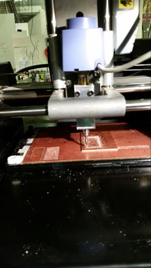
The circuit-board was cut in two-passes, the first milled out the traces, and the second cut out the board from it’s shell. Here is a picture of it happening in action:
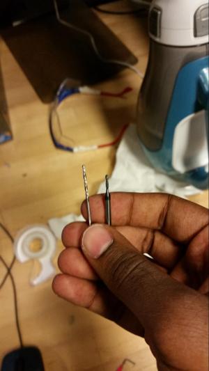
We used a 1/64” bit to mill the traces, and a 1/32” drill to mill out the board. The board is cut out with a 1/32” drill, which led to the MAJOR problem with using the modella. The modella uses 2 set screws, so it is difficult to align a bit. It is thus necessary to use a bit with a wide diameter whcih fits snugly into the slot. This enables better alignment. Below you can see the first 1/32” bit I tried to use and the one I eventually switched to.
Another weird thing I encountered with the modella mill is that the mill spins whenever you try to adjust the height of the tool. This is really dangerous (or time consuming) and makes it difficult to swap bits.
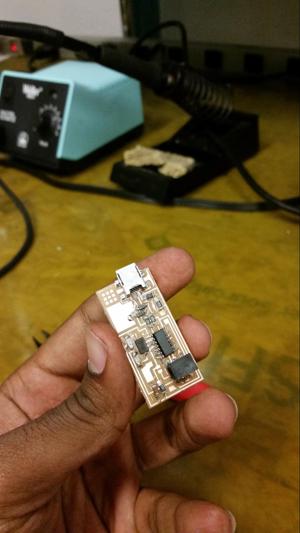
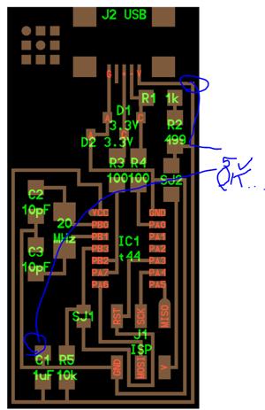
After cutting out the board, you can see that all the traces are intact. The next stage is to solder the components to the board. There were no major hiccups here.
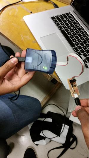
In order to test to see if the board was working, I connected an AVRISP2 programmer through the ISP interface (6pins). The main LED on teh programmer turned green, indicating that it could communicate (or identify) the chip on the board. This was a good sign.
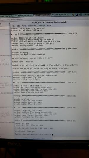
Following the instructions on the FAB class site, I was able to program the board’s firmware. The system gave the all-OK for communication.
However, after programming the board, I ran into the issue of the board not showing up as a programmer when it connected to the USB. When the board is plugged-in or pulled-out from USB, a kernel-level system message should show up in dmesg, but it didn’t. Also, the board didn’t show up using lsusb.
So how could it be possible that the board could communicate with the AVRISP2 programmer, but not communicate via USB? First things first, I checked the power supply, and it was indeed at 5V while plugged into the USB.
Then I though tthe issue could be in communication with the board. I redid the soldering for all the resistors and capacitors, since these form filtering networks for the communications. Still no dice. I also redid the soldering for the usb traces.
I got stuck here, and the plan is now to connect an oscilloscope and measure out the signals to see if they are still coming through.