This week, we were practicing embedded programming by programming the boards we designed earlier. I originally designed my board with a capacitive touch sensor pad, and I hoped to get that pad working. However, I didn’t end up getting everything working in time. Here’s a log of a bunch of stuff that went wrong.
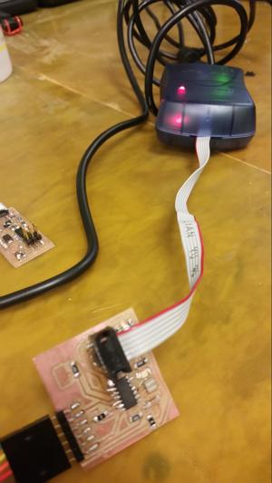
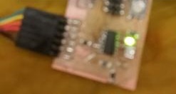
The first thign I did was attach the board to an AVR-ISPII programmer. At first the green-light came on, indicating that the board was receiving power. However, after trying to program, I received an error from AVR-dude that there was a MOSI error in communication. This led the light to flash red on the programmer.
A tip from the TA Ali Shtarbanov showed that the board connections at the chip were not stable. He suggested I use the microscope to track down the errors.
I was perplexed because the multimeter showed that the connections were solid, but it may have only shown that because I was pressing down with the pins of the multimeter.
The chip was removed using the heat gun. The technique is:
*Pick up the specific part with a set of tweezers
*aim the heat gun at the board until the part falls off
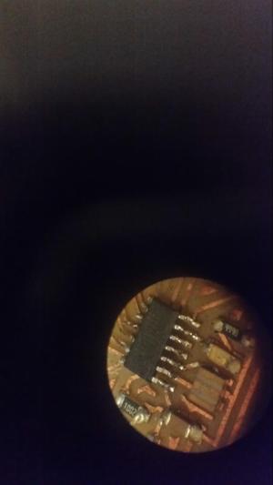
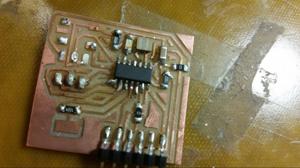
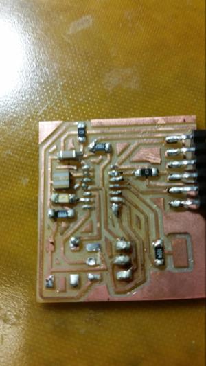
Upon resoldering, I checked the connections with a microscope to verify that they were solid. Although it looked ok, it actually took a few rounds with the microscope to make sure.
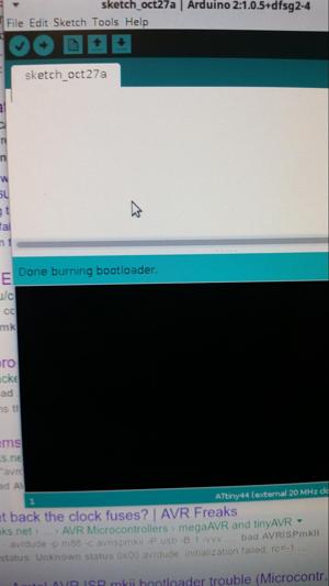
Once the board was in place, I tried to program it with the Arduino bootloader. To do that, I opened up the arduino, selected the AVRISPII as the programmer, and the ATTINY44 with an external 20MHz clock as the board. I pressed “burn bootloader” and the process worked.
However, when I tried to do anything wtih the bootloaded chip, nothing occured.
I was convinced it must have been a specific chip problem, so i replaced it with another ATTINY44, same issue.
So I figured, maybe it’s a problem wtih the bootloader, so I tried using the makefuse instructions that were associated with the echo board from the class site. That didn’t work, so I replaced the ATTINY44 again.
The next time, I figured that there may be an issue with the fuses themselves. In the end, it was that I was setting the board to communicate on 20MHz with an external clock. Initially the board communicates with an 8mhz internal clock. There must have been a problem with the 20mhz external clock, because as soon as it tries to run with it, the board stops and fails to communicate. My guess is that there is something wrong with the clock signal.
The oscilloscope was unable to pick up any clock signal, however, this could be due to the capacitance of the probes. I’ll need to resolder the clock to see if it can be fixed and find a way to measure it
In the meantime, I replaced the ATTINY44 one last time, and programmed it with an 8mhz internal clock bootloader. I then programmed the light to turn off when the switch was pressed, which worked. I want to communicate serially with the board, so I will next work out the software serial protocol with the tiny, because there is no hardware based serial.
After that, I’ll connect the capacitive touch pad.