Week 13: Network Programming
This week we had to connect 2 processors together using some sort of protocol. In my case, I wanted to be able to send commands using Wifi to a microcontroller.
Idea and Research
The general idea was that I would be able to send wifi signals into a microcontroller and this would interpret them to perform some sort of action. I went to the lab to check out the hardware that was available and found the ESP8266MOD Huzzah Breakout board. This board had the class's 8266 Module already integrated with an Atmel microcontroller. I soldered the breakout pins unto the board to be able to connect an FTDI cable and test that the board was working correctly. The simplest test was to power it, reset it, and set it unto programming mode.
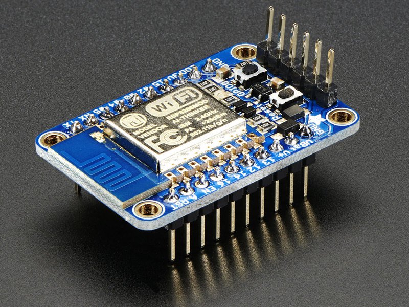
ESP8266 Board (Image from ADAFRUIT)
My Board
Based on what I was seeing, I thought that I would be able to send, through serial communication, a trigger into a simple ATTiny44 board and be able to toggle an LED. I set out to design a board that would have pads to solder the breakout board and connect it with the main circuit. I also decided to use the FTDI header to be able to talk to both the ATTiny44 and the ESP board. This would later come back to haunt me as reversing the TX and RX In one of the connections, nulled it for all of them. I wanted to have the outline of the entire board, but I could never find one that was the one that I already had. This is the board design:
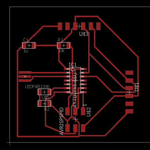
Weekly assignment board
Board Production
After this, I went down to mill the board and stuff it. This was fairly straightforward, same as the other weeks. Since the ESP module was floating, I decided to cover it with tape as per a suggestion from a colleague
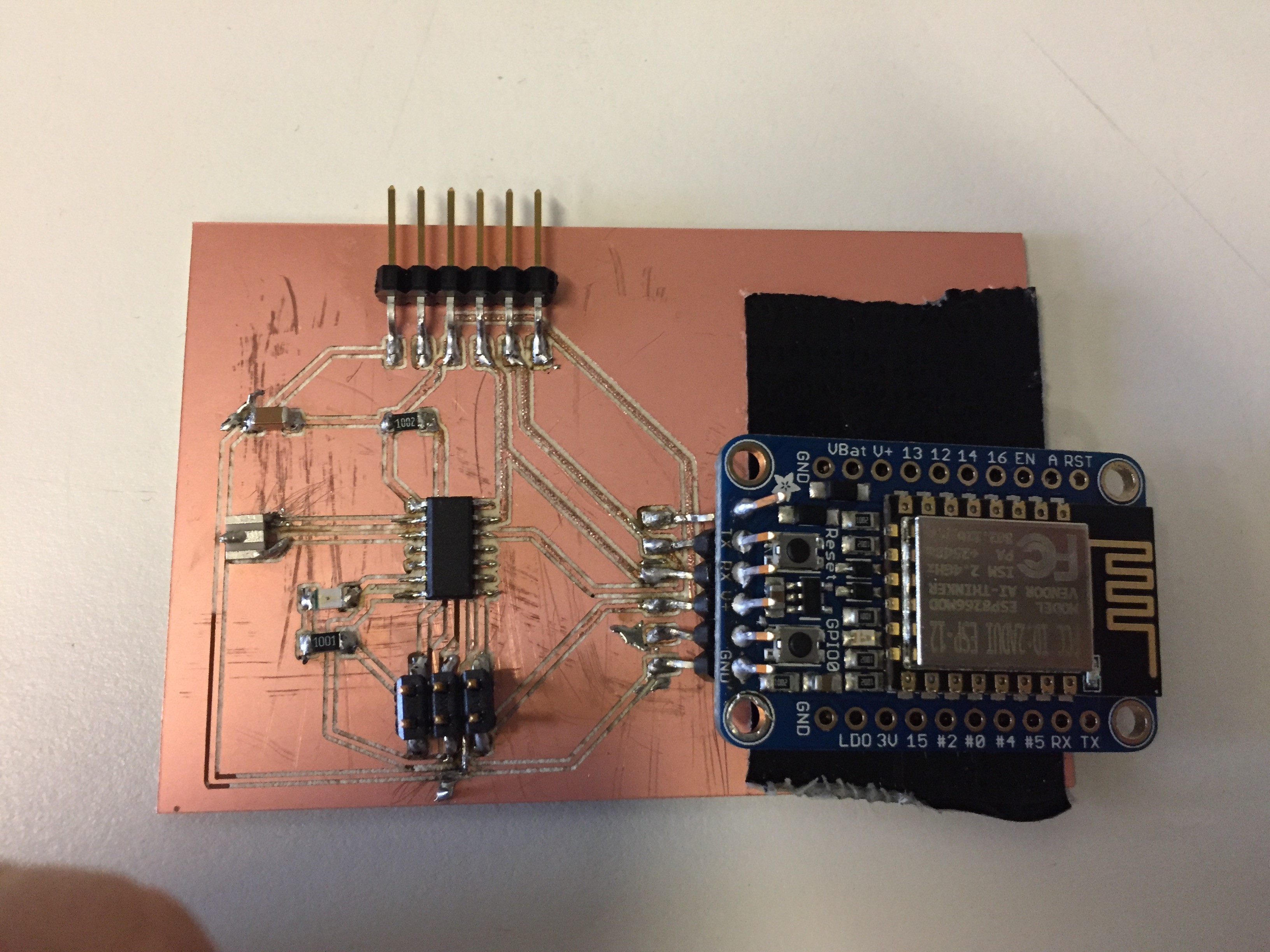
Final Board
Software
I reused some of last week's code to be able to interpret a character that came in serially. That was the easy part. Soon after, I decided to test programming the ESP board using the FTDI, and found that I was not able to communicate with it no matter what I did. After some thinking, I realized that the connection with the ATTiny must be interfering. I set the ATTiny's serial pins to high impedance and as I thought, I was able to communicate with the Wifi board. After I was able to communicate with the board. I looked online to find a tutorial on how to set up a webserver on the board. I found a nice tutorial here/ I modified the code found in the tutorial to send out the signal that I Was waiting on the ATTiny and tested that I was receiving it on the computer. Once I had this, I re enabled the communication on the ATTiny. It would not work! After some thinking, I thought maybe I should reverse the transmit and receive pins. Initially this didn't work. As I was trying configurations, I realized that where I connected the FTDI made a difference, and after connecting it to the power supply (board pins) connection, I was able to get the server up and working.
Working at last
Lessons
Here are some of the things that I learned
- Check that RX and TX are aligned properly aligned between the boards that you want to communicate (should be reversed)
- Webservers can be set up in tiny boards!
Files
Here are the files that I used to program the board.