Week 3: Electronics Production
For week 3 we had to mill a printed circuit board (PCB) and solder components unto it. The finished product was a programmer board that could be used to program other Atmel Microcontrollers.
Initial Experience
After the mill training we received, Randi and I went over to the CBA shop to try to mill our boards. We were able to mill an initial board successfully without any problems. However that is where it all went wrong. After this, we milled unsuccessfully almost 4 boards.
-
Here were the problems that ocurred:
- We didn't secure the board correctly, and when the outline was cut, the board came loose and almost flew out
- We left the 1/32 drill when milling the traces
- We changed the tip and forgot to change the diagram that was to be milled
- We lowered the mill and drilled a hole into the copper plate
Milling fail #1
Milling fail #2
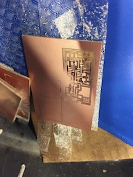
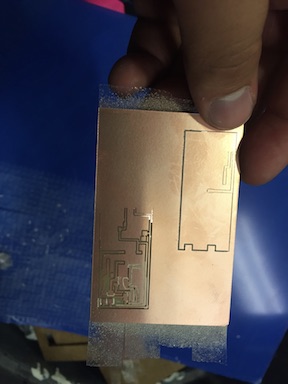
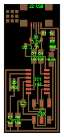
After this, once we had two "correctly" milled boards, we noticed that some of the traces were cut incorrectly. This led to a union of many traces that should not have touched.
"Correctly" milled board
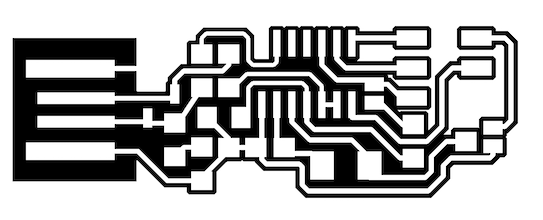
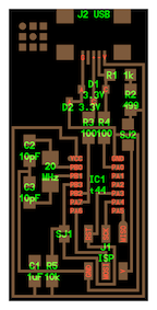
Design traces
As you can see in the previous picture, the traces that are near the edges, are not present in the board that was milled. This was a problem so this board design was scrapped. After this, I went with the hello.ISP design that is in the class page.
Hello ISP Board Soldering Experience
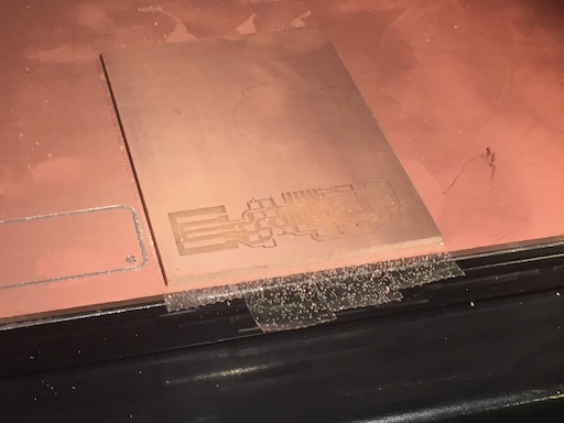
After downloading the hello.ISP design and configuring the mill, I tried to mill a new board. This new board milled fine, and I decided to do a backup board just in case. After the backup boardI made another backup board that used a different design which utilized a resonator instead of a crystal.
Design with crystal
Design with resonator
After milling the 3 boards, I went down to the electronics laboratory, with a solderer that I had, to solder the components unto the board. The first attempt at soldering was a total disaster. I tried to put solder on some of the plates for the USB connector, and ended up tearing out the traces from the board.
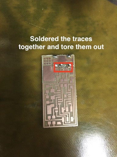
Soldering fail!
After this initial fail, I gradually got the hang of it and quickly soldered up the pieces in the board It took a while, but the best technique for soldering was to simply heat up both the edge of the component and the trace. Then you could apply the solder and it would flow from the soldering iron into the two heated places.
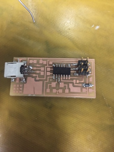
Initial soldering progress
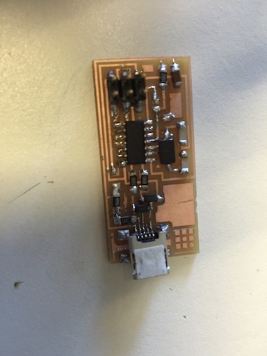
Final board 1 result
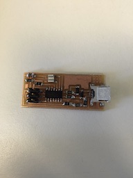
Final board 2 result
It's important to note that board 1 was the first board that I soldered. You can clearly see that board 2 is much better soldered. The only complicated component in board 2 was the resonator. To solder it, I put solder beneath the 3 lines and heated it up and gently placed the resonator.
Programming and debugging the board
Once the two boards were good to go, I proceeded to connect one into the lab machine and ran the commands to build and deploy the firmware. To facilitate my life, I wrote a script which simply ran the required commands. I was able to program successfully the board, however, when I tried to find it using the lsusb command, it would not appear. I checked the board and found that I had incorrectly put a 499K Ohm resistor instead of a 499 Ohm resistor. After switching them out, I was able to connect the board and find it with the lsusb command. I then proceeded to desolder the 0 Ohm resistors and use it to program the second board by changing the Makefile. This one worked flawlessly, and I was able to test that both boards worked as expected.
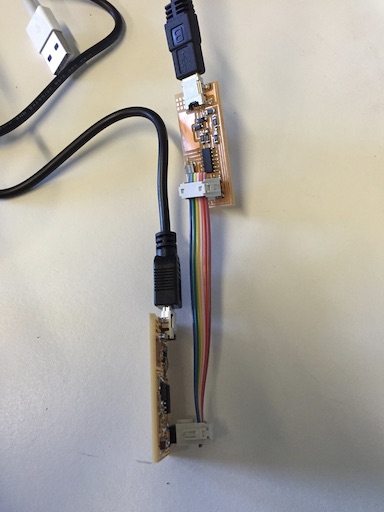
Connected boards with handmade cable