Week 5: Electronics Design
This week we had to redesign the barebones hello world fab board. We had to use a circuit design tool and the milling machine to produce the board and then solder it.
Schematic Design in Eagle
This week was mostly work in software. I started designing the fab board in Eagle. Eagle turned out to be similar to other Circuit desing software that I have used in the past such as Pspice. After reading a bit, I was able to figure out how to load the fab library into Eagle and start working in my schematic.
-
All that had to be done was the following (in Mac OS):
- Open Eagle
- Right click under Projects/eagle and select New/Schematic. This will open up the schematic window
- Click on the top bar and select Library>Use...
- Navigate to where you downloaded the fab library and make sure that its termination is .lbr
Once you had that, you could proceed to place components and join them using wires. The components could be found under the fab section. I used the components that terminated in fab.
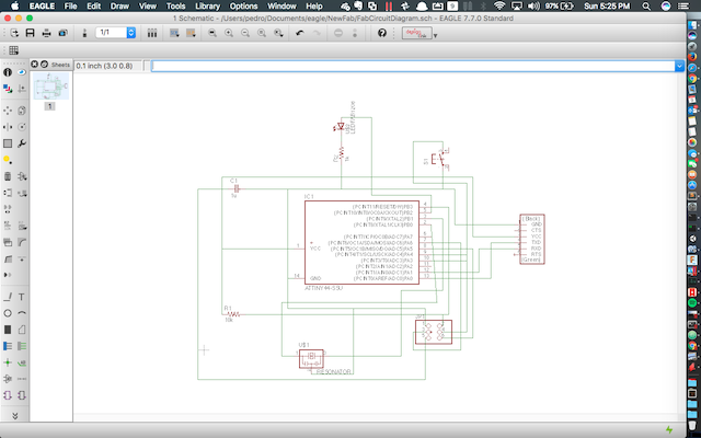
Initial schematic design
Board Design in Eagle
Now came the hard part: placing and routing components. Once the schematic was done, I generated the board design from the schematic using a button in the Eagle interface (Generate / Switch to board). I spent around 2 hours trying to place the components manually. I thought that placement might have been impossible and opted to move the button from inputs. Eventually I gave up and used the autorouter. I thought this was the end of my troubles... I thought wrong.
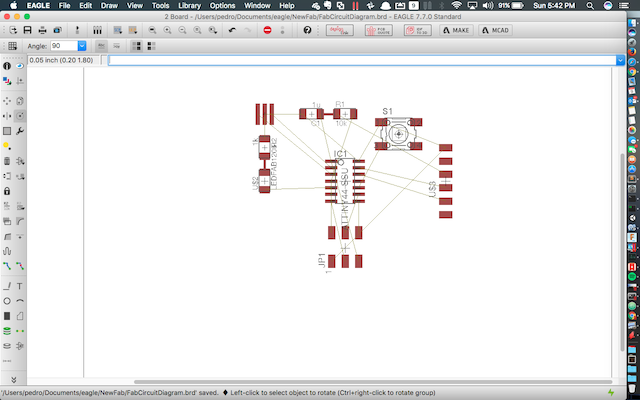
Original Button placement
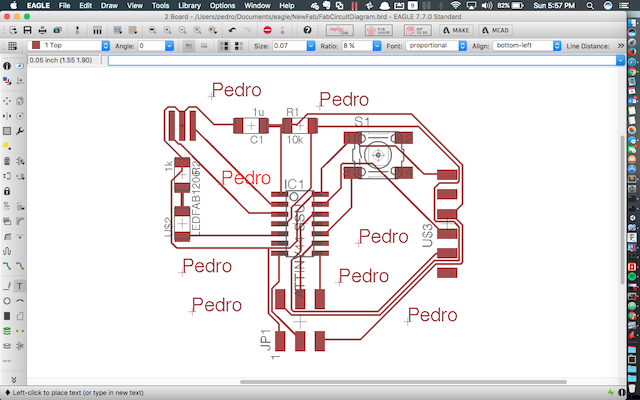
Final Button Placement and Autoroute result
Board Milling
I tried to mill this board, and quickly realized that there were problems. I tried redesigning the board, and eventually managed to produce one that kinda worked. I spent my monday afternoon and evening in the electronics lab with Anna and Mina. Here were the problems and some solutions.
- Traces were not detected - You might want to lower the size of the mill in the settings
- Traces were destroyed by the mill - You might want to increase the size of the traces or invert the colors or try to separate the traces more
- Board was too big in inches - try resizing the file into smaller dimensions
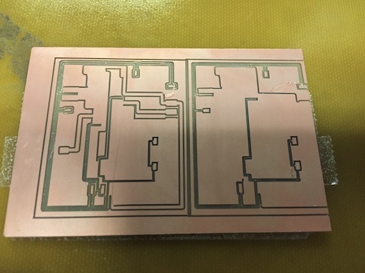
Here are some pictures of the process
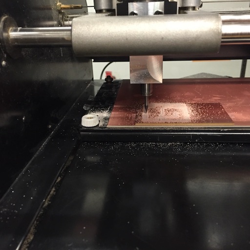
Board being milled
Failed Attempts
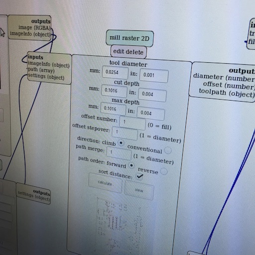
Adjusting the tool diameter
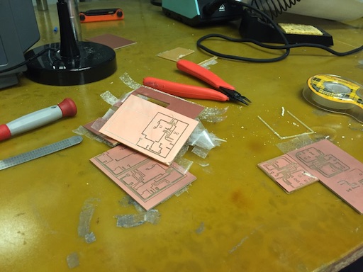
Graveyard
Board Soldering
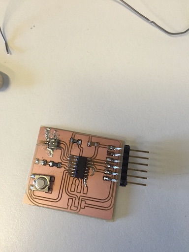
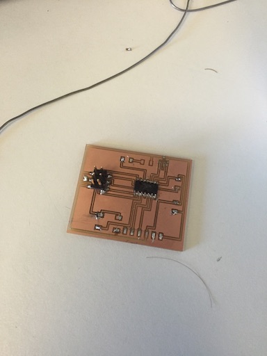
Finished Board
Once I had the board milled (albeit with tiny traces) I tried to solder the components unto it. Although I managed to solder them in, I connected the board and the computer shut down because of a short. I realized that the board might've been fried so I went to mill another one, but I found Anna who gave me one of her spares. I soldered the components unto the board and learned that to solder the microcontroller, it's easier to heat the solder from its pins and let it flow down into the contacts. I checked for shorts and found that I had one in the resonator and had to unsolder, remove some excess solder, and resolder the thing back in. Once I had this done, I proceeded to program the board to test that it was working.
Failed Board
Board Programming/Testing
Initially, I tried to connect both the programmer and the board, and found that the board was not identified. I simply decided to disconnect everything and reconnect, and that solved it. I was able to download the echo demo unto the board and test it in a Linux VM. There I saw that I was getting some garbage back instead of the echo and I realized that it was simply the FTDI headers were loose.
Files
Here are the files that I used for the models.