Week 9: Input Devices
This week we had to connect an input device unto our boards and read the values that came from it.
Testing the Programming
To test how to program the board, I decided to make the button and the LED that we had attached to our initial milling
work. To do this, I had to find out in the datasheet and in the design, to which pins I had connected the button
and the LED. After this, I searched online for some tutorials on how to program the board, and eventually found that,
since you have to program the board in C, you can use defines to create some shortcuts such as setting a port as
input or output, and setting a specific pin as input or output. I also found out that you can configure whether the pin is
pull up or pull down depending on the value of a register (PORTA = 0xFF; //signifies that it is pull up and
PORTA = 0x00; //would signify pull down).
This is important to know because the signal you're expecting could be of the same type and you'd never find it.
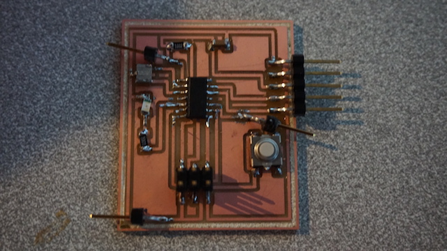
Milled Board
Analog Reading
Now that I had some idea of how to actually program the board by using inputs and outputs, I decided to try my luck with
the ADC. I found some tutorials online on how to configure the ADC correctly. You have to enable bits in a set of registers
in order to have the ADC work correctly and you be able to access it. Here you can see some of the configuration pieces:
// initialize adc
            // AREF = AVcc
            ADMUX = (1<< REFS0);


            // ADC Enable and prescaler of 128
            // 16000000/128 = 125000
            ADCSRA = (1<< ADEN)|(1<< ADPS2)|(1<< ADPS1)|(1<< ADPS0);


              //Select the channel
              ch &= 0b00000111;  // AND operation with 7
              ADMUX = (ADMUX & 0xF8)|ch;     // clears the bottom 3 bits before ORing


            // start single conversion
            ADCSRA |= (1<< ADSC);


            // wait for conversion to complete ADSC becomes '0' again

            while(ADCSRA & (1<< ADSC));
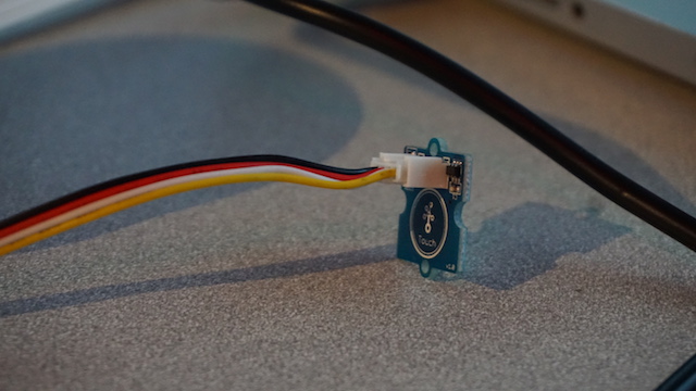
Touch Sensor
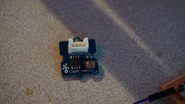
Light Sensor
Board Setup
To make it as easy as possible, I decided to solder 3 pins into the original board that we had milled, to be able to reuse the board and not have to mill another one. I connected the pins to cables, and then to a 4 cable connector that lets me access a Touch, Temperature, and Light sensor that I had. I set the code for it to read the value of the pin and turn an LED on if the values in the pin surpas a certain value (Hot temperature, Light present, Touch the touch sensor). This worked fine after I figured out that I was missing setting the LED pin as an output. Here is a video of the working system: Working system
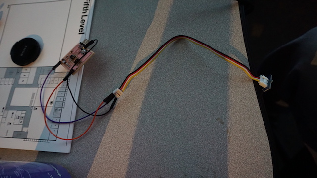
Board Setup
Files
Here are the files that I used for programming.