This week the assignment was to add an LED and a button to a generic board. I've done a bit of circuit design already I decided to work on a circuit for my final project.
Before arriving at MIT I worked with the Coded Structures Lab at the NASA Ames Research Center where I helped developed a robotic assembly system for the construction of digital cellular materials. As a progression of this project I have been helping with the development of a relative robot, capable of traversing through the structure whilst carrying out inspection of its condition. Whilst assembling these structures by hand, we realised that the vibrations were transmitted very differently through the structure when a broken or unattached voxel was present. Therefore, this week I've designed a circuit that I can use to experiment with different vibration sensors.

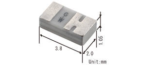
I settled on using a piezo electric transducer to convert mechanical vibration into an electrical signal which will be processed using the ATTiny 44. This week I worked with two types of piezo transducer; a Piezo Electric Disc and a surface mount Shock Sensor.
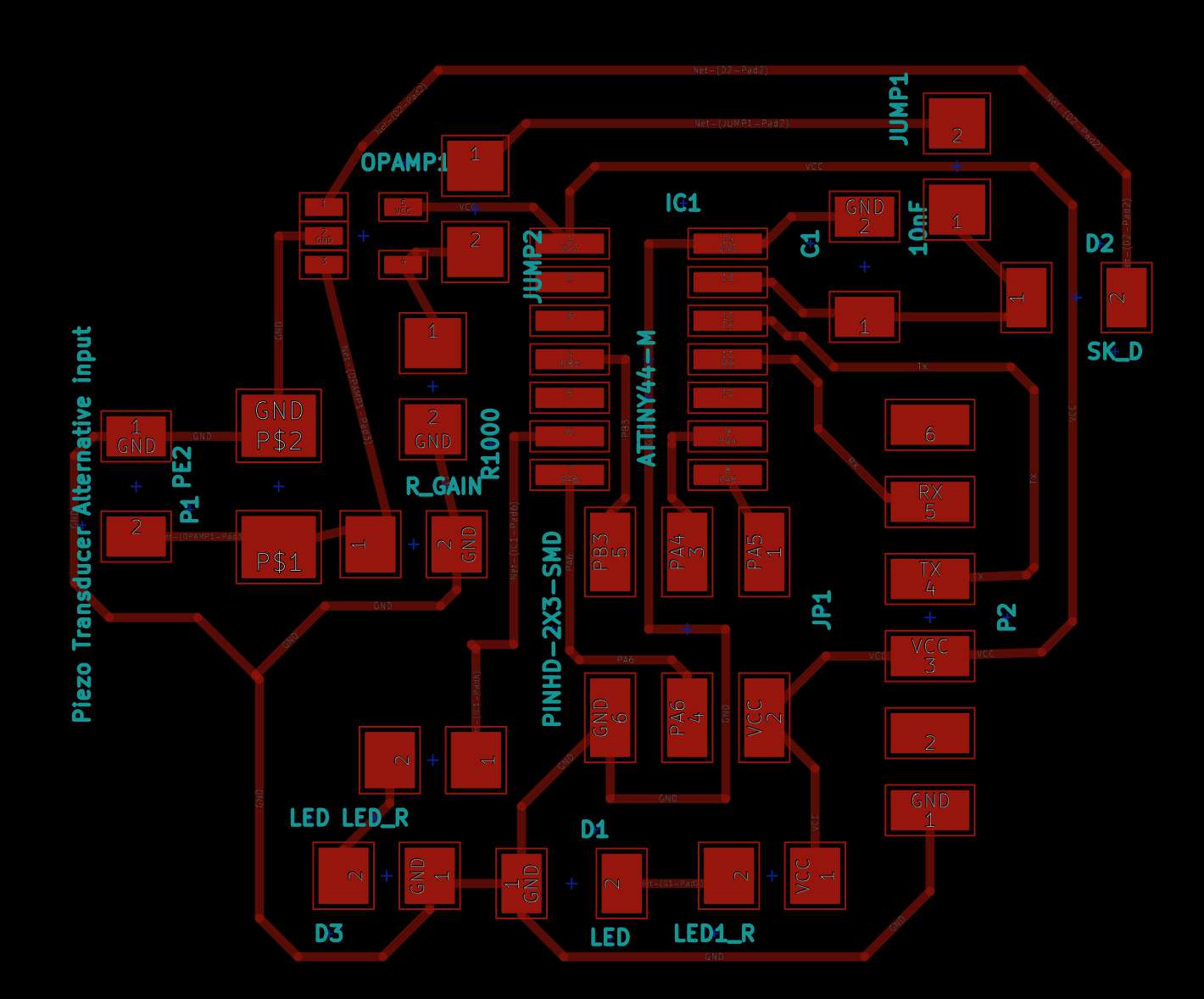
Eric gave me a lot of tips regarding different circuit types. Below is a diagram of my final circuit with descriptions of what each section does. This is still a work in progress.
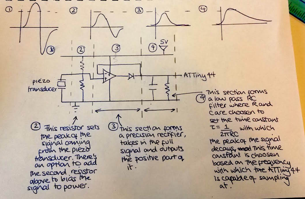
Circuit section 2 - I first experimented with the piezo transducers that I wanted to try out using an oscilloscope. The disc produced a peak voltage of around 10 V, thesurface mount device produced a peak of around 500 mV. In wanted to bring the output voltage of the disc piezo trasnducer into the range of 5V. The oscilloscope can be modelled as a 1M ohm resistance, therefore I chose to use a resistance of 1k ohm. Given the output peak of the surface mount signal is so small, I didn't include a resistor in this section.
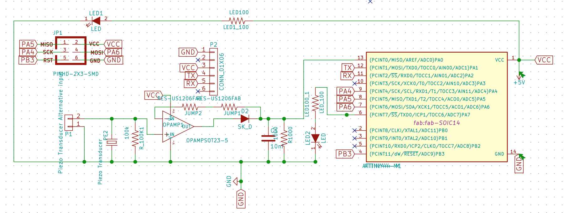
LED resistors - These are set according to the forward voltage of the LED, as specified in the datasheet. Assuming a required current of 20mA, I chose to use a 100 ohm resistor for both the LEDs. It was interesting to learn that the voltage drop across an LED normally rises as the light frequency increases, meaning that different coloured LEDs have different voltage drops.
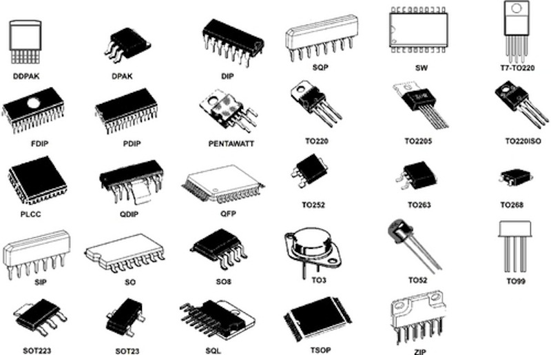
I'd previously used Eagle to design boards but thought I'd give KiCad a go. One good/bad thing about KiCad is that it separates the assignment of parts and footprints. This is bad when you're starting out as it adds another level of complexity to the design process and file management The fab.lib and fab.mod files were ported using an automated process directly from Eagle, as a result I found that pin assignments given in the schematic for the ATTiny44 didn't translate correctly into the footprint on the board. I overcame this by using the SOIC14 package that is included with KiCad as standard.
This was fairly straight forward once I had figured out how to install fab.lib and fab.mod. The Electric Rules Check function is helpful although it makes you add 'no connect' symbols on any pins that aren't being used.
I've yet to resolve one issue regarding the labelling of parts. When I first designed and netted the schematic, I hadn't given the components particularly descriptive names. After routing all my traces I went back to the schematic to change names and values of the components and reread the netlist, the program brought in a whole new set of parts. I think there's a way around this using a certain combination of checkboxes when reading the netlist but I haven't figured out quite what combination this is.
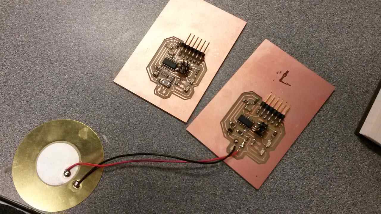
I fabricated two boards in order to test each type of sensor. Unfortunately during testing I ripped up the UART input pins by applying too much force, therefore, in the future I'm going to use through hole pins.
The following two videos show the signal generated with the sensors hooked straight up to the oscilloscope in comparison to the signal after being filtered by the circuit. The first video shows that the amplitude of the signal has reduced and chopped, however the output the low pass filter hasn't extended the peak correctly, therefore I'll need to go back and try out a different RC combination, probably using a higher capacitance.
For the second video I removed in the gain resistor. The signal comes out differently from this component. I'm keen to proceed with this one due to it's size however I'm going to need to iterate on the current circuit design to get a useful signal out.
I now have a much better idea about how to go about researching circuit types to sculpt signals. The first thing I need to do next is learn to program the ATTiny sense and analyse the signal. Secondly, I need to attach the sensor onto a voxel structure and iterate on contact methods and circuit design until I get out sufficiently different signals depending on whether a broken or unattached voxel is present or not.