There are a number of different companies that produce different microchips. These companies and startups have produced breakout boards for various micro controllers which make them easier to get going with.
| Company | Microcontrollers produced | Associated break out boards |
| Atmel | Atmel produces AVRs which form a family of microcontrollers including the tiny, mega and XMEGA. The AVR family use a modified Harvard architecture. ATTiny44 can be decoded as AT + Tiny + 44 = ATmel + Tiny family of chips + 44 model of Tiny. | Arduino |
| ARM | ARM microcontrollers are the most prevelant brand of chips to be found in mobile phones. Most of their processors fall into Cortex families including Cortex-A, Cortex-R and Cortex-M. Other companies license their design. | Raspberry Pi and STM32 Discovery |
| Microchip | Microchip produces a family of chips called PICs, they recently acquired Atmel. | Various boards available |
| STMElectronics | This company produces a couple of families of microcontrollers including STM8 and STM32 where the 8 and 32 refer to | STM32 Value line discovery |
| CPU Core | The CPU core ensures correct program execution, in order to do so it needs to access memories, perform calculations, control peripherals and handle interupts. The entire family of AVR chips use a Harvard architecture. The fast-access Register File contrains 32 x 8-bit general purpose working registers. One example of its use is when the The Arithmetic Logic Unity (ALU) takes takes two operands as an output from the Register File, executes an operation and sotres the result back in the Register File in one clock cycle. The number of bits a microprocessor is specified as being refers to the register width. Most of the boards we're using in this class are 32-bit. 64-bit microprocessors are often using in PCs. |
| Memories | AVR architecture has two main types of memory, data memory and program memory. The In-System Re-programmable Flash is program memory, SRAM is data memory and EEPROM is used for data memory. Different memory types can be volatile or non-volatile and have different levels of endurance. This particular family of chips has three variants, which include increasing amounts of each type of memory for increasing cost. It's the on chip ISP Flash that allows the chip to be re-programmed either using a conventional non-volatile memory programmer or by an on-chip boot code running on the AVR core. |
| Clock system | Different parts of the AVR architecture use different clock subsystems. The CPU clock is used by parts of the system concered with the operation of the AVR core. The I/O clock us used by I/O modules like timer/counter and the external interupt module. The Fhlas clock controls operation of the Flash interface. The ADC gets a dedicated clock domain in order to allow it to stop the CPU and I/O clocks to reduce noise. Clocks can be sourced from different places, either externally, an internal 8MHz oscillator, an internal low power 128kHz oscillator, a low frequency crystal oscillator. Also XTAL1 and XTAL2 can be configured for use as an on chip oscillator using either a quarz crystal or a ceramic resonator. You have to program the fuses depending on which clock type is used and the best type of clock to use depends on how the chip is being used. |
| Power management and sleep modes | These chips are good for low power applications. Sleep modes enable the application to shut down unused modules in the MCU to save more power. |
| System control and reset | During reset all I/O registers are set to their initial values and the program starts execuction from the Reset Vector. |
| Interrupts | Describes how interrupt handling is performed, including a list different program addresses that can be used for different types of interrupts. |
| I/O ports | All AVR ports can be used as general digital input and output ports. The pin drive when in output mode is strong enough to drive an LED. All port pins have individually selectable pull-up resistors with a supply voltage invariant resistance. Most port pins have alternative functions including ADC input channel, pin change interrupt, analog comparator, MOSI, MISO, timer/counter input capture pin. |
| 8 bit timer/counter0 with PWM | This module allows accurate program execution timing (event management) and wave generation. |
| 16 bit timer/counter1 | This module allows accurate program exectuion timing (event management), wave generation and signal timing management. |
| Timer/counter prescaler | A prescaler is an electronic counting circuit used to reduce a high frequency electrical signal to a lower frequency by integer division. |
| USI - Universal Serial Interface | This provides the basic hardware resources required for serial communication. AVRs include an 8-bit USI Data Register (USIDR) which contains incoming and outgoing data. You can use this interface in 3-wire or 2-wire modes. |
| Analog comparator | The analog comparator compares analog input pins on AIN0 and AIN1 and sets the Analog Comparator Output when AIN0 > AIN1. The comparator can be configured with a multiplexed input to allow multiple analog singles to distinguish between. |
| Analog to digital converter | The ADC is wired to a nine-channel analog multiplexer which allows it to measure the voltage at 8 single-ended input pins, or between 12 differential pairs of input pints, of from one internal, single-ended voltage channel from from the internal temperature sensor. |
| debugWIRE on-chip debug system | This system uses a One-wire, bi-directional interface to control the program flow, execute AVR instructions in the CPU and to program the different non-volatile memories. |
| Self-Programming the Flash | This is a mechanism provided to deonload and upload program code by the MCU itself. |
| Memory programming | Contains information on programming fuses, as well as how to program other memory types. |
| ELectrical characteristics | Provides details of the electrical limits in terms of voltages and currents that these chips can handle and should be operated at in different modes. The supply current in various modes is dependent on the magnitude of Vcc and frequency used. |
| Typical characteristics | Decribes the conditions you should aim to run the chips in. (Contains lots of graphs) |
| Register summary | List of registers and their associated addresses. |
| Instruction set summary | List of instructions including a description and how they can be operated, also includes the number of clock cycles an instruction takes. |
| Ordering information | Lists ordering codes, probably helpful for looking through Digikey. |
| Packaging information | Shows the dimensions of different packages available. |
Decided to figure out how to program the XMega, I just fabricated an unedited file from the class website.
Tried the steps below without installing Crosspack and AVRDude. Crosspack is a development environment for AVRs running on Mac OSx, download was straight forward. AVRDUDE is a program for downloading and uploading the on-chip memories of Atmel's AVR microcontrollers. It can program the Flash and EEPROM, and where supported by the serial programming protocol, it can program fuse and lock bits. I installed it using homebrew: brew install avrdude. However when I ran avrdude I got the following output:
dyld: Library not loaded: /usr/local/lib/libusb-1.0.0.dylib
Referenced from: /usr/local/opt/libusb-compat/lib/libusb-0.1.4.dylib
Reason: image not found
Trace/BPT trap: 5
Turns out that although I had the libusb package installed, it wasn't linked correctly, to overcome this I ran brew uninstall libusb and then brew install --overwrite libusb. Seemed to work OK after that.
Before programming my board, I fabricated a design from the website which includes an XMega 16E5, we didn't have any 16E5 but the 8E5 is the same thing but with less memory. I downloaded hello.ftdi.16E5.blink.c and hello.ftdi.16E5.blink.make (note that the make file doesn't have .c before make, it does for the 44 example and so you need to edit this when taking commands from the programming png). In those programs I edited all references to 16E5 to being 8E5.
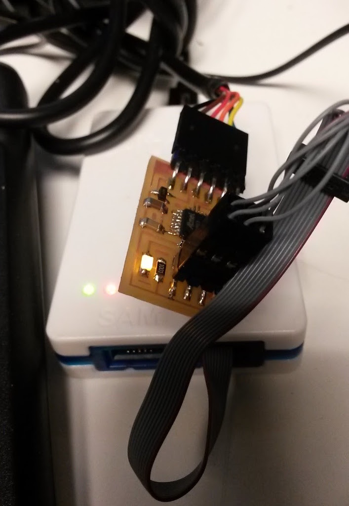
Initally I tried programming the board with my FabISP, however, the FabISP can only be used for ATTinys and Mega chips, therefore I had to use the Atmel ICE PDI. In addition, my Mac ran into issues making the files so I ran the following commands on a Linux computer. With a lot of help from Sam I figured out what the commands should be by looking at the examples on the programming png and adapting them to the file names I had downloaded and the functions included in the make file.
make -f hello.ftdi.8E5.blink.make
sudo make -f hello.ftdi.8E5.blink.make program
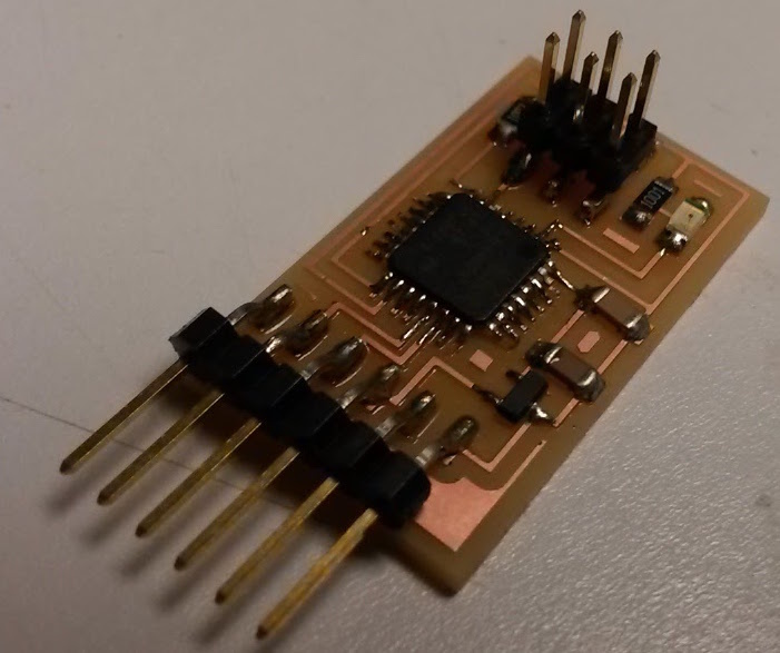
Couldn't get my board from week 3 to work so I decided to go back to the week 3 design task and make a basic one including the tag connect connecting method as recommended by both Sam and Eric. Using the data sheet helped me distinguish between the different types of ATTiny44A, in KiCAD the letters after 44A represent the package type, therefore, the correct part to choose is the ATTiny44A-SSU.
Reminded of KiCAD tricks - when you import your netlist into PCBNEW and all the footprints are stacked on top of each other, click on the Mode icon (right had side of horizontal toolbar), then right-click away from the stack of footprints and select option to spread them out. (Image of the mode icon opposite).
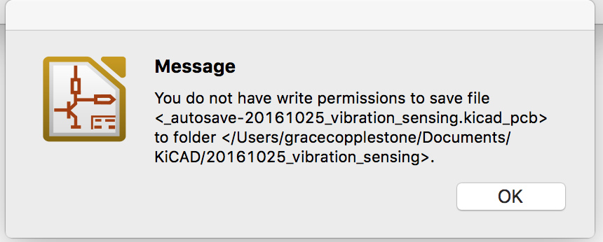
I managed to get pretty far along with design this board however KiCAD suddenly informed me that I didn't have the write permissions of save my files into the location I'd previously been using, so when I closed out the window I lost my work. Kind of frustrating and I think that's the final straw for using KiCAD in the future, still too many bugs to get a decent workflow going. Going to try out Matt Keeter's programming based board design tool and see how far I get with that.
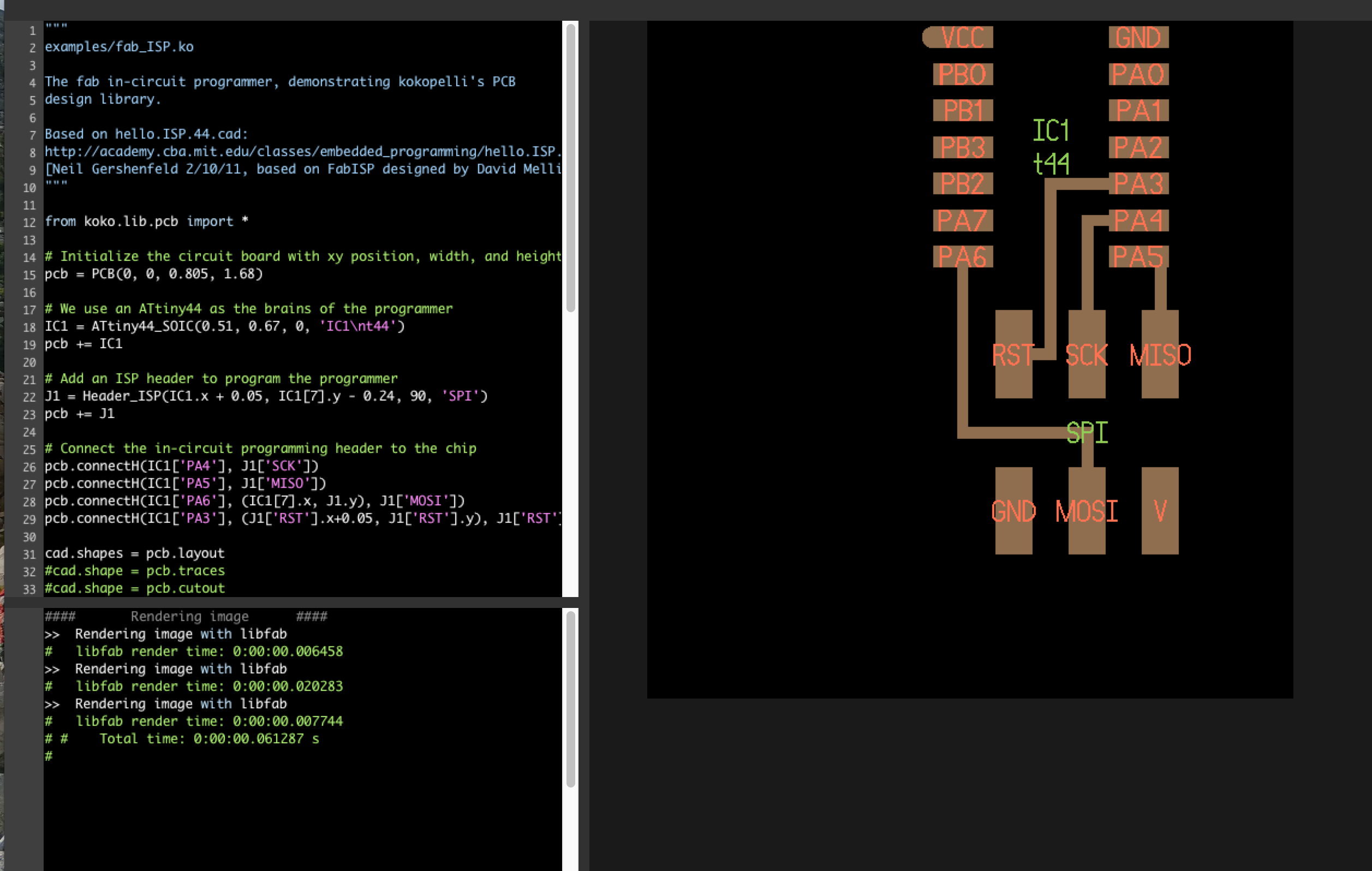
So far so good with Matt Keeter's tool.
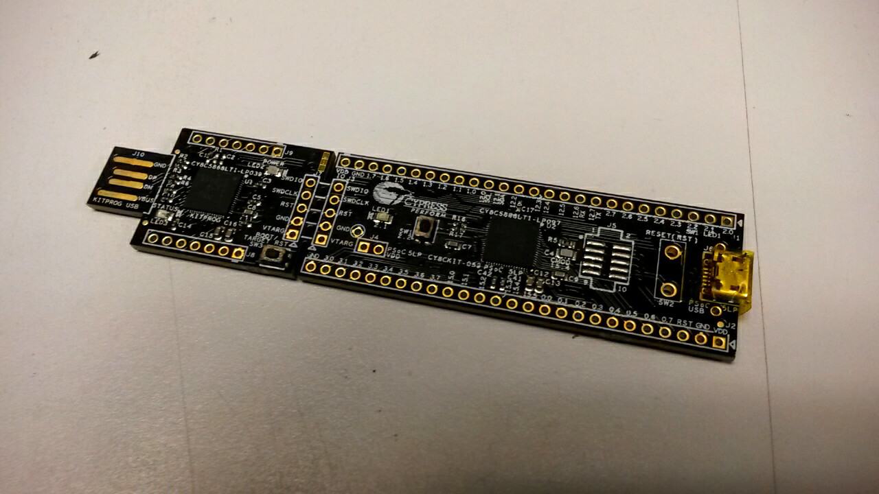
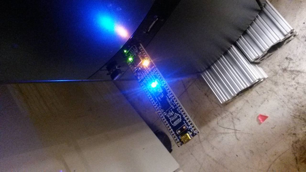
I had to use Windows for all of this, I downloaded and installed PSoC Creator from the Cypress website. The board comes as a single piece that can be broken into two parts, the KitProg board and the PSoc 5LP. This is the same idea as having the FABISP connected to a board that you've designed in order to program it and then breaking off the FABISP section. Lots of information here. I downloaded and installed the CY8CKIT-059 PSoC 5LP Prototyping Kit setup file and managed to run the example blinking light program. Discussed the PSoC with Sam, apparently there are several analog 'blocks' that can be implemented fairly easily such as a quadrature decoder. This block in particular is useful when you want to keep track of an encoder on a motor but not have to continually interupt the CPU to process values.