Half of this week's work was done at CBA and the other half was done at RepRap in the UK. I'd like to thank Adrian Bower for letting me come and use the facilities at RepRap and giving me lots of advice about circuit design and prototyping.
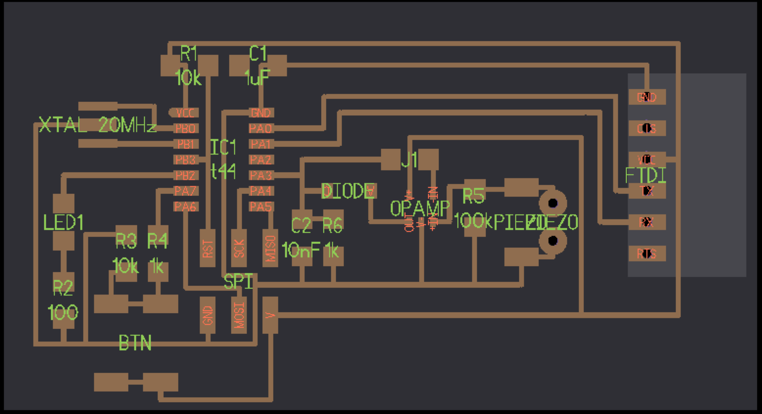
I remade the vibration sensing board from one of the first weeks of the class using Kokopelli. The software is perfect for Fab Class boards, it was particularly easy to add drill holes for the FTDI connection which I'd struggled to add quickly using Eagle and KiCAD. One initial mistake arose after I hadn't correctly formatted the shapes to be output as the cutout png file. I overcame this by using the following lines to generate the pngs for the mill, which were commented out depending on which output I wanted.
cad.shapes = pcb.layout
cad.shape = pcb.traces+(pcb.cutout-pcb.cutout)
cad.shape = pcb.cutout+(pcb.traces-pcb.traces)
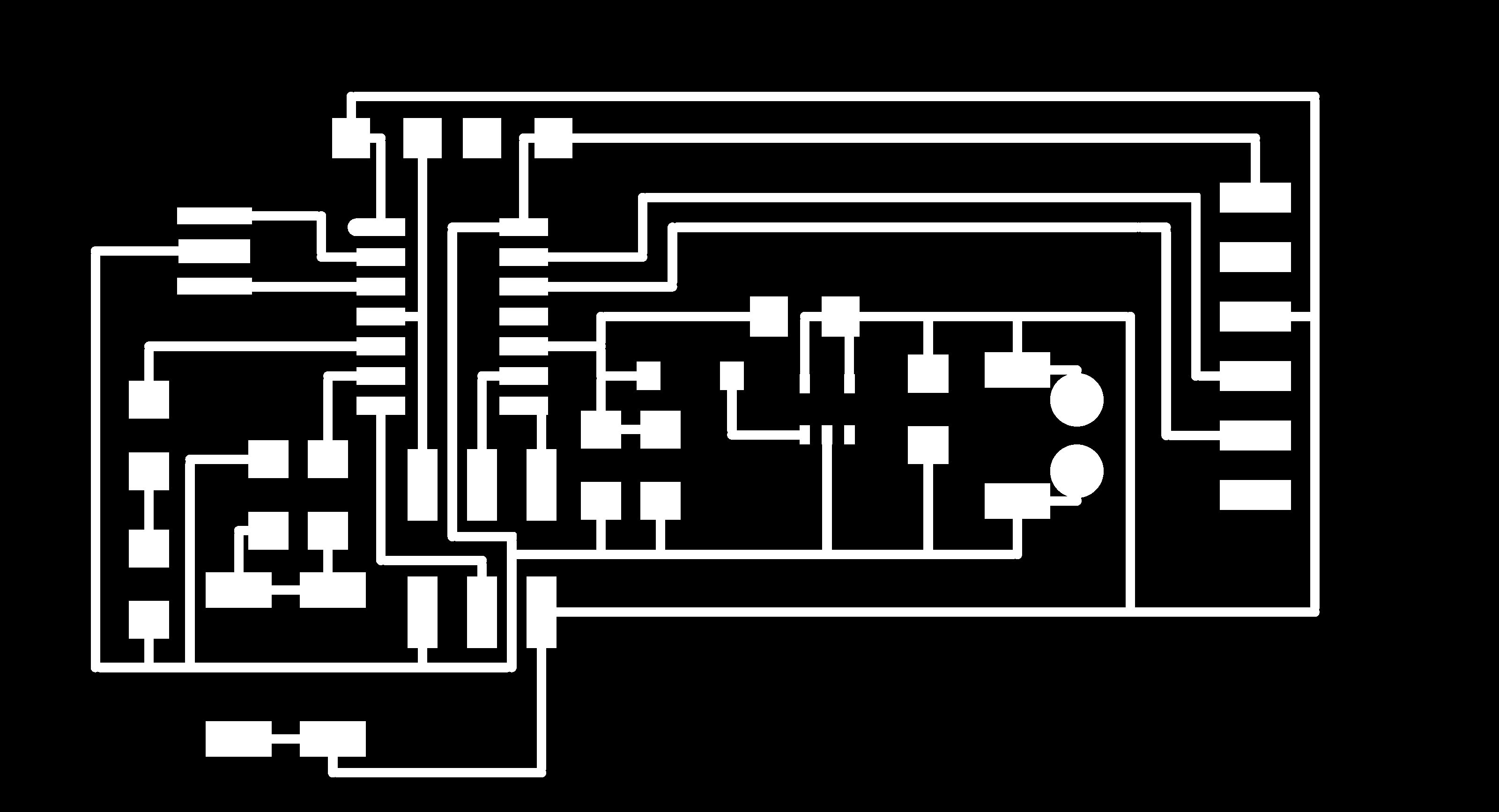
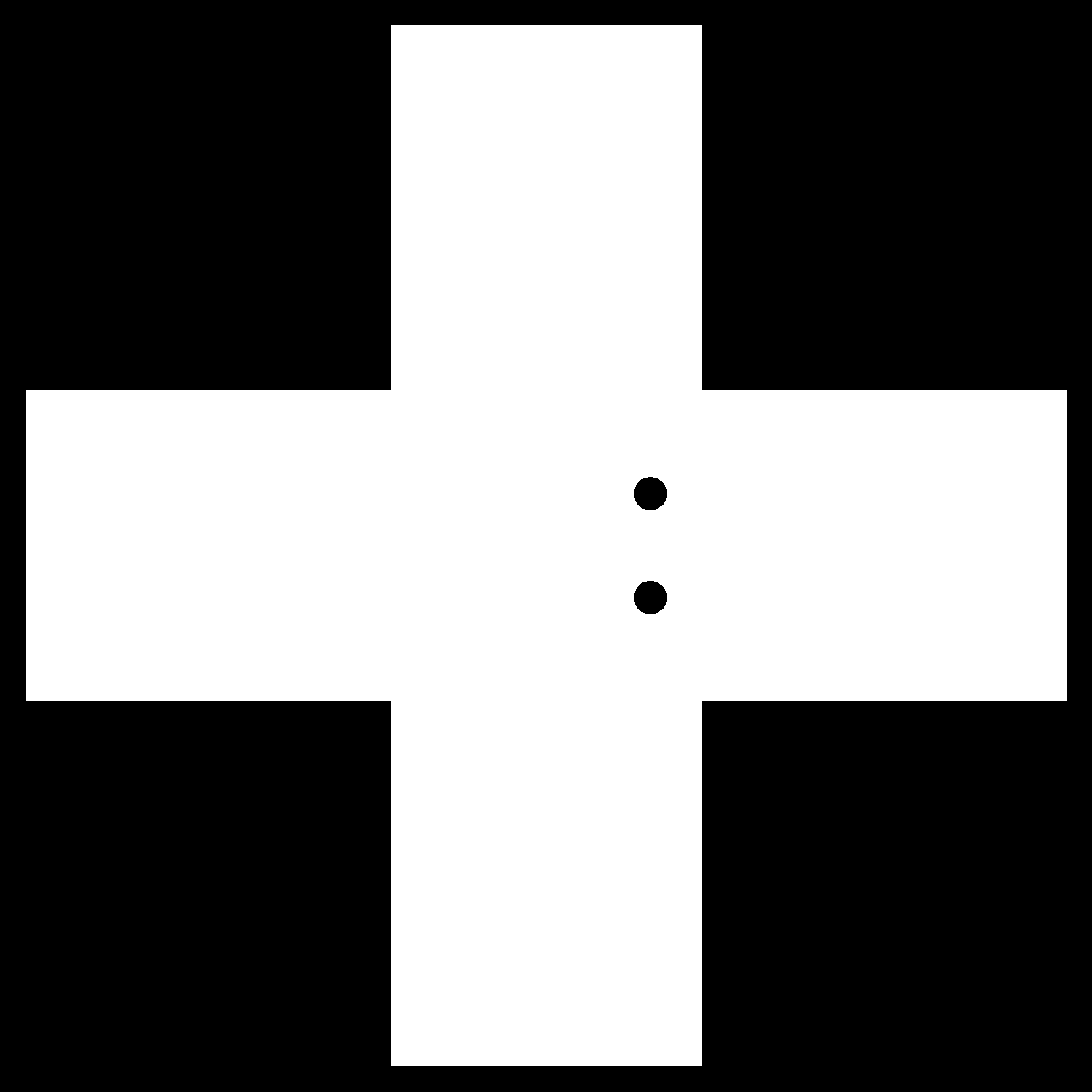
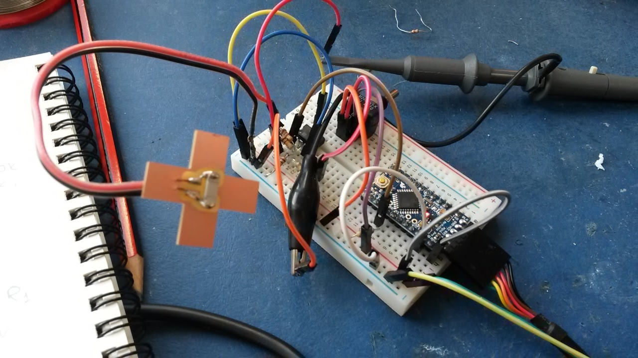
I then create a secondary board to carry the sensor. Again, Kokopelli was quick to use in terms of creating a custom cutout shape, I chose to use a cross to fit inside a voxel.

I stuffed the board and tested it. Initally, because I had used a two sided piece of copper, the FTDI connectors which went into the drill holes shorted on the other side. I overcame this by using a drill to remove the copper that immediately surrounds the holes of the back side of the board. It turned out that I had forgotten to reroute one trace when moving components which meant that the opamp was not being powered correctly. At this point I decided to prototype with a bread board and Arduino. This proved to be very helpful in to figure out resistor configurations and values without having to mill a new board each time.
This is the input data from the piezo shock sensor. It is displayed using the Serial Plotter function available within the Arduino IDE. I removed all delays from the Arduino program meaning that the device is measuring the signal at 20MHz. Next I will mount the sensor within the voxel structure and collect vibration data whilst tapping a complete and incomplete/broken structure.
Next I installed the sensor on a voxel structure and collected signals when the structure was fully assembled and when there was either a broken voxel present or one of the voxels was not fully connected. I analysed these signals using a Fast Fourier Transform.....