From computer-controlled cutting and modling and casting to embedded programming and networking and communications, this project will put many of the skills learned during the semester to practice.
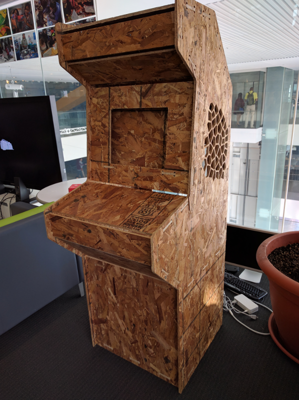
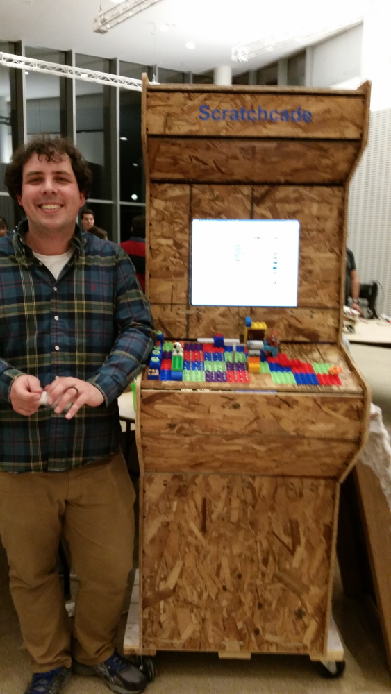
For my Week 6 assignment I worked together with my colleague Stefania Druga to build a press-fit game arcade cabinet with OSB. The project came together very nicely and even though I like the industrial style of the OSB I plan on using nicer quality wood for my final project.
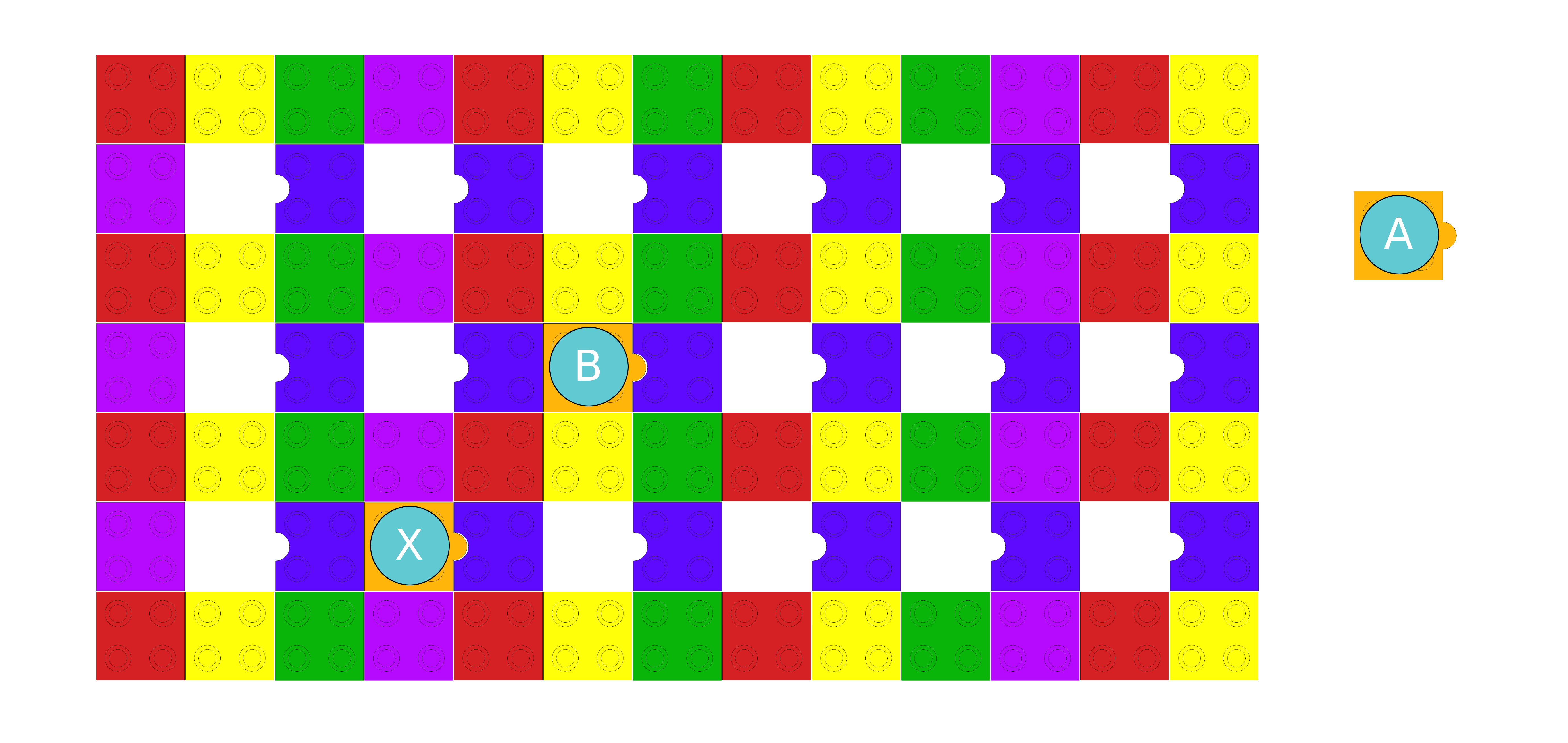
In keeping with the spirit of the LLK, I decided to try to make my control panel compatible with LEGO bricks. Since traditional LEGO bricks are a little too small I decided to model it around the LEGO Duplo set. Fortunately, Duplo bricks are also compatable with regular LEGO bricks!
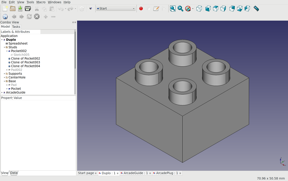
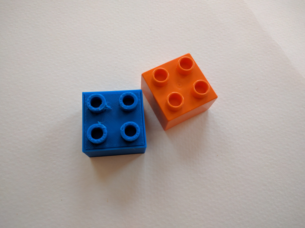
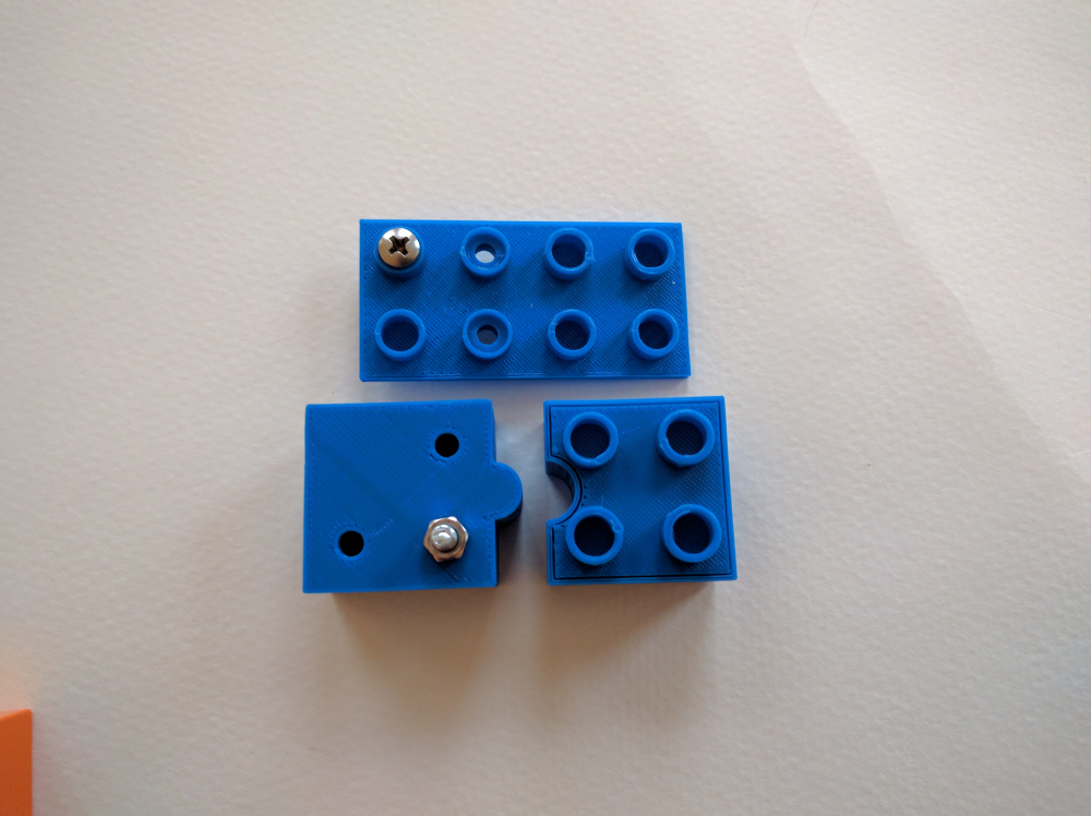
The first step was to create an accurate model of a 2x2 LEGO Duplo brick. Since I wasn't able to find documentation on the size of the brick I had to rely on a caliper and a little trial and error.
Now I started to think through how the electrical connections would work between the lego bricks. As a prototype I used machine screws embedded into the brick studs as the electrical connectors.
Week 13, networking and communications was a very productive week for my final project. Getting each button talking to my main controller board was one of the major challenges in my project. During the weekly assignment, I got everything working using serial drop communication, however, I will still need my controller board to use a USB hardware chip to appear as a USB HID device when connected to the computer. This way, the controller board will be able to relay the keyboard pressed in repsonse to the button states.
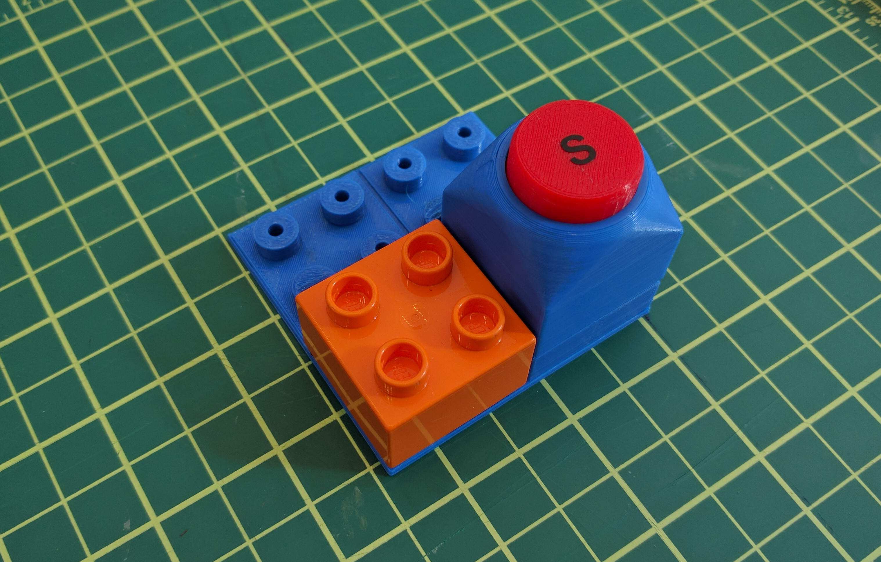
Now that I have all this working the final step is nailing down the form factor for everything. I used the Ultimaker 2 to start creating the enclosures around the button duplo blocks.
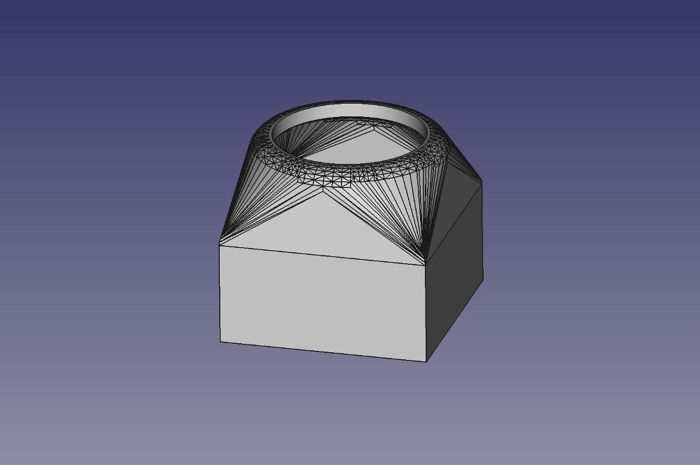
Throughout the semester I have become very comfortable using FreeCAD as my modeling software. It has some bugs/limitations, but it is extremely powerful and flexible.
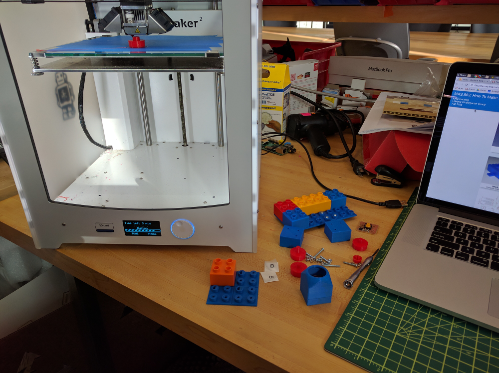
Using an Ultimaker 2 to print my button housings duing one of the few times it was working properly.
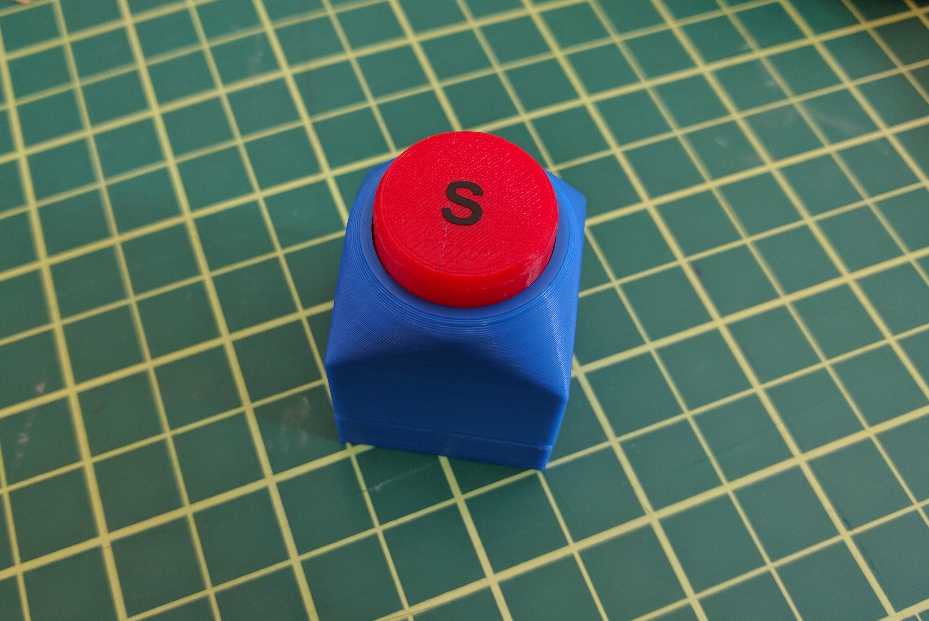
Fully assembled button
Earlier, I was using two screw heads that would press together to create the electrical connection between the button and the controller board. This was just a temporary solution and proved to be extremely unstable.
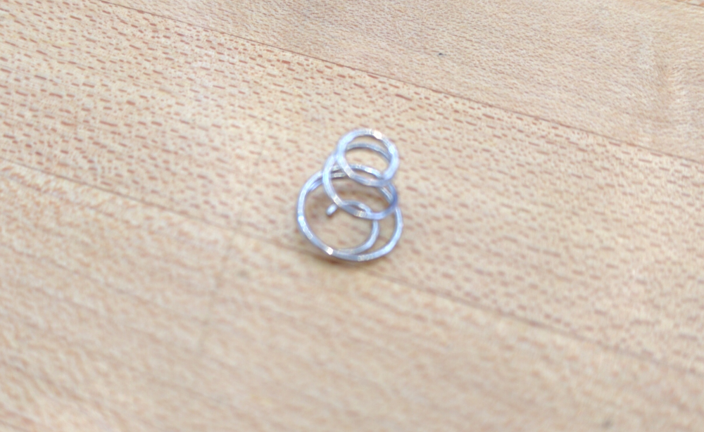
Next I tried Keystone 211 battery terminal springs. I quickly realized that this wouldn't because the springs would resist the button from being snapped into the plate. Also, each spring is slightly different height so unless it was a tight press fit there would be no way to guaruntee a good connection.
Finally, I landed on button snaps as the connector. Yes, that's right, button snaps. The kind you have on your winter coat. The button snaps have a predictable height and I found one with a perfect diameter to fit inside of the lego stud connectors.
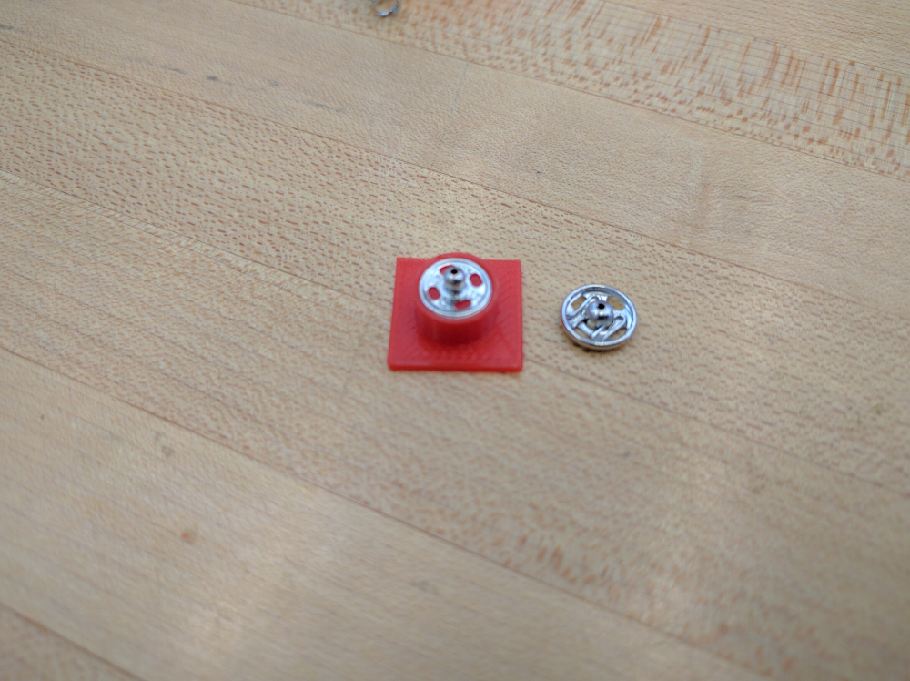
I ended up going with button snaps as my final connector. I am still in search of a better performing, low-cost, connector, but this will have to do for now.
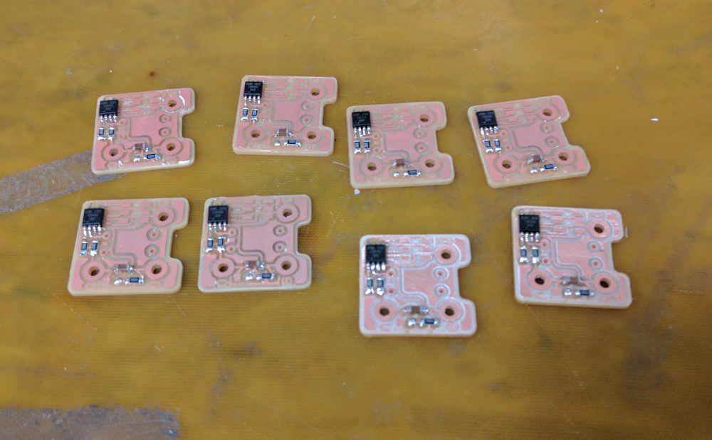
Once I had the button circuit finalized, I had to mill and stuff several of the boards.
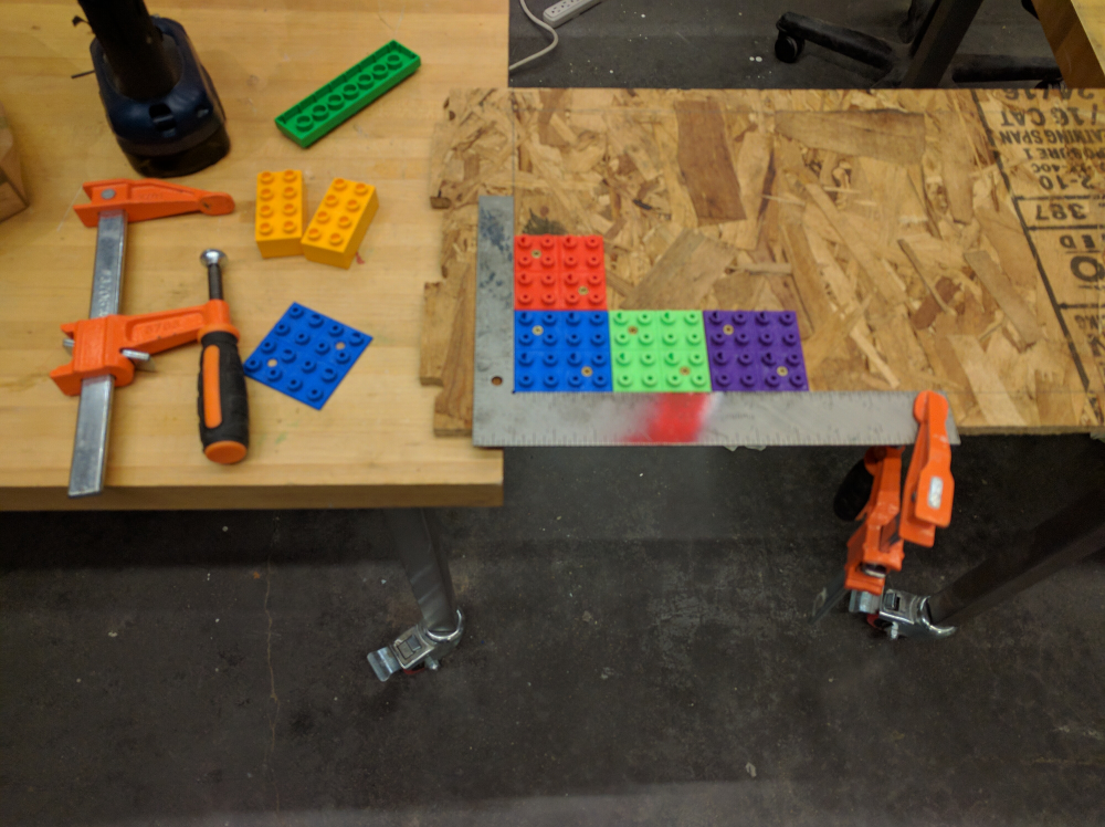
The base plates were also designed in FreeCAD and 3D printed. I chose to print them in four different colors (red, blue, green, and purple) to give the cabinate a playful look. I used a square ruler to make sure the plates were mouted straight and store bought duplo blocks to make sure they were lined up properly when drilling pilot holes and screwing them in.
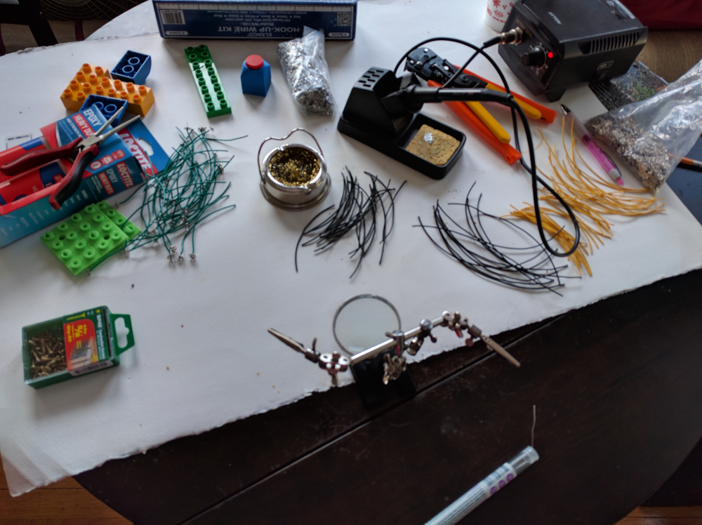
Now I had to solder all of the button snaps to go onto the mounting plates. About 1/3rd of the panel resulted in 96 soldered button snaps!
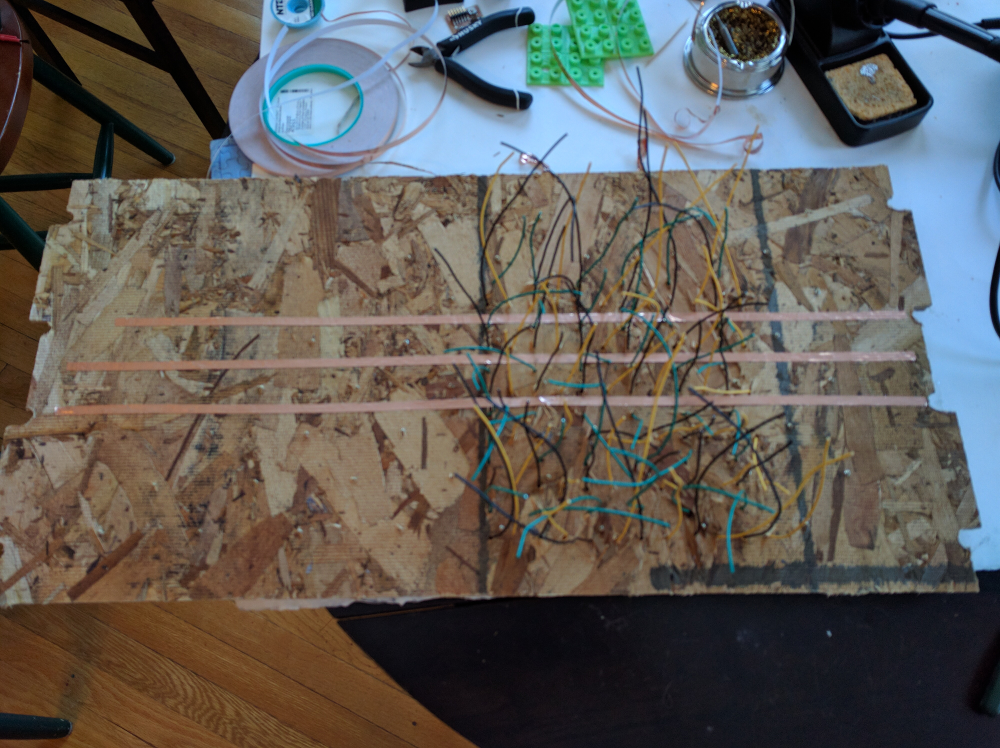
All of those wires! I layed down copper tape as the three buses that would carry VCC, ground, and data.
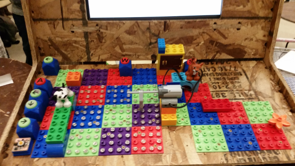
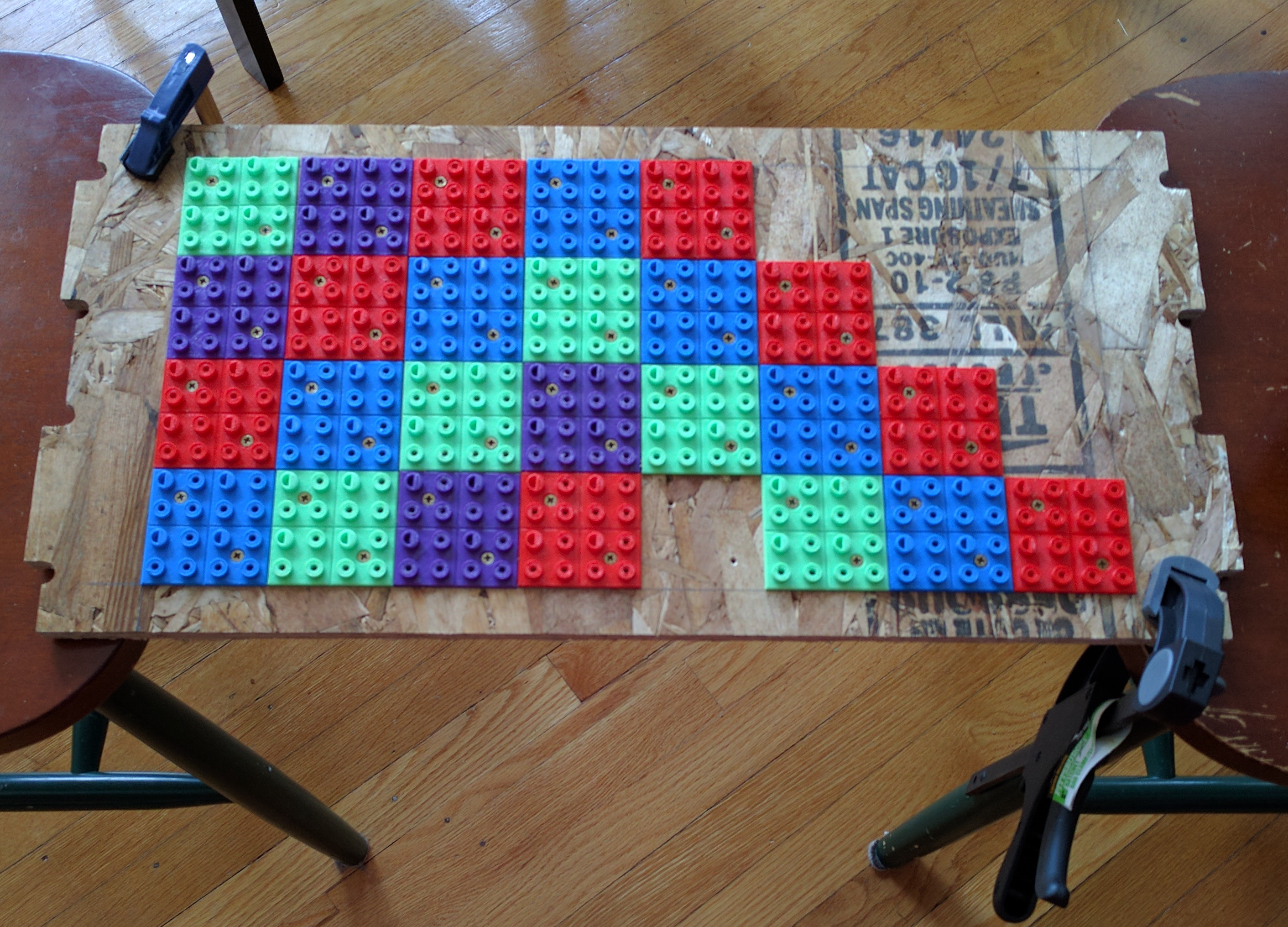
Once everything was soldered up, I installed the panel back into the press-fit cabinet and plugged in a few buttons and Duplo pieces.
Software and design files
ArcadePlate.fcstd - FreeCAD file for mounting plateButtonBody.fcstd - FreeCAD file for button housing
ButtonSleeve.fcstd - FreeCAD file for top part of button housing
Button.fcstd - FreeCAD file for button
Button.sch - Eagle file for button schematic
Button.brd - Eagle file for button board layout
btn-firmware.zip - Firmware for button written in C
Materials Used
- The cabinet was made out of the OSB wood that we used during computer controlled cutting week on the ShopBot in the CBA lab.
- 3D printing filament was sourced from Mircocenter on Memorial Drive. $14.99 each roll
- The button snaps were found in the LLK space
- The electronics used were all sourced from the CBA electronics shop. Each button contains a attiny44, two 10K resistors, one 1K resistor, a green LED, a 6 pin ISP header, and 12mm momentary switch, and a 1uF non-polarized capacitor.