For this week in HTMaA we were asked to add an output device to a microcontroller that we designed early in the course. Since most of my designs centered around the ATTiny45 chip, I decided to try to recreate the bipolar stepper motor driver using the ATTiny45. Since only four digital output pins are needed to drive the h-bridge chips, the ATTiny45 should be sufficient.
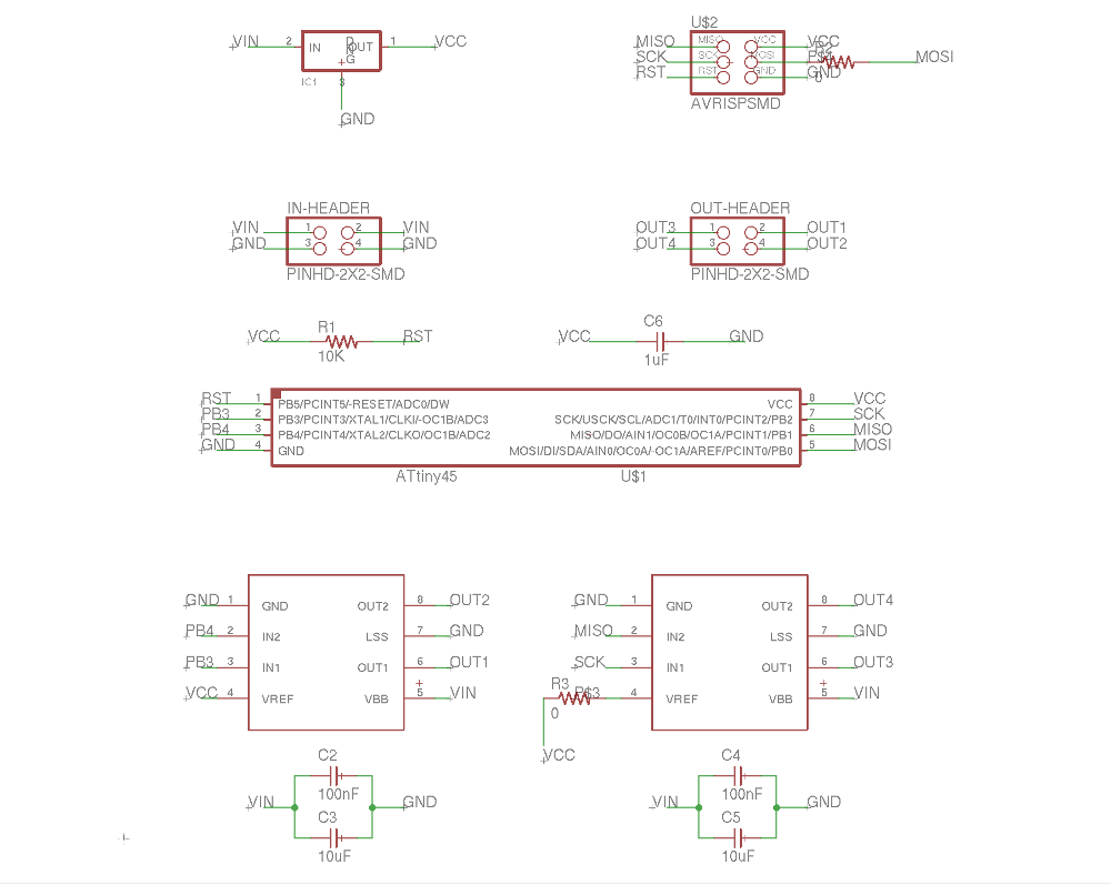
I created a simple schematic in eagle usign the ATTiny45 chip and two A4952 H-bridge motor drivers.
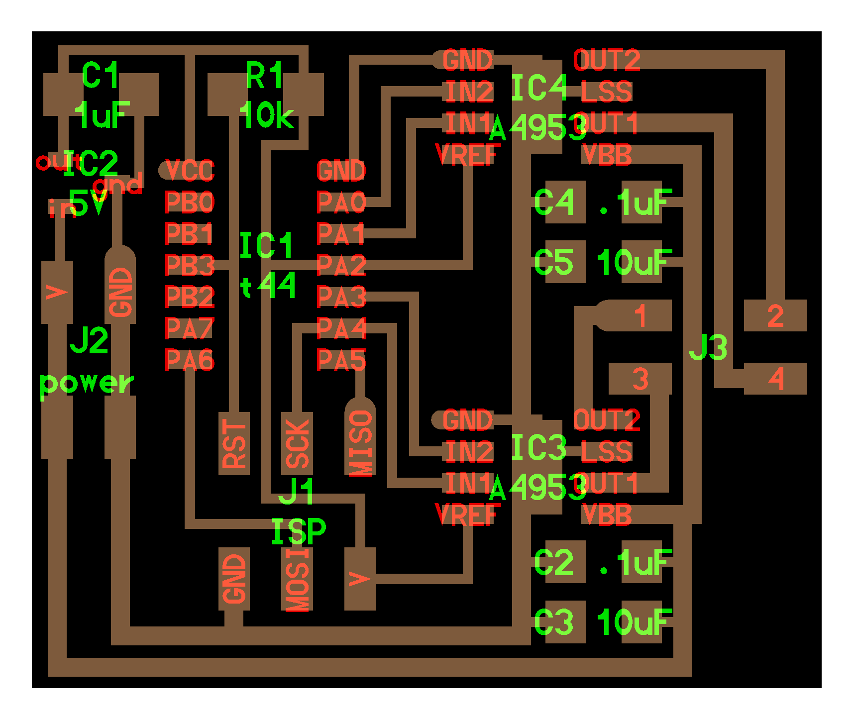
Next I tried to complete the board layout, using the hello.stepper.bipolar.44 as a guide. The power lines running around the outside use a .024" trace width to accomodate the higher current.
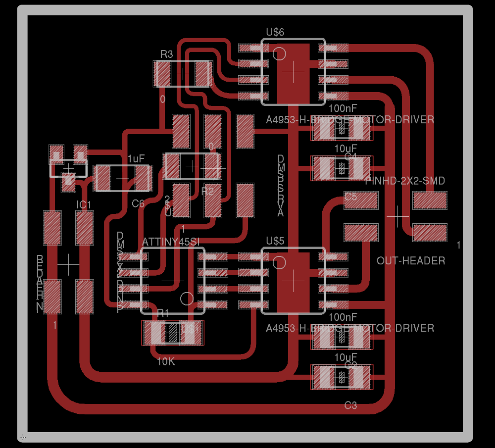
Unfortunately, when I imported the board design into the fab modules and tried to calculate the paths I realized that some of my traces were too close together.
I ran out of time to redesign my board so to make sure that I had something up and running before class I milled and stuffed the hello.stepper.bipolar.44 board.
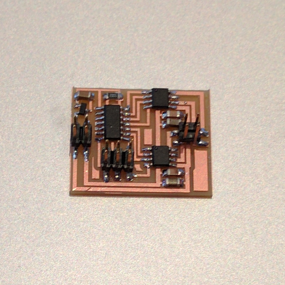
After uploading the code using a USBTiny programmer and applying 12V, the stepper motor started moving as expected.