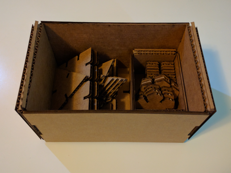
This week in HTM(a)A we explored computer-controlled cutting. Our assignment was to design and construct a press-fit construction kit out of corrugated cardboard. To accomplish this task, we had to explore an array of different 2D and 3D design software. I decided to use OpenSCAD for the construction of my kit since it makes it easy to parameterize the design.
I began by trying to create a press-fit cutout with a simple shape, a square. It took a bit of iteration to get a cutout size that was solid enough to hold the parts tightly while still allowing for easy disassembly.
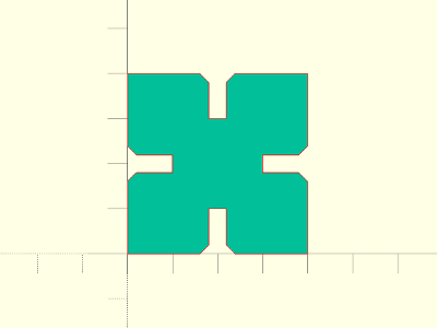
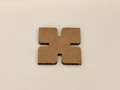
Once I was happy with the fit of the press-fit cutouts I moved on to creating more interesting shapes. Instead of drawing each shape and figuring out the rotation of the cutout manually, I decided to create an OpenSCAD module that would generate the shapes for me. I created an OpenSCAD library called "kit_parts.scad" that provided two modules, kit_connector and kit_plate.
kit_connector(r, h, c, k, n);
h - The thickness of the material being cut
c - How much to chamfer the cutouts
k - The kerf of the laser
n - The number of sides the polygon should have
kit_plate(d, xn, yn, c, k);
xn - The number of cutouts along the x-axis
yn - The number of cutouts along the y-axis
c - How much to chamfer the cutouts
k - The kerf of the laser
With these modules it was easy to generate an array of different connectors and plates.

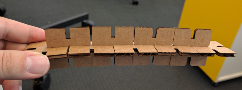
I was happy with the way the pieces fit together, but I wanted to see if I could improve the way they interlock. I modified the original design to a cutout that would grab onto the other object inspired by the designs that we were shown in class.

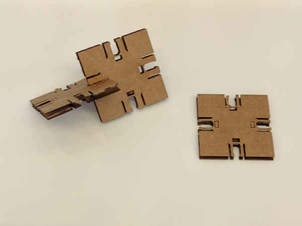
The new connector certainly worked. It was difficult to separate the pieces without destroying the cardboard. However, with this new connector the pieces did not fit as snuggly as they did with the basic slot cutout. I will need to modify the design to try to combine the best of both worlds.
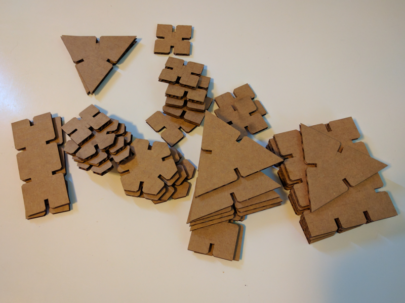
Now that I had so many cardboard parts I needed somewhere to put them. This inspired me to try to build an OpenSCAD module that would generate a foldable box simply by specifying the desired dimensions. Unfortunately, OpenSCAD didn't seem to be the best tool for this since polygons automatically merge together while rendering. This means that if I want to make partial lines where the folds would happen I would have to draw them in later in Corel. I really wanted the script to generate a final model that could just be sent to the laser cutter. Luckily I found a Python module called dxfwrite that allowed me to do just that! I created a simple python script, box-gen.py, that inputs the dimensions and thickness of material and generates a .dxf file that is ready to be loaded into the laser cutter.
usage: box-gen.py [-h] [--lid LID] l w h t o

Generate foldable boxes. Exports in .dxf format

positional arguments:
  l           inner length of box
  w           inner width of box
  h           inner height of box
  t           thickness of material
  o           output .dxf file

optional arguments:
  -h, --help  show this help message and exit
  --lid LID   generate a lid
One issue I ran into was that I couldn't export lines with a black color or at least the black lines wouldn't import into Rhino. To get around this, the script exports the lines for cutting in green and the lines for folding are red. This way you can specify a different cutting speed and power for each color.
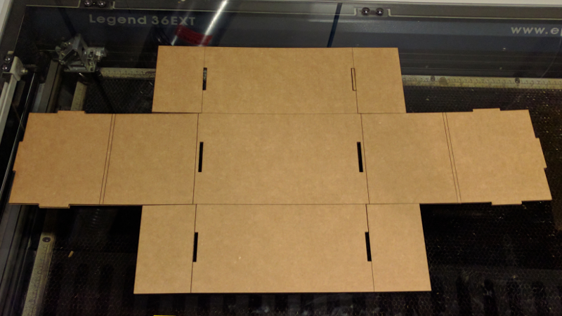
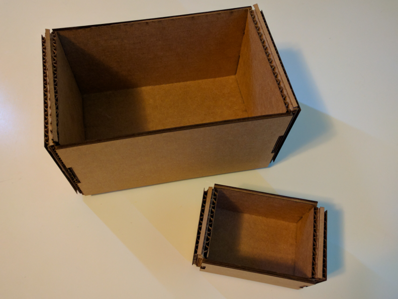
Next I plan on adding a boolean argument to box-gen.py to generate a folding lid and possibly the option to automatically generate column and row dividers.
