This week in HTMaA we were asked to make something big. In anticipation of a possible final project idea, my colleague, Stefania Druga and I decided to build a press-fit arcade game cabinet. Our goal was to build a fullsize arcade game cabinet build out of the terrible matrial that is oriented strand board (OSB).
Inspired by Neil's in-class demonstration and my natural affinity for FOSS software, I decided to try to create the cabinet design using FreeCAD. In the past I have always preferred OpenSCAD for 3D modeling, however, assembly of many components can be time consuming. Seeing that I could parameterize, design, and assemble my model in FreeCAD was enough to make me take a second look.
These were by far the two most useful videos to help get me started using FreeCAD:This video how primitives provided a nice overview of some FreeCAD basics as well as a look at what the design workflow might look like.
https://www.youtube.com/watch?v=xs1mFiJBYIo
This video from Youtube author Learn FreeCAD was great for getting an idea of how I could design and assemble something with many parts.
https://www.youtube.com/watch?v=08aFSivE3L8
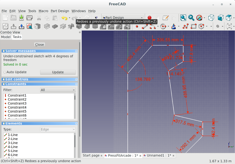
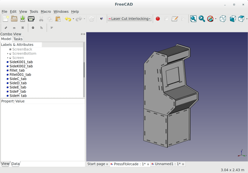
Once I felt comfortable with the basics of FreeCAD I set out to determine the dimensions of the cabinet. After a bit of searching, I came up with a general design based on some popular MAME cabinets. I designed the side panels using the polyline tool in the Part Designer workbench in FreeCAD.
Once I was happy with the side panel design and the dimensions were all constrained using the Spreadsheet workbench, it was time to start creating all of the panels that would connect the two large side pieces. I quickly realized that angled cuts would make the OSB wood crumble, so instead of each panel touching flushly at every angle I create a slight gap.
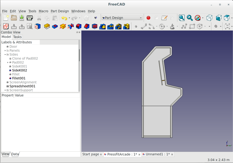
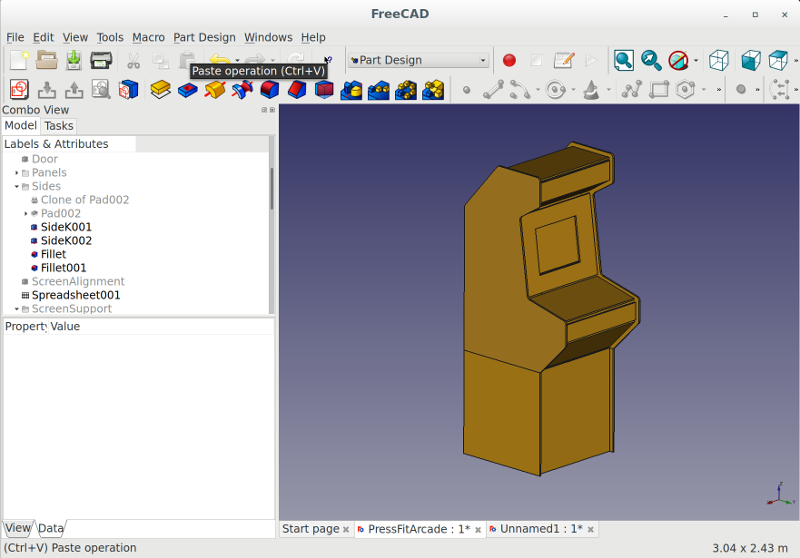
I used the Draft workbench to get all of the parts assembled correctly.
Fortunately for us someone had created a FreeCAD workbench for creating laser cut interlocks. The workflow of the workbench was a little strange, but the results were great! The Laser Cut Interlocking workbench even provides an option to layout the parts for a laser cutter/cnc machine.
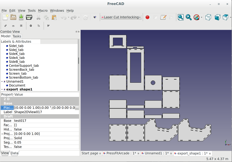
One issue with this Laser Cut Interlocking workbench is that it generates extra lines that separate the tabs from the main part. If the design was sent to the ShopBot like this the tabs would be cut off of the object. To fix this, I exported a flattened SVG from FreeCAD and removed the extra lines using Inkscape. From Inkscape I was able to export a DXF file to use with VCarve.
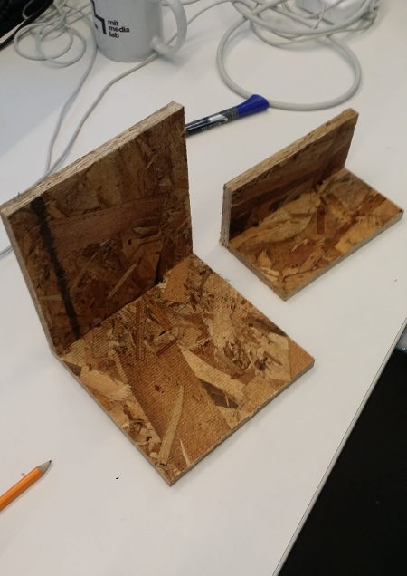
Before sending the design to the ShopBot we decided to test out the pressfit. With the kerf tolerence set to 0, the parts came together nicely. Since the thickness of the OSB material varies, we decided cut it out and use a hammer and file later if necessary.
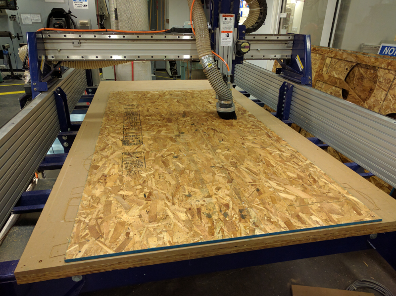
We ran into some crashing trying to use the ShopBot software, but we quickly learned what sort of actions the machine didn't like. It's best pratice to close the control window when switching back to the console window. We also learned to try to minimize the amount of movements while homing the X and Y axis. We used T-bone fillets on any part that required a square hole for press fitting. Our design was so big that we needed three sheets of OSB to cut it all out. Fortunately, many students purchased their own wood or didn't use all of their alloted stock so there was plenty left over for us to use.
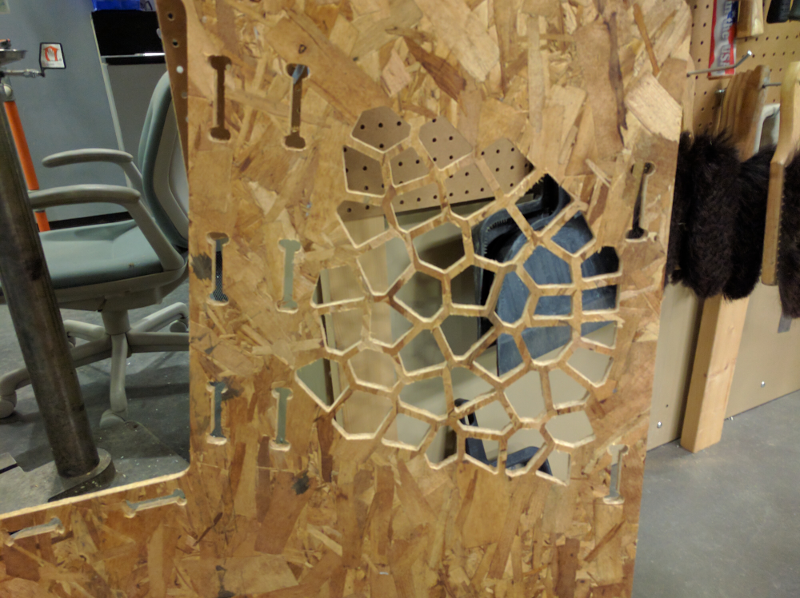
Stefania designed a beautiful pattern that we decided to project onto the side of the cabinet. We thought it would look nice to line the inside of the pattern with a lightly opaque material with RGB LEDs shining through. The ShopBot handled the intracacy of the pattern wonderfully.
With all of the parts cutout it was now time for assembly. We were a bit worried that we might have to use wood glue or screws to secure the cabinet once it was assmebled. However, once we started hammering (with a rubber mallet) the pieces together we discovered how strong the press fit really was. Another thing we realized is that we should have engraved identifiers into the parts using the ShopBot. Many of the parts looked the same so it was a bit of a puzzle assembling everything.
After a lot of hammering, rotating, and a little swearing we got it assembled.
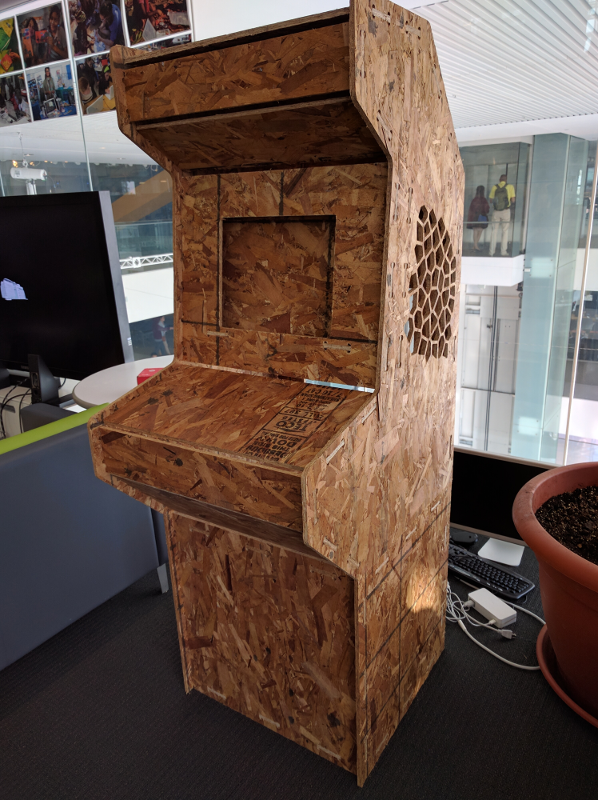
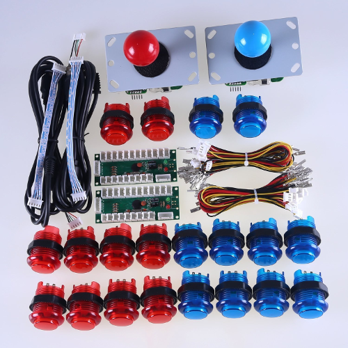
The screen hole was designed around a 15" LCD monitor that we had lying around. We also ordered two sets of buttons and joysticks, but unfortunately they are scheduled to arrive on the day of class. We might decide to stuff it with the electronics to create a working cabinet, or we might use this as a test for our final design with nicer quality wood. Some people have commented that they like the raw look of the OSB material.