
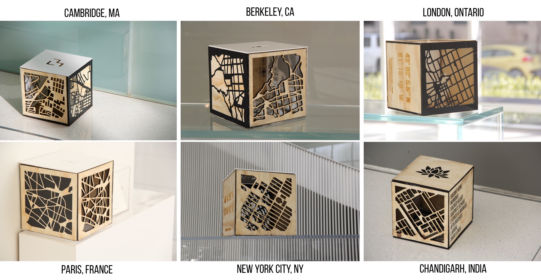
The City Blocks Project is a modular stacking system that can be used as lighting, shelving, or just general decoration in a home. The design of each cube is based on one of the cities I’ve lived in and integrates different elements like maps, images, words, latitude & longitude locations, and words in a variety of textures based on memories from each place.
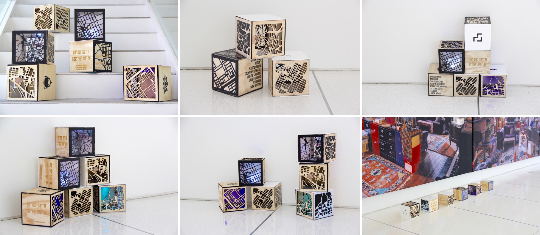
The boxes can be stacked in an infinite number of ways to create a range of aesthetics. Each box is powered individually so can be placed anywhere without constraints.
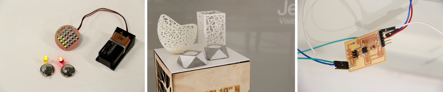
The project includes a “lighting kit” to create all sorts of aesthetics. 3D printing and molding & casting are used to create “sculptures” to change how the light diffuses in the box. Little LEDs and charlieplexed buttons can be used to signify locations on the boxes. The NeoPixel LEDs used inside can be programmed to display different colors.
I came to How to Make (Almost) Anything with basically no experience in any of the tools and techniques we learned other than 3D printing. I had 3D printed a fair amount of stuff during my undergraduate degree and laser cut a couple gear shapes. So everything was new!
During the semester, I was really interested in playing around with the idea of modular designs for the home. I wanted to create things for my apartment that could be used in many different ways depending on the need. Over the semester, I tried to integrate these ideas into my projects. A few examples of this can be found here:
I moved around a lot in the past few years and I was always interested in exploring different ways to trigger memories from each of those places within my environment. This is where the idea of creating these city blocks came about.
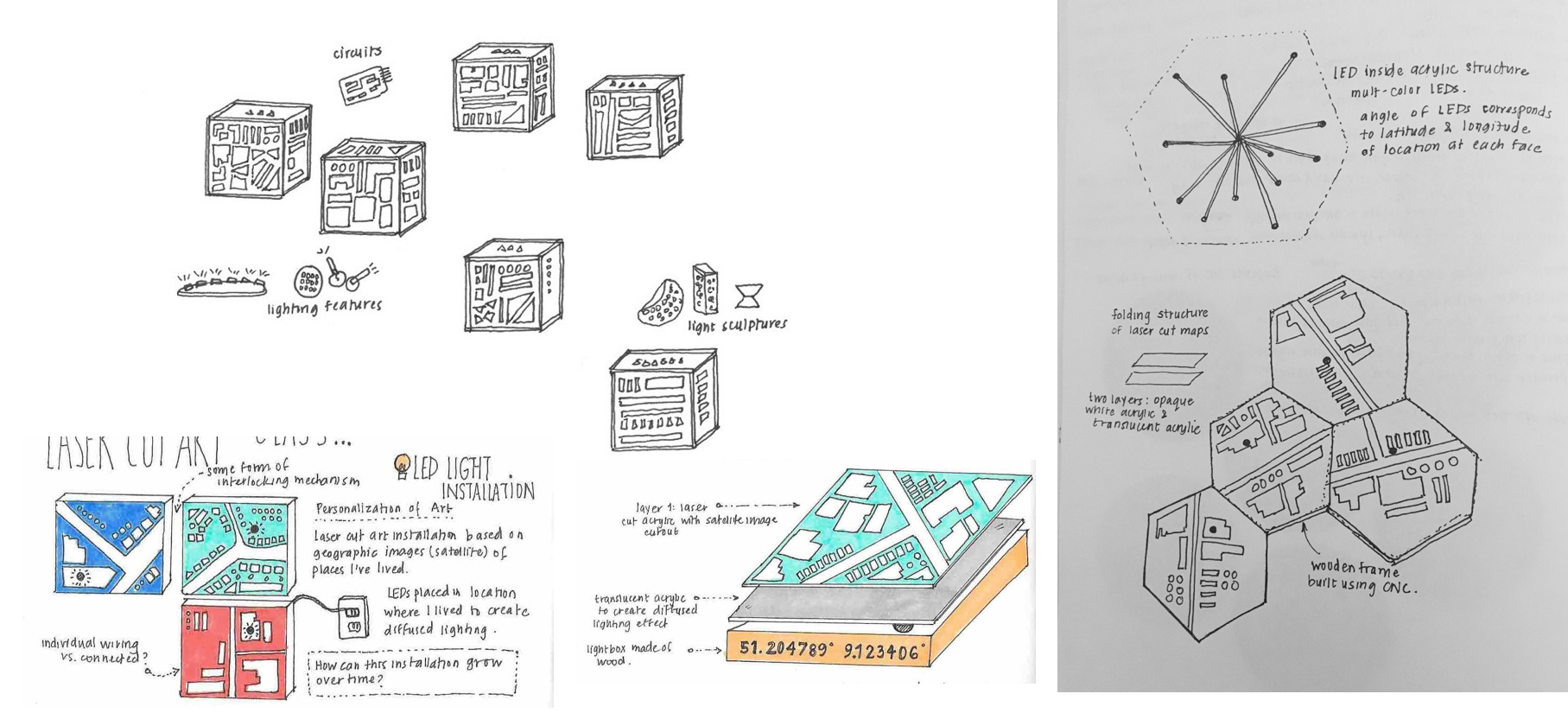
Above is a few snapshots from various brainstorms I went through to come up with the idea. Initially, I was planning on making them into thin frame like features that could be hung up on a wall. Then, the idea transitioned to creating a large geometric shape with each face representing one city. Eventually, I decided to create individual boxes, where each box would have the “personality” of the city it represents. There were a few reasons I chose this approach over the others I came up with:
The concept and design of The City Blocks is entirely mine. I drew inspiration from lighting installations and lamps with laser cutouts.
The materials needed to complete this project are listed below. Note that for the demo, I did not stuff each of the boxes with the necessary NeoPixel rings due to time and availability constraints. However, the methodology used for one box can be replicated across each. If the total project was made from scratch, the cost would be $214.00. However, since I was able to gather a lot of the materials from the scrap pile and from the lab, it cost me about $85.00.
The first challenge in the project was actually getting the maps vectorized. At first I thought Google Maps would be the expected go-to for this purpose. However, creating clean vectors from the images in Google Maps proved to be quite difficult and it was difficult to get the right aesthetic. After a couple hours of Googling I found a few good resources.
I ended up using the technique in the Instructable to create the vectors. My initial vectors had really thin features, so I ended up using the “contour” functionality in CorelDraw to do an internal contour by 0.05 inches in order to make the roads and thin edges wider. After a bit of detailed editing on each, I had a set of 6 vectorized maps ready to go!
In designing the form factor of the boxes, I had a few key considerations in mind:
With these in mind, I started the box building! The first step was to cut my giant pieces of wood into smaller ones so that they would fit on the laser cutter. I also wasn’t sure if I wanted to use the Shopbot to cut the outlines or use the laser cutter. When I first tried with the Shopbot, I realized I liked the aesthetic of the burned darker edges. It added depth to the maps so I decided to just cut the wood into smaller pieces using the saw and then using the laser cutter.
Even when I did the contour, the maps were really difficult to cut consistently. The wood I had was a bit warped. It wasn’t when I bought it but my guess is that it got warped from moisture since it was leaned against a concrete wall in my lab. Because it was uneven, the laser cutter wasn’t able to cut through evenly everywhere. I tried with a lot of different settings and kept getting mixed results. The picture on the top left corner shows the results I was getting. So I went back and thickened the roads even more and slowed down the laser cutter speed. The settings that eventually worked were 0.3 speed, 100 Power, and 80 PPI for the 1/8″ plywood. This was painstakingly slow to finish but atleast they always cut through!
The acrylic was a lot easier to actually get cut. I ended up using 0.7 speed, 100 Power and 500 PPI for the acrylic sheets. I then used the vinyl cutter to cut out the maps and ended up using both the positives and negatives to create different aesthetics on the acrylic and wood. This gave me a cool set of 6 sides for each map, with some simple sides and others with more complex maps. I also did some vinyl cutting of words related to memories in each place. These were a bit tricker to transfer over since some letters were so tiny (particularly the letter I), so I just ended up vinyl cutting a bunch of extra of these letters and fixing any missed ones.
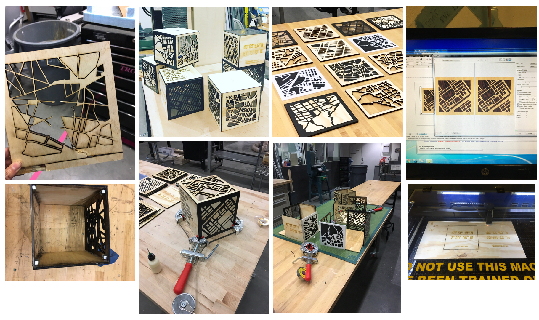
Once the sides for the blocks were finished, I went searching for adhesives to put everything together. First I tried wood glue. This worked fine for the plywood pieces but was a struggle when adhering acrylic to wood. A found a four way 90 degree clamp to help with the box-building. However, because some of the wood pieces were a little warped, it was hard to get it to work with four pieces. To work around this, I ended up making corners with two pieces at a time. I placed extra plywood pieces in between to separate the corners. Once the corners solidified, I used hot glue and epoxy to put them together into a cube.
Finally, I wanted one side on each box to be detachable so I would be able to put in the electronics pieces. I got little magnets and found some bolts in the machine shop. I placed the magnet and bolt together, applied hot glue to one side at a time, and aligned them on the internal corners of the box. This enabled me to get pretty good alignment of the magnets and one of the box faces. I realized the clear 1/4″ acrylic was a bit heavy to stick with magnets so tried to use the thinner 1/8″ acrylic sides as the detachable ones.
My original goal for the electronics was to create a modular “lighting kit” of sorts. I wanted to make a bunch of different lighting effects that could be used in different ways to make varied aesthetics. I also wanted the electronics to be flexible so I could build on them over time. I had all sorts of fun ideas of things I could do with the boxes like:
I knew many of these were ambitious given that I had no exposure to electronics in the past and was still trying to pick up the basics. However, I thought I’d give it shot! Unfortunately, the two weeks of electronics struggles that ensued after suggested otherwise! Below is a few of the boards that failed and all the reasons why.
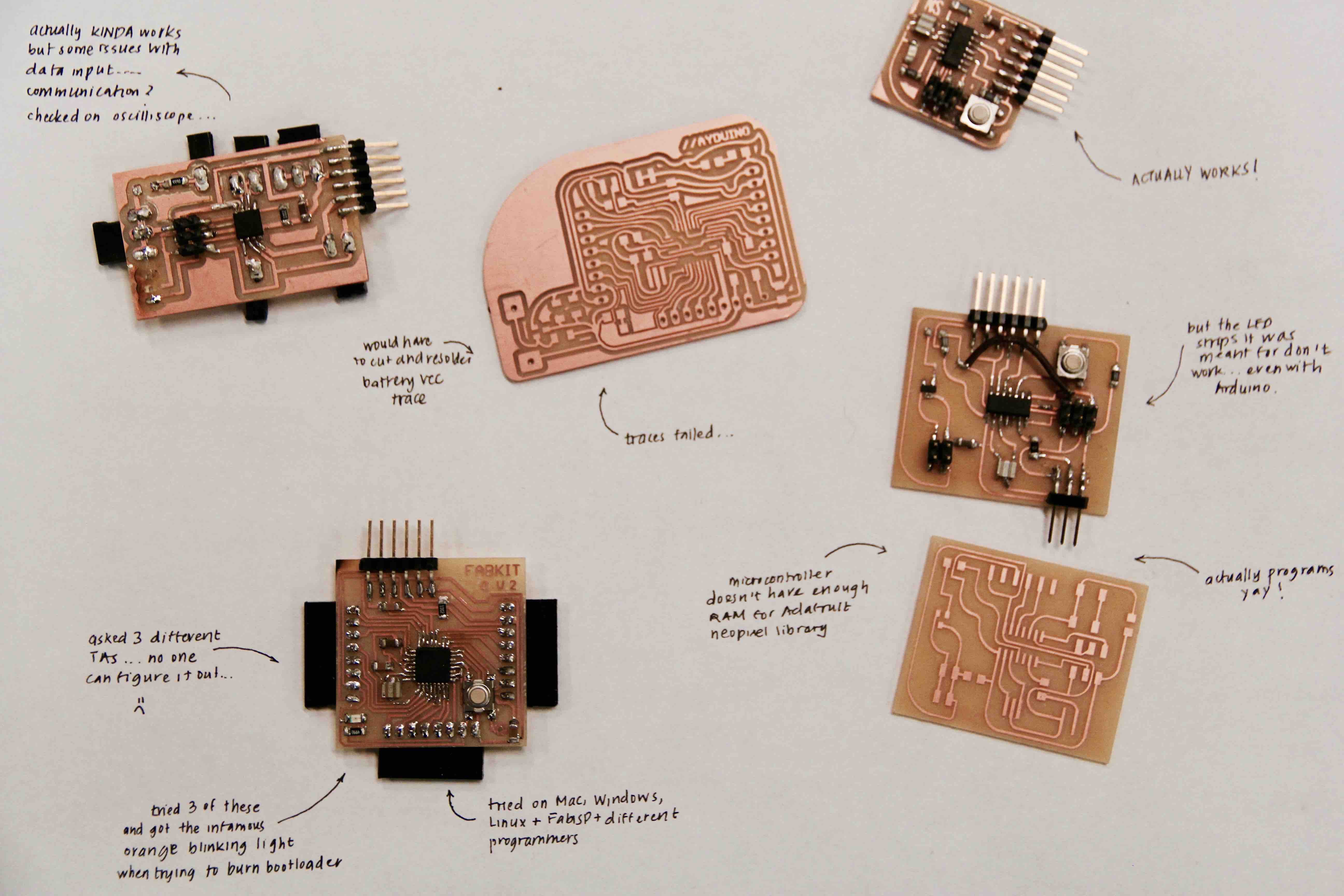
Attempt #1; The myth of the Fabduino & the infamous orange blinking light
My initial plan was to try and create the Fabduino. I saw a lot of people had used it for their projects last year and it seemed compelling to have a modular board like an Arduino that I could change around depending on the purpose. All great in theory right? Enter reality.I attempted making a Fabduino three different times and each time had failures. The first one had messed up traces due to an overused endmill so I had to ditch the board. The second time I ended up burning some traces while using the heat gun to replace the microcontroller while debugging. The third time I had a viable board but we couldn’t figure out the problem. I worked with the TAs (thank you Brian, Sam, Amanda and Eric) to debug each time, but we could never conclusively figure out what was wrong. Every time I connected the board to the programmer, I got an orange blinking light which generally means something is wrong with the reset line or the the ISP header is on backwards. Things I tried to fix it were:
Unfortunately, neither me or the TA’s could find a reason why it wasn’t working. This was also when we I ended up being called in class to review my project. Neil mentioned that the Fabduino is not necessary for every project. With this in mind, I decided to go back to the drawing board and rethink how I was going about the electronics problem.
Attempt #2: Breaking it down into simpler components and the annoying world of NeoPixels
Even though my electronics were constantly failing, I realized I was getting much better at debugging. Previously, I often had to Google or ask classmates for help on which things to check when a board didn’t work. I was (slowly, but surely) getting much better at having an intuition for what to check. I knew when it made sense to replace the microcontroller and how to triage and do basic checks. With this in mind, I decided to breakdown my electronics goal into smaller components and try and work on simple solutions. If I found the time to make an elaborate thing later, I would, but at least this way I would have working elements and could focus on learning basics rather than trying to desperately hack something together.
This approach ended up being a lot better in many ways, though there was still a lot of failure. The first goal I decided to take on was getting the WS2812B LED strips I had working. More details on this can also be found here, but I will go through some of the process on this page.
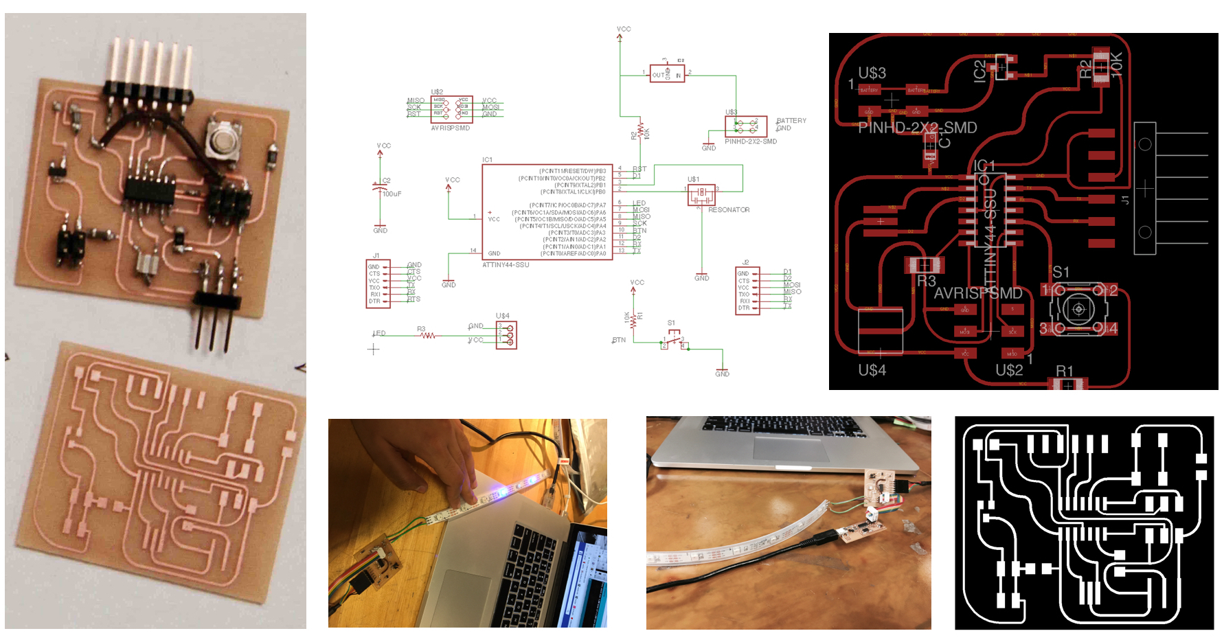
Upside? I managed to debug the board. I realized I was a missing a trace on the reset line so put a wire there. I also reconfigured things a bit to deal with the dropoff voltage from using a 5V regulator when I was connecting it to a FTDI cable. After a couple quick changes, the board programmed pretty easily. I loaded some some sample code from the Adafruit Neopixel library for Arduino IDE. Unfortunately, the LED strip decided not to work other than lighting up a couple small LEDs. I Figured it might be because I used a ATTiny44 and the Adafruit Neopixel library requires a lot of RAM due to all the dependencies.
As a final pass at these LEDs, I thought I would test them on Arduino to make sure they were working. In retrospect, I probably should have done this earlier, but better late than never! When I tested on Arduino, they still didn’t work which made me think there was likely an issue with them or I was completely messing up the code. I asked some of the TAs for help and it seemed like the LEDs may have been blown out so I figured I would AGAIN go back to the drawing board and find some new ones.
Attempt #3: The NeoPixel ring and timing struggles
One of the other students in the section showed me some NeoPixel rings she had used in the past. She mentioned that she had also had trouble with the WS2812B strips but the NeoPixel rings were easier to get working. Finally, some hope!
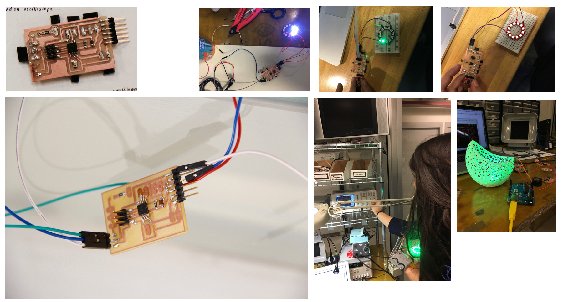
I decided to learn from my mistakes and prototype the circuit on a breadboard using Arduino this time first. I was not going to sink a ton of time in debugging a board with the output I was trying to create wasn’t working to begin with. That experience definitely taught me to not take anything for granted with doing DIY projects. I prototyped the circuit and the NeoPixel rings worked great. I figured this would be the winning board! Initially, I wanted to complicate things a bit and add a bunch of flexibility to the board, but figured I would go really simple with an Attiny45 (since I really only needed a data input pin) for the LED. I designed and made a board and split out the locations of some of the remaining pins so I could use them later if the board worked. I also spent a lot of time looking through old documentation from people who had used similar LED strips in their projects to get a sense of boards that worked. I found someone had been able to power NeoPixels (though not exactly the same) with a similar Attiny45 board so I thought I would start there and build up.
The Attiny45 board was a bit temperamental. I could get a couple pixels to light up but not all of them. I could however program them to be different colors. Amanda helped me debug using the oscilliscope. We checked the signal on the Arduino to see what it should look like and then checked it on the Attiny45. There was some signal going through but it didn’t quite look the same as that on the Arduino. Some Google-ing revealed that it may be a good idea to switch to the ATtiny85 since it seems to be better supported by the Adafruit Neopixel library. I also looked into using a lighter weight C library and found this and dug into how the Neopixels actually work. Switching to the Attiny85 helped and I was able to get all the LEDs to light up using the Arduino IDE and the Adafruit Neopixel library. I tried different colors to get a sense for what worked and didn’t. Its still a bit finicky unfortunately, but I was happy I got something working! Its definitely something I can build on. I ended up using battery powered LEDs for a couple of the boxes since I had them laying around and didn't want to spend the money to buy all the NeoPixel rings for all the boxes. I figured I would focus on building unique elements and repeating them for all the boxes could be a consideration for another time. Atleast by combining these, I'd be able to show a solid proof of concept!
Location lighting: Charlieplexing and magnet LEDs
In addition to lighting the inside of the box, I wanted to make little LED buttons to light attach to various locations on the map. I also thought this would be a nice break from working with the Neopixels since after spending six days debugging them, I was a bit exhausted. I came up with a bunch of cool ideas to implement.
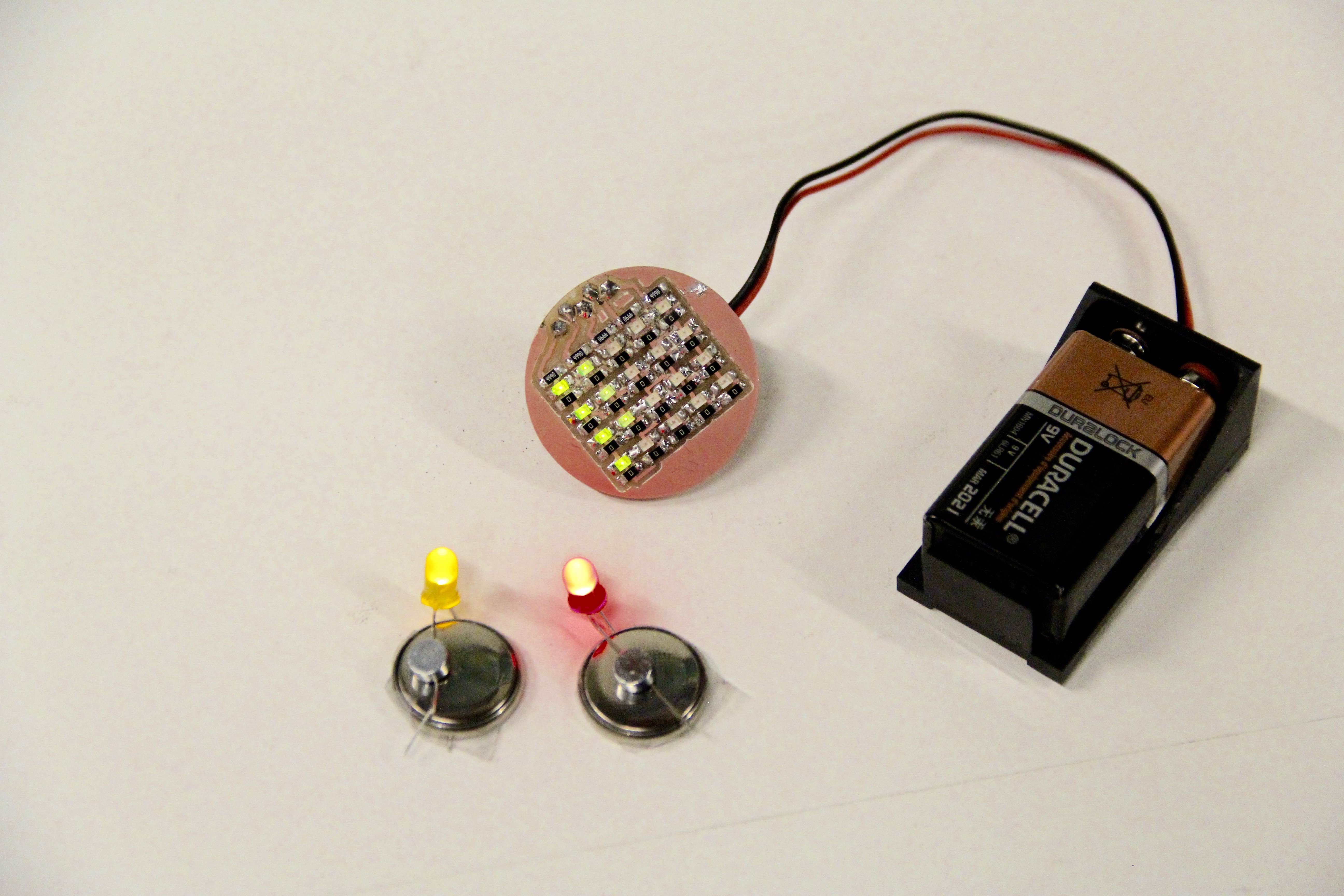
I decided to tackle (1) and (2) given that I only had a bit of time left before the project was due. Using Neil’s demo board for the Charlieplexing as reference, I made a circular two-sided board as a “button” of sorts. I programmed the board by playing around with the C code Neil provided. A couple of the LEDs didn’t end up working perfectly, but for the most part it looks pretty good! For the time being, I made it so it lights in a triangle pointing in the direction of my “home” on the map, but hopefully I can try some fun things like letters or distribution patterns to show where I spent the majority of my time in the given city.
I also made some mini button cell LEDs. I glued a magnet onto the back of the maps on the boxes in the location of my work and home. This way, when the LED and button cell was attached to the magnet, it forced the other end to touch the cell and turn the LED on. I used two different colors so I could signify “home” and “work” locations differently, but you could use these to make any pattern!
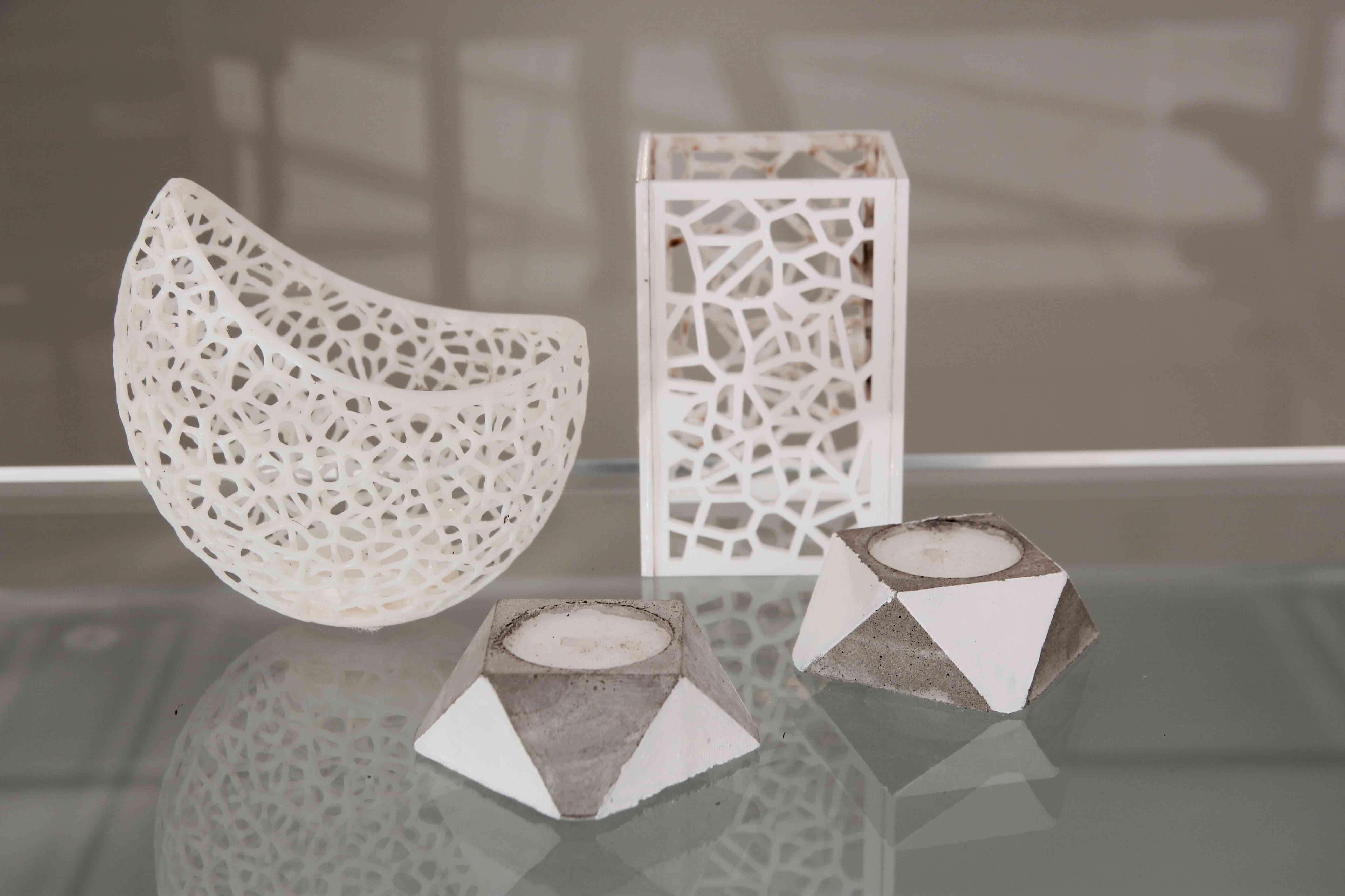
To further reinforce the modular concept, I wanted to make a series of “sculptures” to change the lighting effect inside the box. To do this, I used 3D printing, laser cutting, and molding & casting.
3D Printing
I’d seen many implementations of the Voronoi pattern on 3D prints and they always looked really cool! I looked around the internet and found some cool organic shapes and decided to give my own version a shot. Theres a bunch of tools that help you make the pattern:
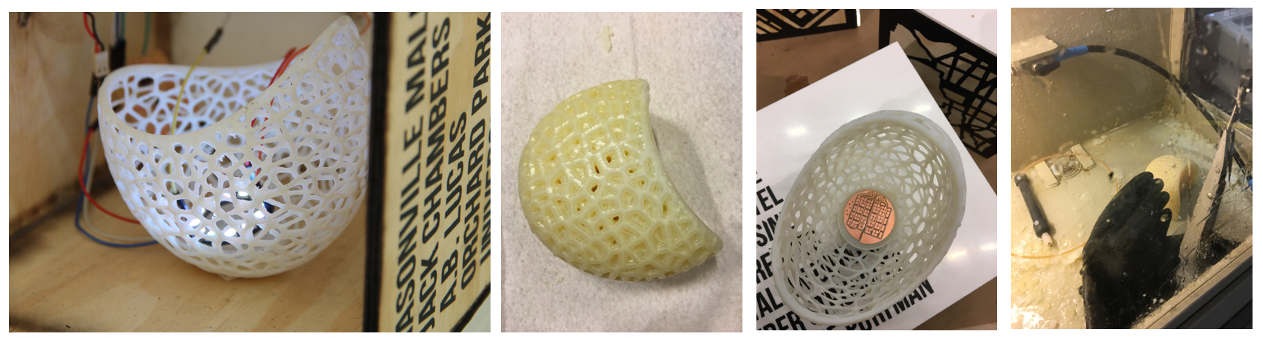
I printed the model on the Eden and also tried it on the Mojo in my lab. The attempt with the Mojo entirely failed even though I put the maximum support material. I guess the resolution of the printer just wasn’t high enough. Many of the layers were just coming apart and after the chemical path, the model was just broken into a bunch of small pieces. The Eden print turned out great. I used the water jet to get rid of the support material. I put an inner casing to fit the NeoPixel ring or the Charlieplexed button to really make sure that all the pieces could be fit together.
Molding and Casting
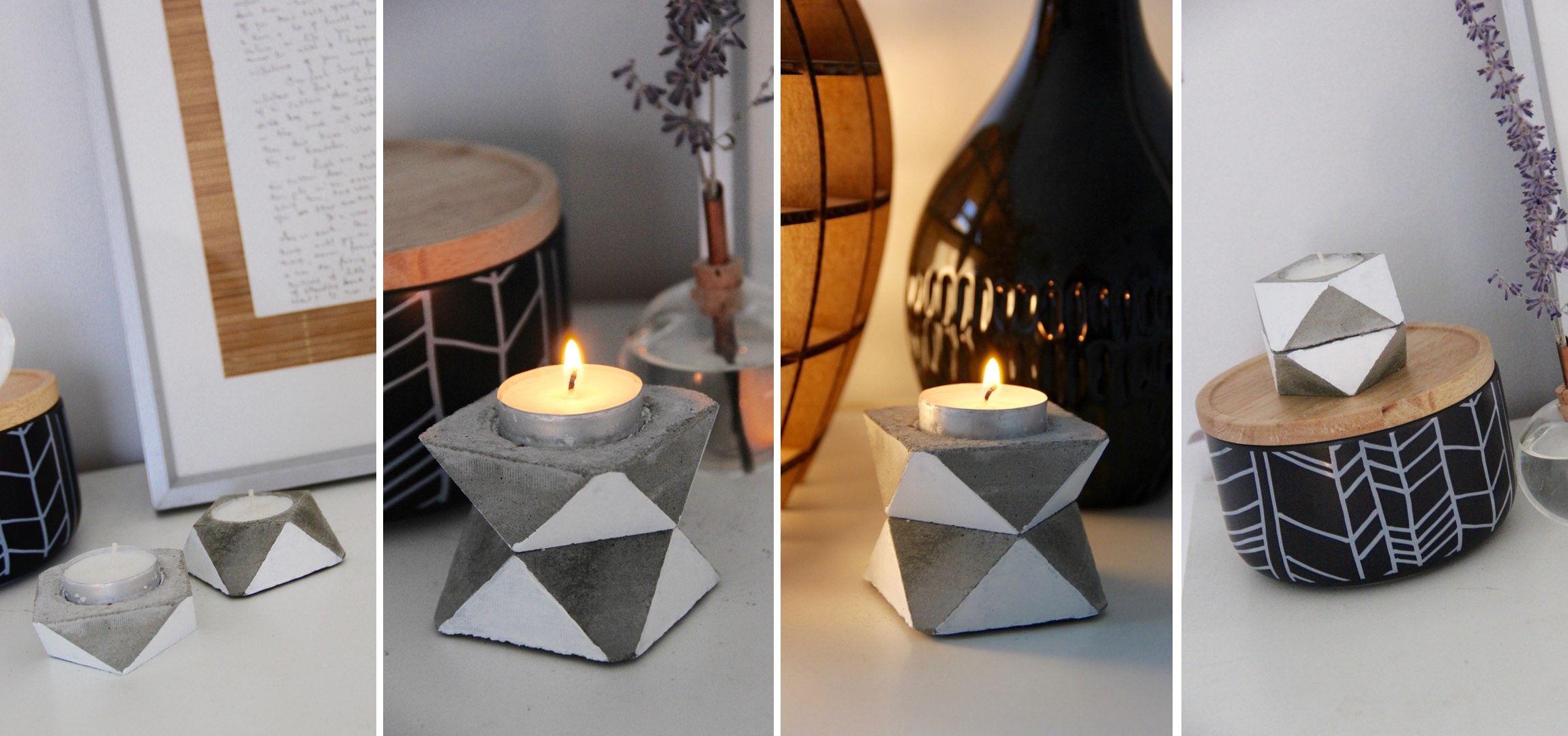
I used my design for the cement stackable candles from molding and casting week to create a set of holders where the hole had the same width as the Charlieplexed button and the NeoPixel ring so it could be inserted in at varying heights depending on how the candles were stacked. Alternatively, the magnetic part of the box could also be removed and a candle could be lit inside.
I figured if I had all the pieces this wouldn’t take very long. I figured I would put together the MVP and go back to enhancing my NeoPixel circuits. However, things always take much longer than you expect! I wanted to be clean about the way I put the pieces together. I got Velcro pieces to attach at different parts of the box to enable different lighting configurations. I also used battery packs and soldered wires accordingly to make sure the connections were good. Putting all these pieces together well took a fair bit of time. I also had mini failures along the way like my FTDI header coming off my board and NeoPixels misbehaving which took some time to fix.

I started this class having never done most of the technologies we learned. I had basically used a laser cutter once and 3D printed a bunch of things. Its kind of awesome to see how much you can learn in a semester. Even though I didn’t get to finish as much as I originally wanted to with my project, I felt like I grew a lot in terms of building intuitions for how to tackle problems. With electronics, I was much better at having a sense for what could possible be wrong. With laser cutting, I knew how to adjust settings and how to work around issues. With 3D printing, I had a much better sense for tolerances and what the 3D printer could or could not handle. I also learned how complex it can be to get all the moving parts to work. Even though initially I found myself gravitating towards doing one part of the project at a time, working across the domains and doing the simple version of ideas first proved to be the better strategy to getting a minimum viable product done.
I want to keep building on my knowledge of these skills, most importantly electronics. I feel like I’d like to build a more foundational understanding of the different aspects. The City Blocks are a good mechanism for me to continue furthering my understanding of electronics. I hope to be able to build some of the functionality I had brainstormed and make each block more interactive than its current state. Some ideas for building on it are:
I hope to be able to leverage the kit of blocks and lighting I have built as a way to learn many of these skills and explore new ideas.
The modularity of the elements is also a powerful basis to build on. There is an infinite number of configurations and aesthetics that can be created from a small set of elements. I think this can be a really powerful development strategy, especially during the learning process, since its possible to break down larger problems into smaller, more conquerable ones.
All in all, its been a great semester and I’m excited to come up with new ideas to apply all the skills I’ve learned!