FINAL PROJECT: _ integrate all the fabrication methods.
Inhabitable Exhibit
The Museum Display Case of Microbial Life.
CONTENTS:
[1] Computer Aided Design: box exterior and interior plans.
[2] Laser Cutting Press Fit: outer containment housing and lock.
[3] CNC Machining Vacuum Forming: custom insulation, inner humidity chamber.
[4] Electronic Inputs Networking: serial boards for temperature sensing gradient.
[5] Electronic Output Power Supply: home-made heating element and fan.
[6] Molding Casting: heating element plates.
[7] Interface Programming: temperature converter, display, and thermistat feedback loop control.
[8] 3D Printing: custom lab ware.
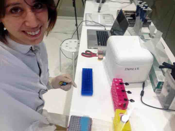
The Inhabitable Exhibit is a vehicle by which to push microbial tools, processes and designs into public 'spaces'; to give the necessary public presence to the organisms behind the salient technological advances in microbiology. I hope to push the bounds of what interactions people are currently comfortable with, with bacteria.
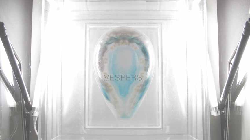
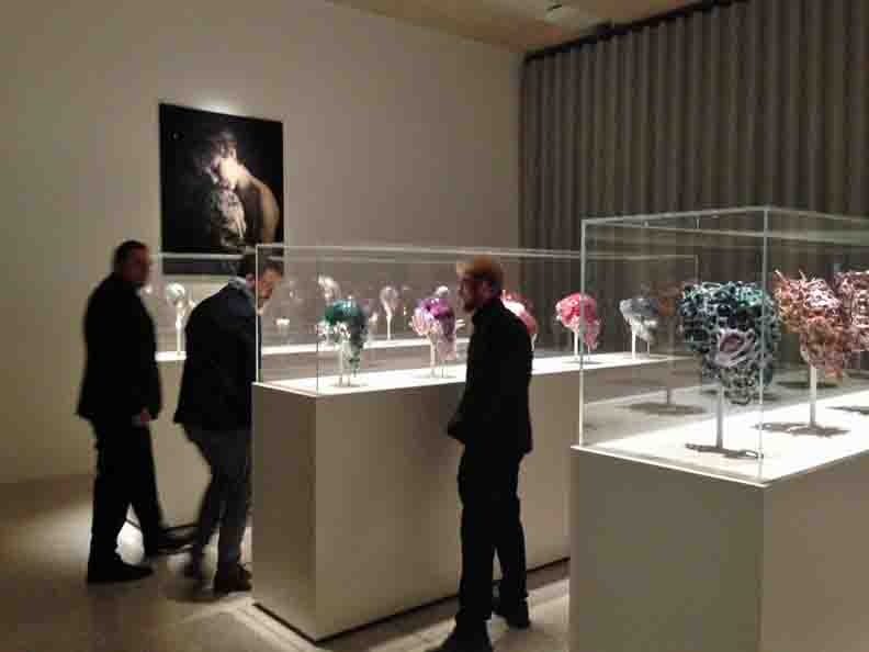
BACKSTORY: In the last month, I worked with my research team to release a series of microbial pigmented masks to the London Design Museum [PIC/LINK]. Our masks were completely inert: dried, UV-cured and covered in varnish, and yet it was a logistical victory to achieve. While our world and bodies are swathed in microbial life, and many ancient processes like fermenting are very comfortable with the idea of culturing and connecting with microbes, modern society is very squeemish of the idea. I realized that it is indeed no small feat to get bacterially 'processed' objects into a museum. Thus, I want to poke at the idea...
In my plans for Living Display Case - I want a way for *living* microbes to be displayed, observable through their dynamic growth or lifecycles, and maybe even adored. This requires:
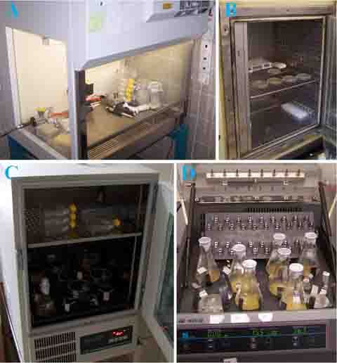
> Function: DIY Incubator, with thermostat and humidistat environmental control (electronics).
> Physical Form: An isolated unit with two levels of containment, fit for transport outside of a biological lab.
> Design Form: A plinth fit for the Louvre! Non-trivial, this is how I present bacteria to the world and I want it to be viewed as both beautiful and valuable.
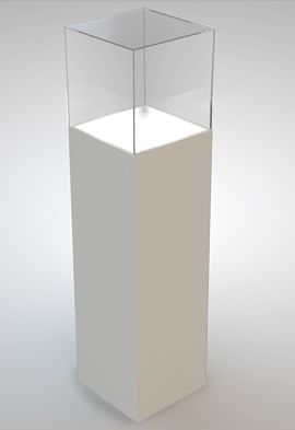
To avoid spiral development I've decided that a worthy task would be to create the feedback control loop of a thermostat within the electronics realm, and to create feasible containment out of my physical fabrication skills. Aesthetically and design - wise it is presented as a plinth for art or design museums, and the 3D printed object becomes the subject of interest inside.
Computer-Aided Design
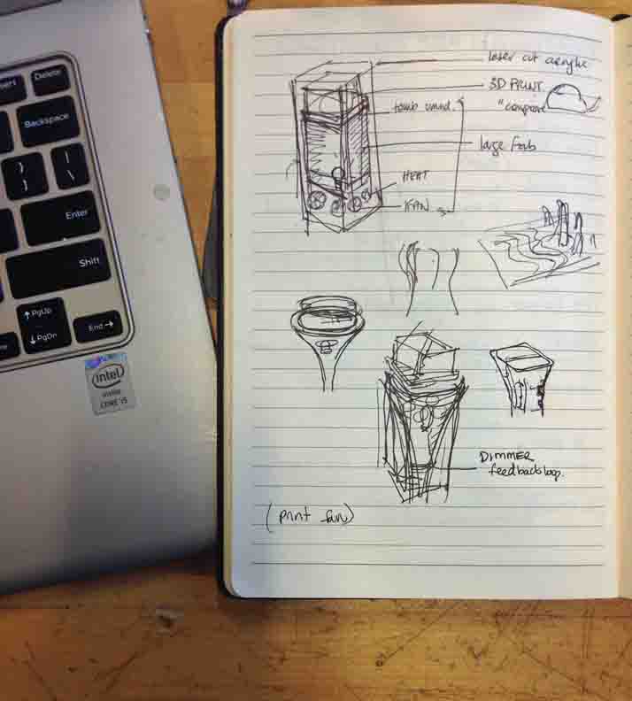
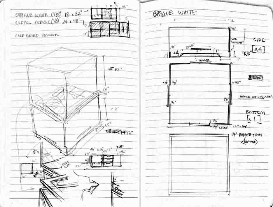
Beginning with my natural state, pencil and paper.
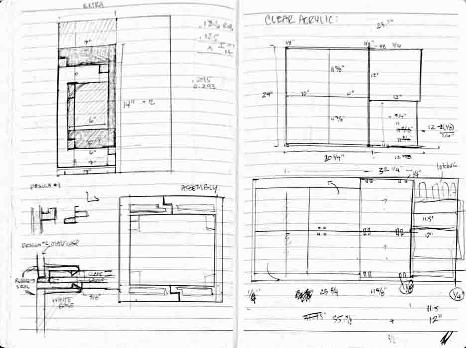
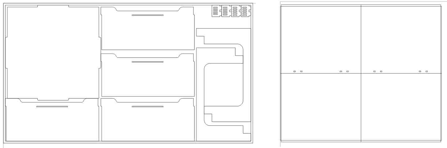
I transferred my technical drawings into design software OnShape, which is a free in-browser 3D system very similar to SolidWorks. I used it to help with process planning, material estimates. With OnShape, I can export as DXF files for 2D applications and STL for 3D applications, and as learned in Week 1, I can assemble with parametric settings.
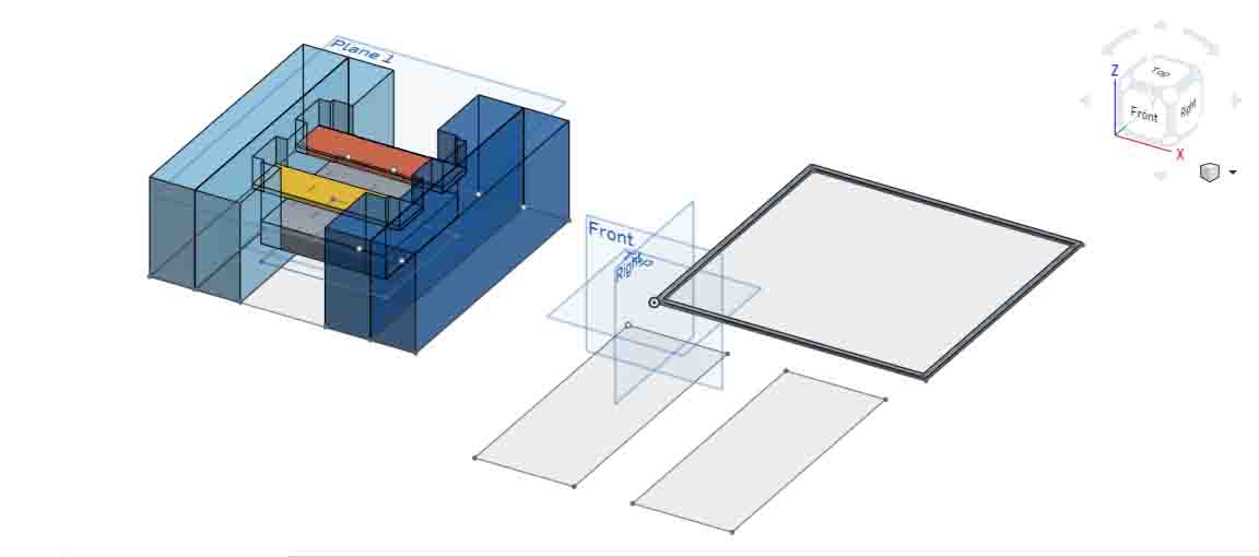
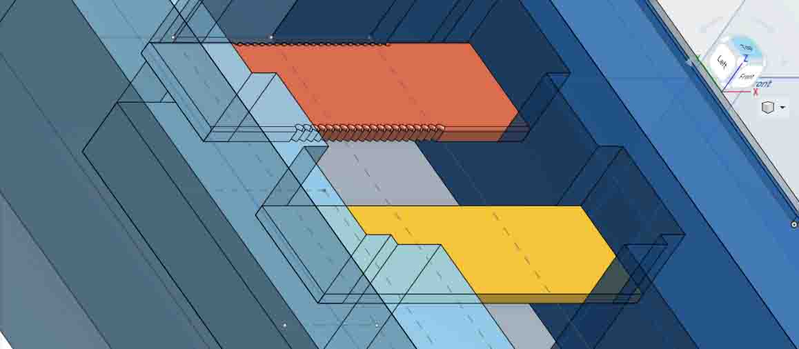
Above are plans for the base and body of the incubator. They are available publically online at BoxInterior and BoxExterior . They are good for play with the design and adjusting some parameterized dimensions, although I suggest if you are trying to recreate this, you stick to the Laser Cut plans and ShopBot toolpaths below. I next transferred these shapes to 32"x 18" cutting sheets for the laser cutter, in CorelDraw.
Laser Cutting and Press Fit
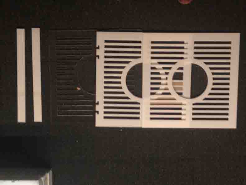
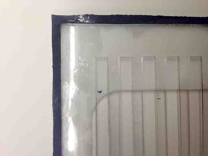
It is always good to characterize your material before designing press-fit joints (call-out Week 1!). I'm cutting 1/8" white and clear Plexiglas acrylic, so I've designed test pieces to measure my joints as well as the power settings for a clean cut. (> feeds back into parametric design)
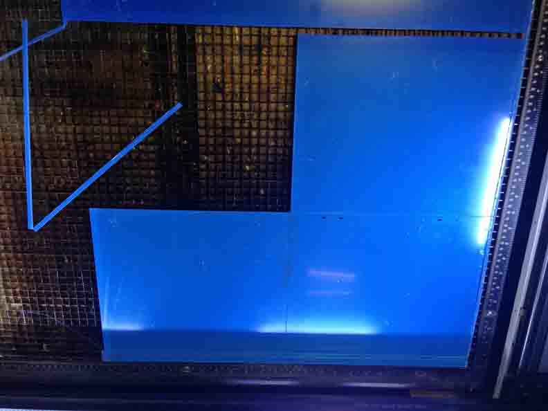
As a museum case, I'm aiming for smooth and monolithic. I designed to make seams discrete. Gluing flat cuts of acrylic is do-able, but is a risky sacrifice of alignment. I have minimized the number of finger joints to one, single jag near the foot of the base. It's non obtrusive and does its job. For the clean upper, I took the risk.
> Acrylic sheets can be $30 a pop! If you are a cheap student like me, you will want to cut as close to the edge of your material as possible. To do this, keep the paper/plastic protective film on the acrylic. Try Laser Cutting Settings: Speed 1.5, Power 100%, PPI: 1500 to quickly etch a "preview" into the sacrificial film, in order to make minor changes to the material's position in the print bed.
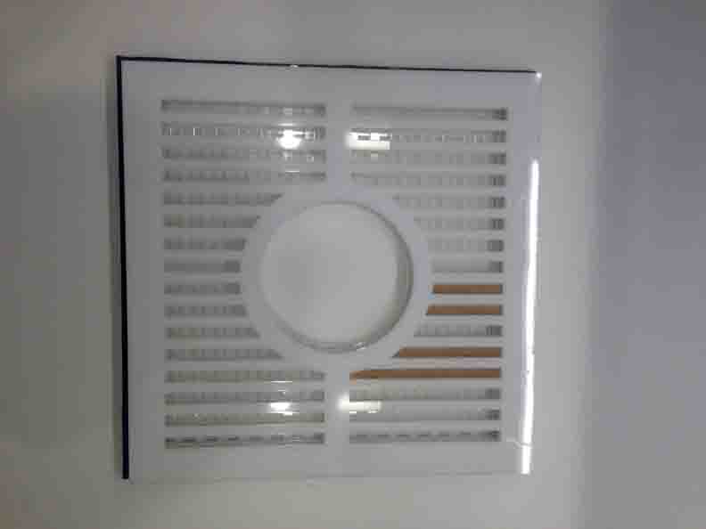
Finished Case:
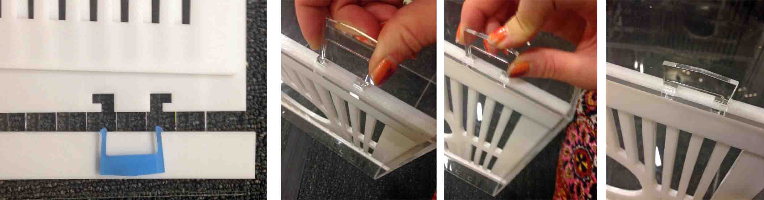
Spot-light: A press-fit strategy is used for the primary function of the external containment, the lock. I've included four barbed 'snaps' to fasten the lid shut. A user can squeeze them to release the top lid, but this is not meant to be done relatively often since it's primarily a display case. Since they are small, independent pieces, they can easily be replaced if broken.
CNC Machining and Vaccum Forming
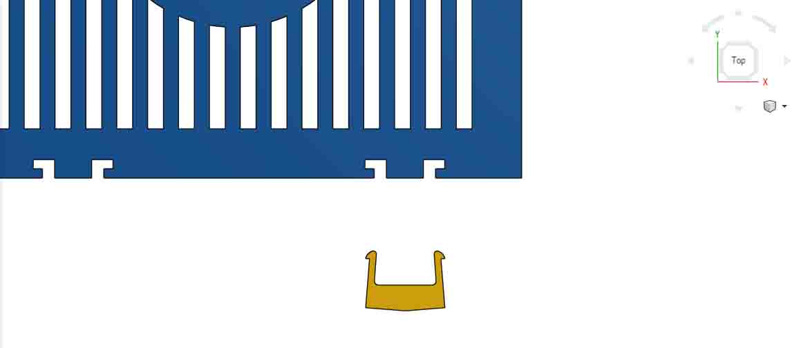
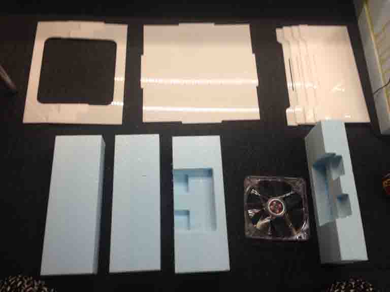
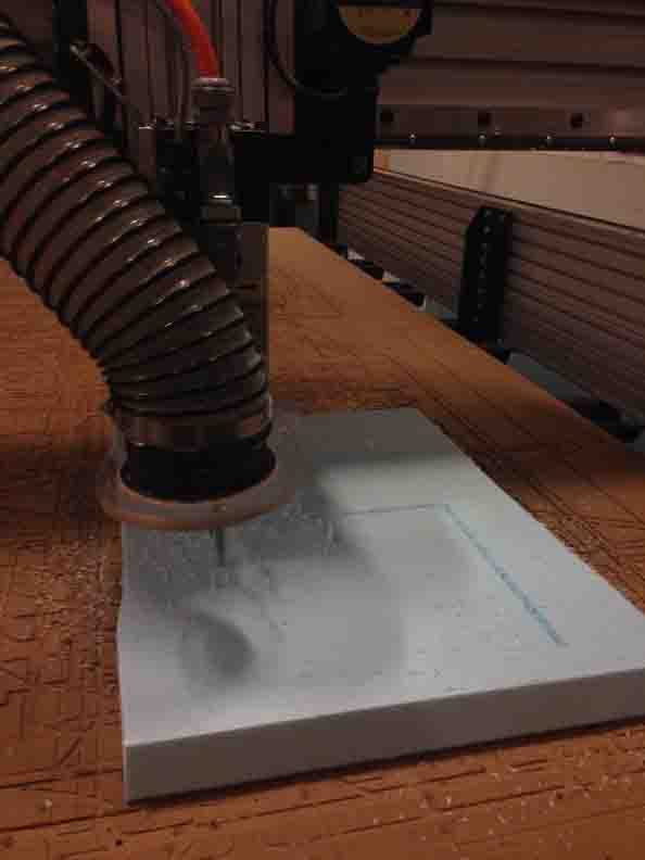
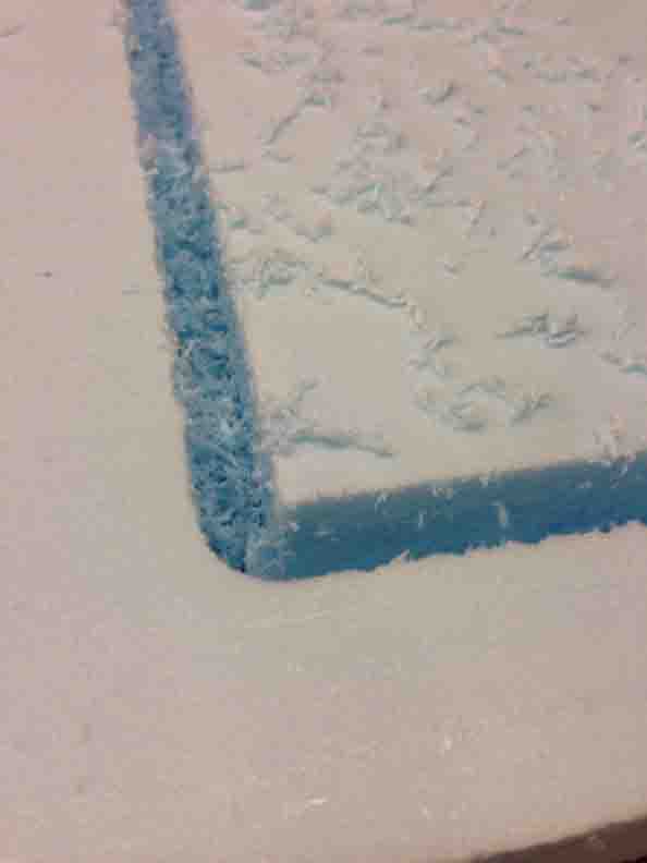
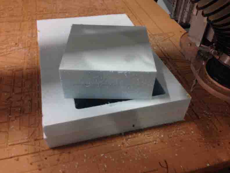
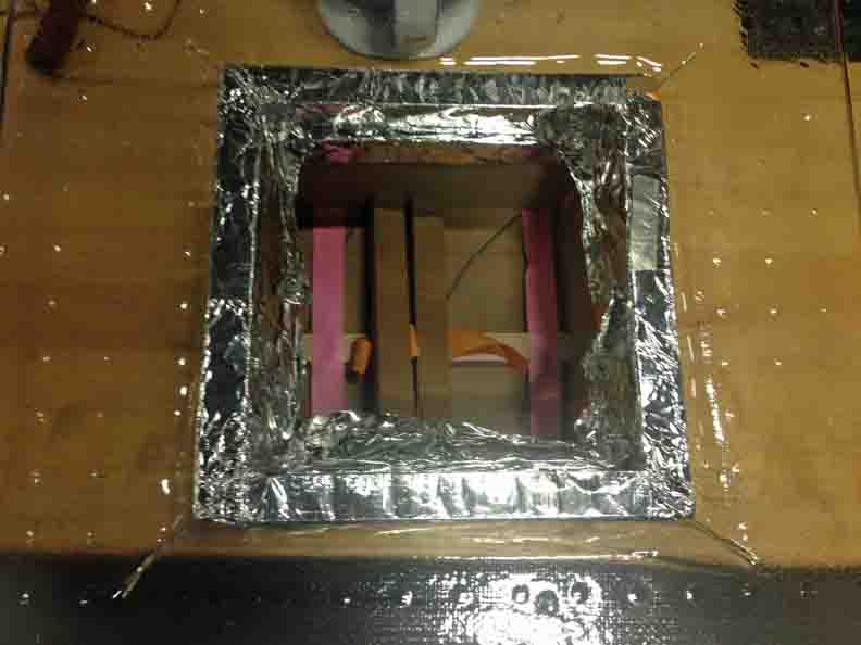
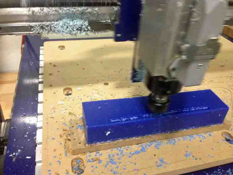
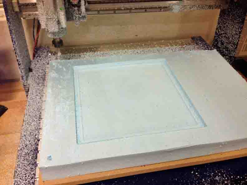
This shopbot is finally my best friend - both the desktop and large-scale mills were good fabrication fits for many components of the incubator. First up, I use the blue foam directly to insulate the base of the incubator. Here, it is cut to insulated the heating elements, and provide a self for a circulating fan a few inches from the heating element. (See CAD drawings). Rough and finishing toolpath for the shop bot included, using PartsWorks for 3D forms.
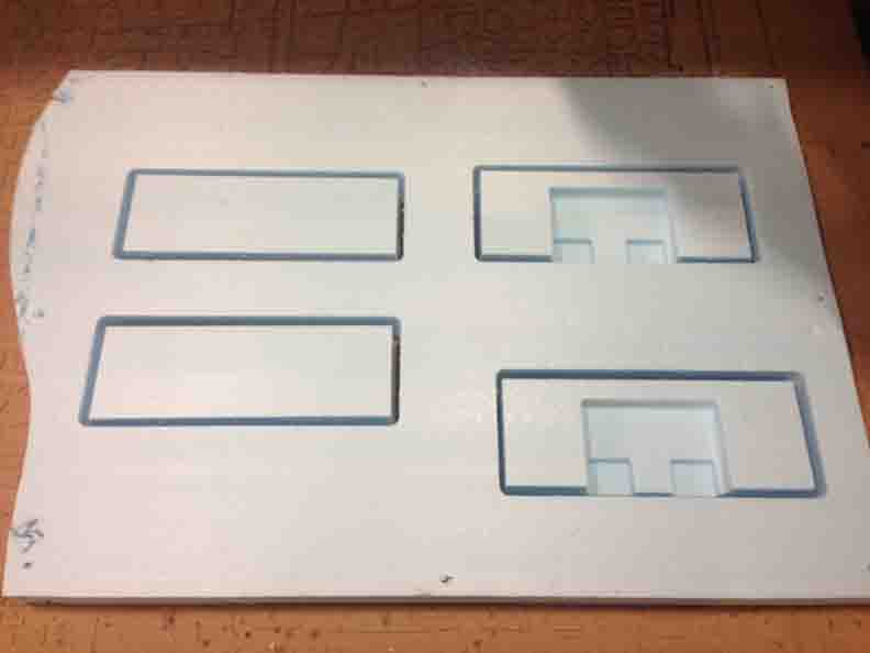
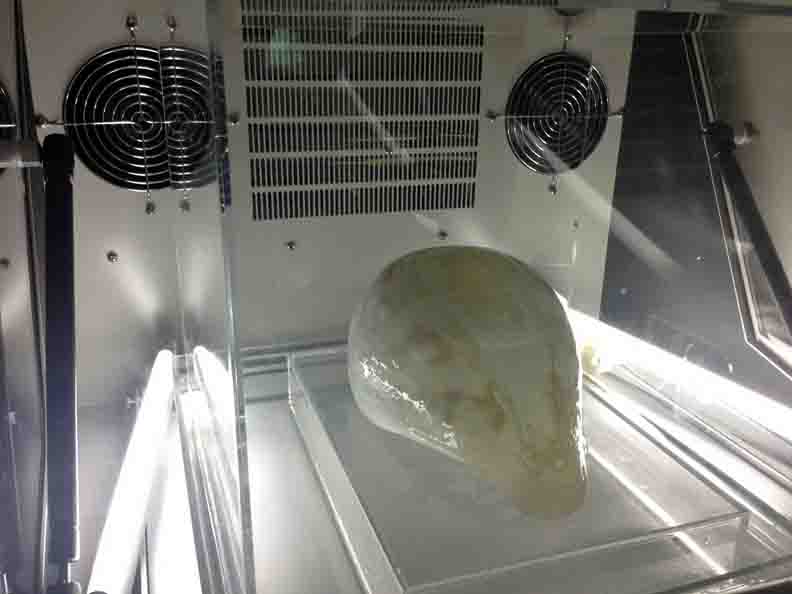
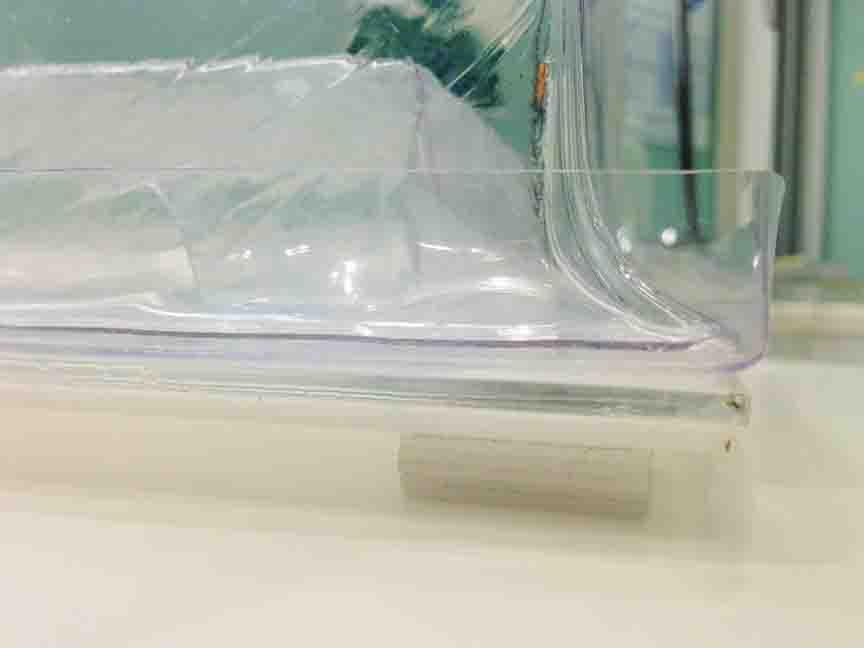
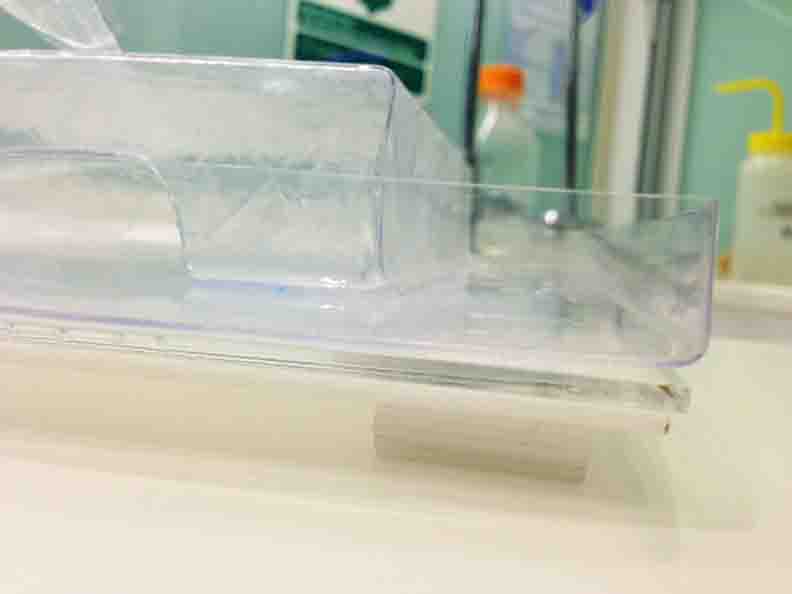
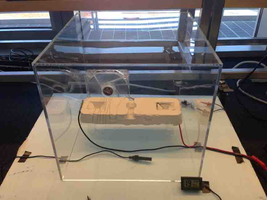
Second, I must fabricate an inner, secondary containment unit. It doubles as a humidity control chamber. Through experimentation, I can achieve near-100% humidity, passively, by making the base of the box a tray for water. The combination of the incubator's heat and the large surface area, creates consistent humidity. It's actually *BETTER* than driving water into the air with an electronic humidifier because it does not over-humidify and cause condensation - WHICH WOULD BE HORRIBLE FOR THE VIEWING EXPERIENCE!! :O Thus, a design constrain of the secondary containment is that it have a completely water tight base.
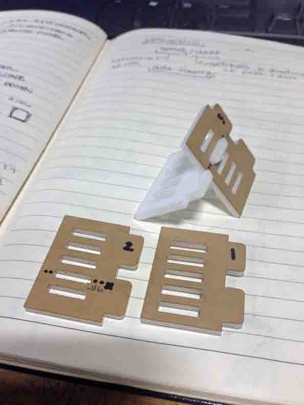
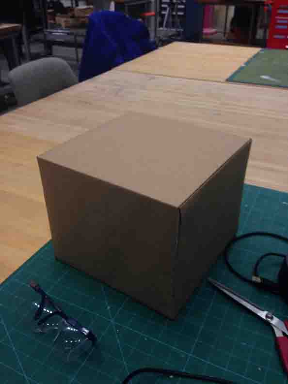
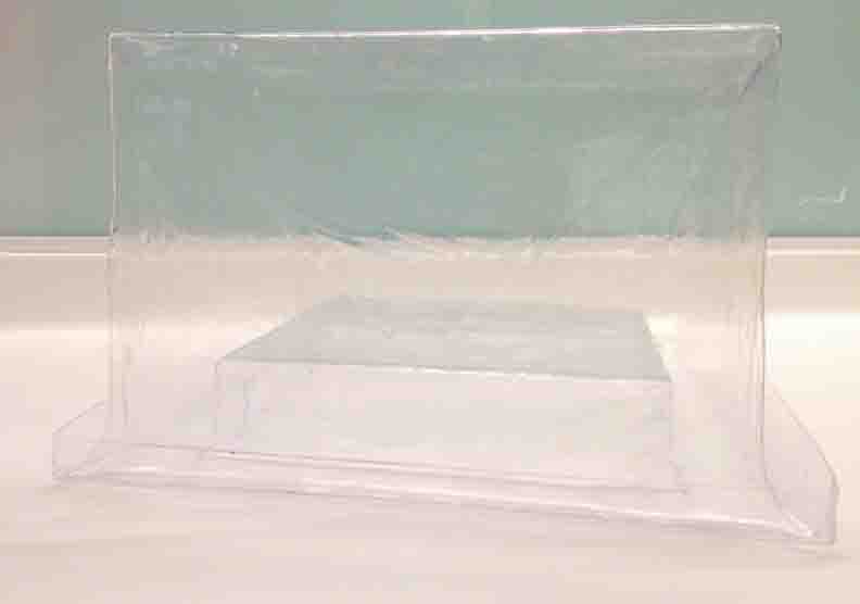
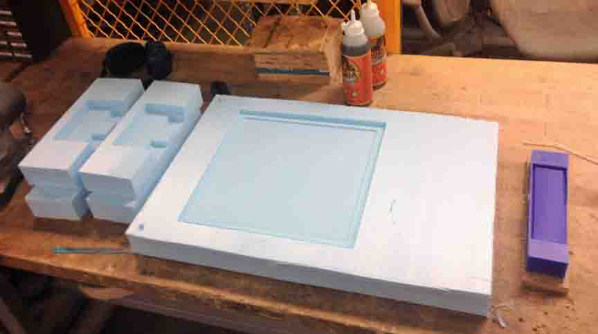
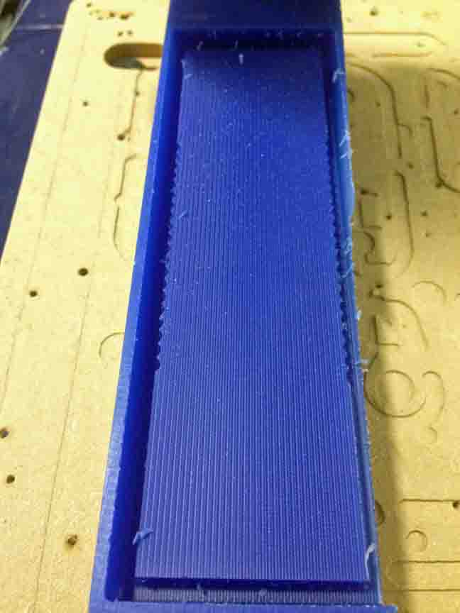
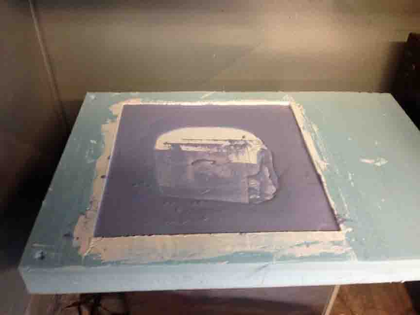
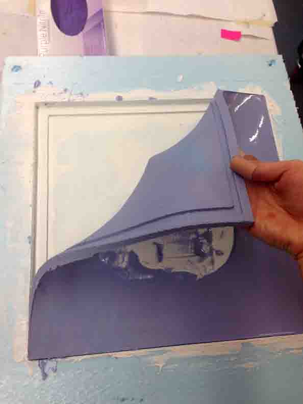
I do not trust press fit acrylic to be completely water tight, even with cement, so I've chosen a process which can fabricate uniform solid forms. Vaccuum Form plastic is rapidly shaped, and translucent to match the outer shell. I do not trust press fit acrylic to be completely water tight, even with cement, so I've chosen a process which can fabricate uniform solid forms. Vacuum Form plastic is rapidly shaped, and translucent to match the outer shell. Reminiscent of composite mold-making from Week 9, I started with blue foam. I made a quick, modular 'mold' to test the limits of dimensions that can feasibly be vacuum formed. On Shopbot, I milled (x4) 10"x10" squares from 2" foam. They can be stacked to 2", 4", 6", 8" and wrapped in parchment (for smooth release) for some iterative testing. 2D cuts require V-Carve for tool pathing. I cut another square from board stock to give the top of the cube some rigidity and shielding from the heat.
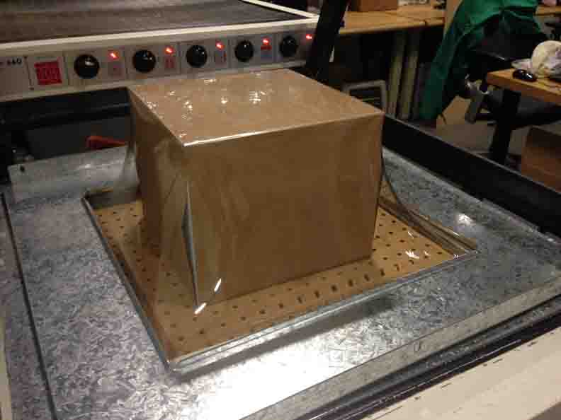
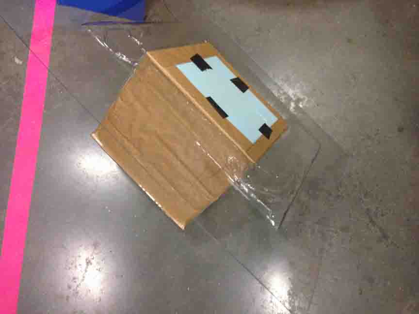
Notes from Experience: Foam crushes once it gets too hot. It was a huge struggle with a chisel (unsafe!) to release the mold from my form. You will have a better time releasing you mold if you use a solid material like wood or acrylic to build your mold. Bonus, make you cube slightly 'conically- tapered' so it slides out. Double-bonus, make a 'collapsible' cube. **UPDATE** Second iteration, using MDF (medium density fiberboard) to create the collapsible box! - It works like a charm :)
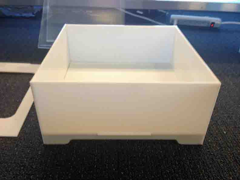
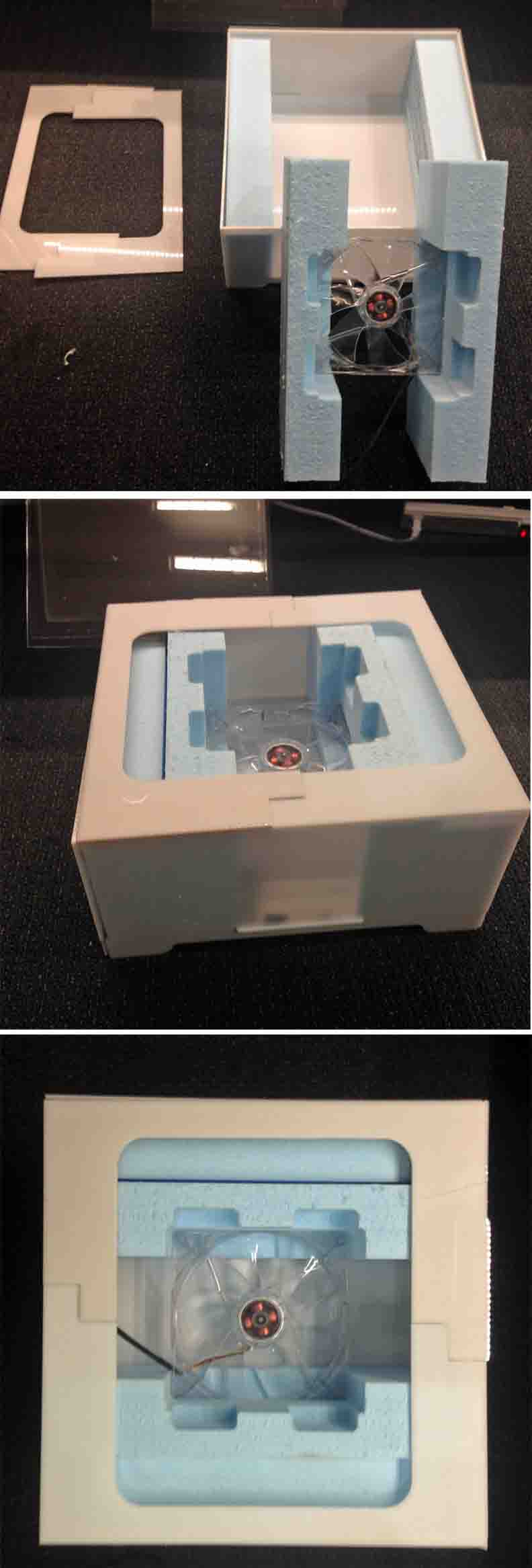
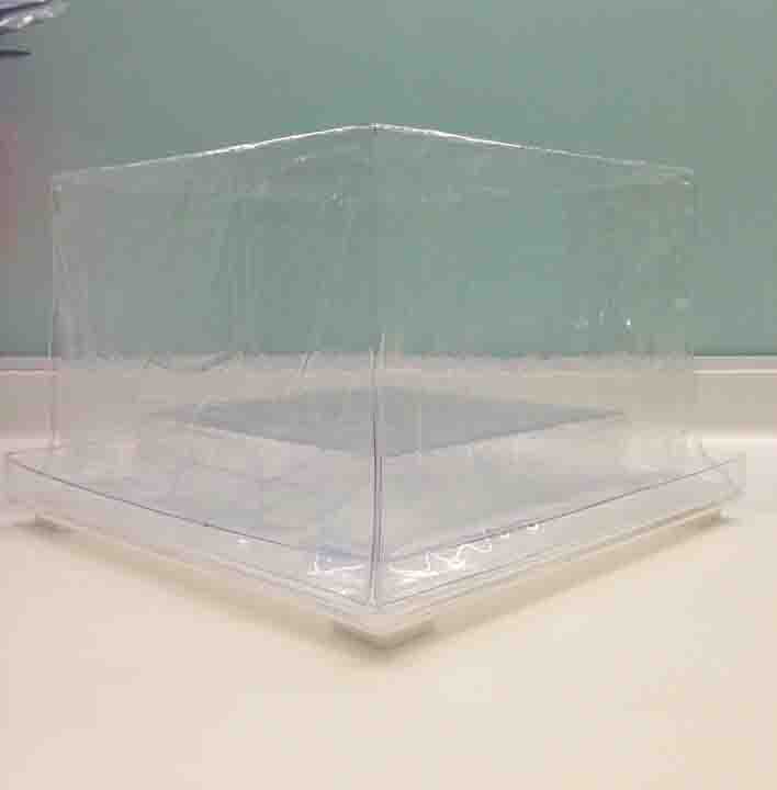
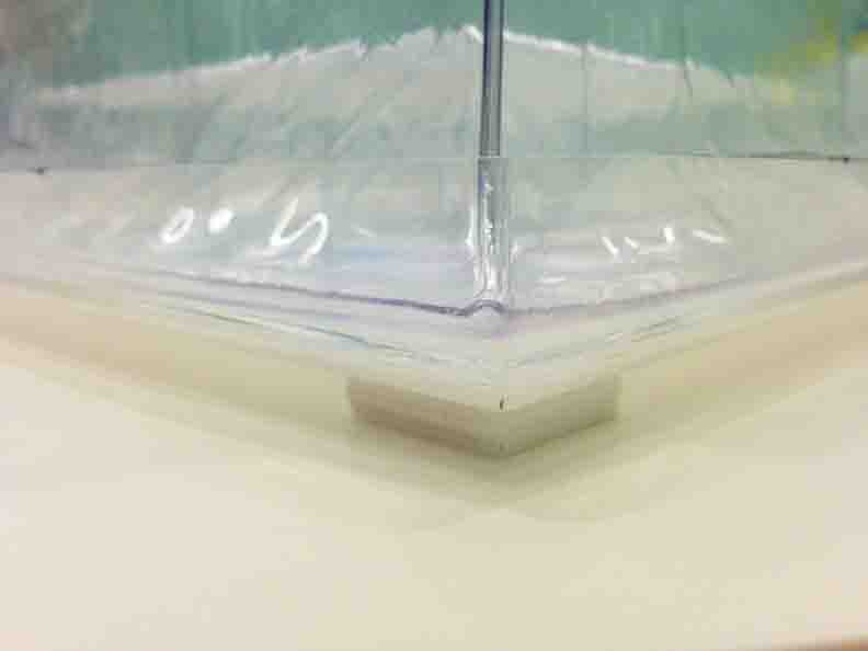
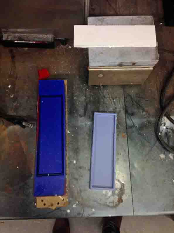
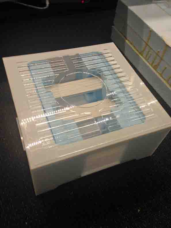
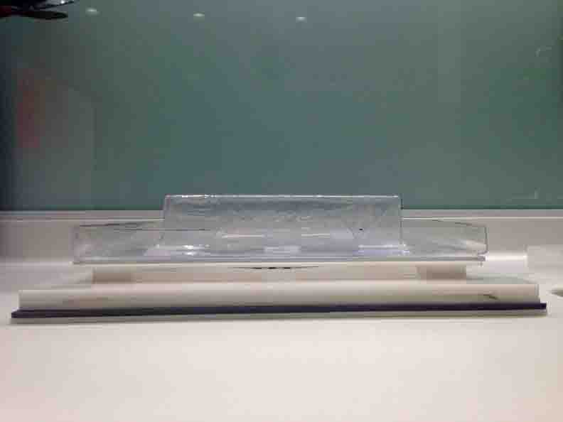
Here is the final rendition. Cut down with band saw and assembled with tray, cover and interior display stage - the vacuum form plastic is combined with an earlier laser cut base with feet. Once filled, the water also acts as a air-tight, vacuum seal which could be released with a rubber plug - so good job inner containment/humidity chamber!
Looks great!
Even more CNC milling can be found in the Molding and Casting section below.
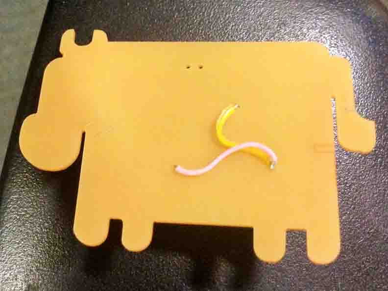
Electronic Inputs and Networking
Continuing on the networking week, I added the temperature reading function to my cow. Requiring a serial bus to transmit from a node as well as retrieve proved to be a huge step for my I2C code to be able to handle. Still working on it.
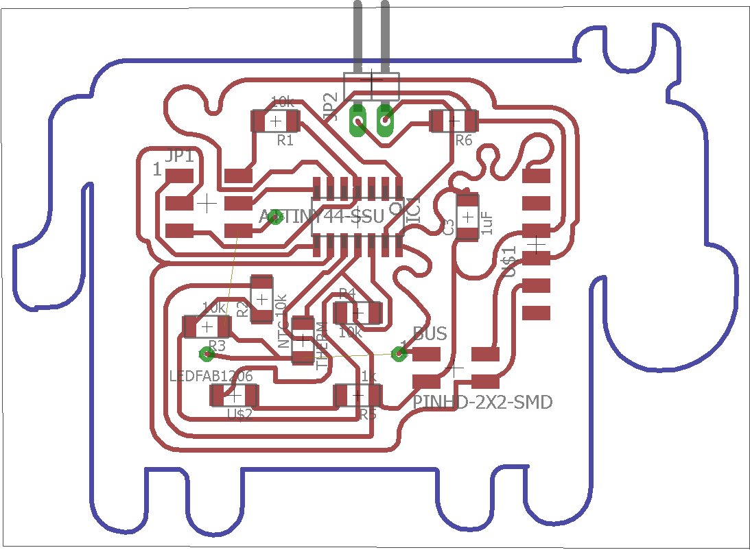
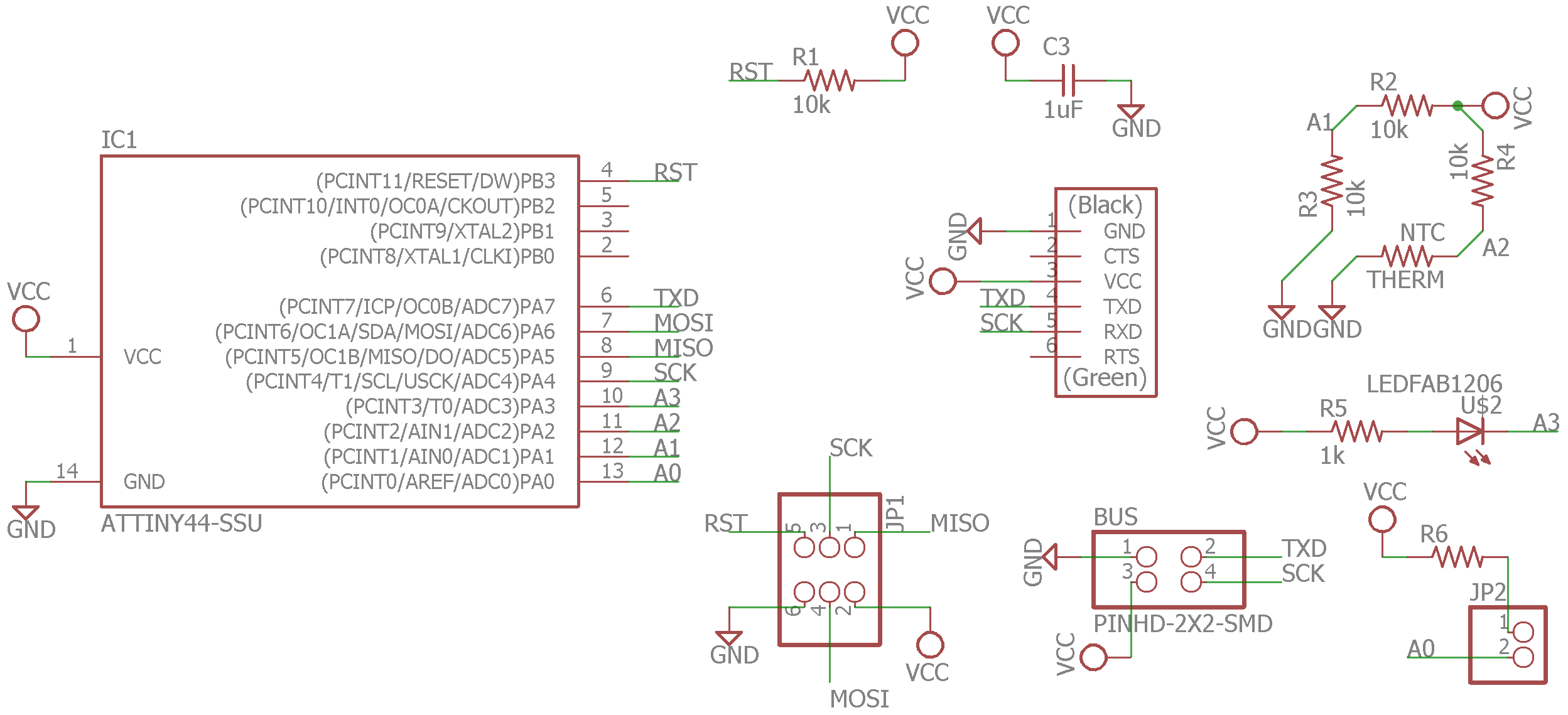
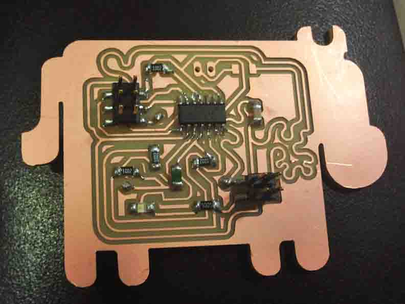
I wrote my own code for this process. Based off the synchronous Arduino - environment serial bus there is one MAJOR limitation I discovered after many dozens of hours of coding. If I want my boards to be able to have duel-direction communication (i.e. slaves can transmit as well as recieve), only TWO boards can be supported. One Master and one slave. If you add any more, the second slave's serial pin holds down the line and prevents any other communication. (This can be solved in C, with Neil's code - see Week 12 - but for now we continue with 2 cows.)
Master Cow Temp Code:
const int cycle_delay = 1; //ms
int therm1_pin = 2;
int therm2_pin = 1;
SoftwareSerial mySerial(7, 4); // RX, TX
void setup() {
mySerial.begin(9600);
pinMode(3, OUTPUT);
pinMode(therm1_pin,INPUT);
pinMode(therm2_pin,INPUT);
}
void requestTemp(int id) {
mySerial.write(1); mySerial.write(2); mySerial.write(3); mySerial.write(4);
mySerial.write(id); //address the node
mySerial.write(8); //led command, "blue_duty"
int temp1 = 0;
while (mySerial.available() > 0) {
temp1 = mySerial.read();
mySerial.println("M002");
mySerial.println(temp1);
}
delay(200);
}
void loop() {
digitalWrite(3, LOW); // turn the LED on (HIGH is the voltage level)
delay(200); // wait for a second
digitalWrite(3, HIGH);
delay(200); // wait for a second
int Mtemp2 = analogRead(2);
int Mtemp1 = analogRead(1);
mySerial.println("M001");
mySerial.println(Mtemp1-Mtemp2);
requestTemp(2);
//requestTemp(2);
delay(cycle_delay);
}
Slave Cow Temp Code:
const int node_id = 2;
int b1,b2=0,b3=0,b4=0; //framing bits
int id_read = 0;
SoftwareSerial mySerial(4, 7); // RX, TX
int blue_pin = 3;
int therm1_pin = 2;
int therm2_pin = 1;
int blue_duty = 0; //duty cycle of leg pins of 255
int therm_duty = 0;
void setup(){
mySerial.begin(9600);
pinMode(blue_pin,OUTPUT); //set up led pins as outputs
pinMode(therm1_pin,INPUT);
pinMode(therm2_pin,INPUT);
}
void read_duties(){
while(mySerial.available() == 0);
id_read = mySerial.read(); //keep reading till something, not 0
if (id_read == node_id){
while(mySerial.available() == 0);
therm_duty = mySerial.read();
}
}
void loop(){
if(mySerial.available() != 0){
b1=b2; b2=b3; b3=b4;
b4 = mySerial.read();
if(b1==1 && b2==2 && b3==3 && b4==4){
read_duties();
if(therm_duty == 8){
int temp2 = analogRead(2);
int temp1 = analogRead(1);
mySerial.write(temp1-temp2);
digitalWrite(blue_pin,LOW);
delay (500);
digitalWrite(blue_pin,HIGH);
delay (500);
id_read = 0;
therm_duty = 0;
b1 = b2 = b3 = b4 = 0;
}
}
}
}
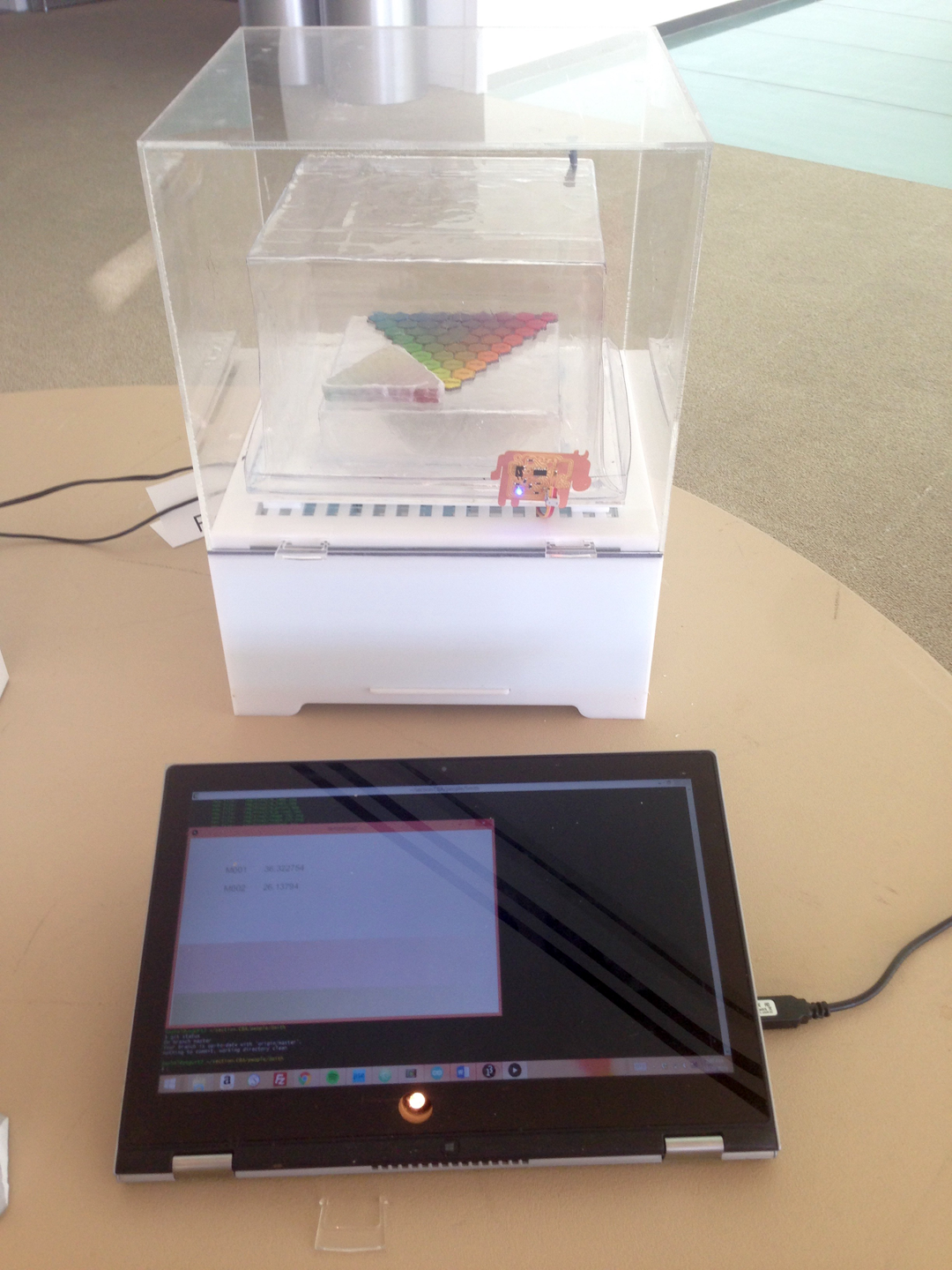
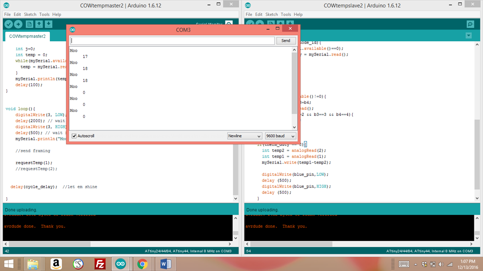
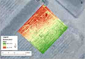
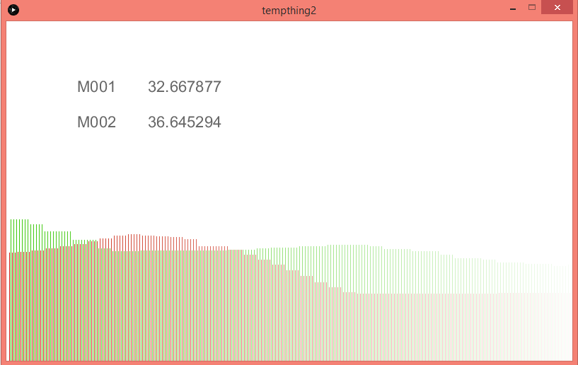
Here you can see them working from the serial port!! In the future I hope to be able to add more cow, (either through serial bus or through charlieplexing) so I can input data more like a heat map - to really take advantage of the networking functionality. For this I would start with Neil's Asynchronous C-code. While temperature is not a very time intensive reading, there would still be no way to support that many boards with the current code. In the Interface programming section, I describe how I create an application to read and convert these values.
This would be a cool next step:
Electronic Output and Power Supply
The next step is to create a heating element to heat a ~cubic foot of air to 37.5 degrees Celsius. To ensure we have head room to regulate temperature it is good to be able to reach target temperature when ON only 10% of the time. This will require me to use mains power for the first time. There are many options for heating, including small heating peltries, connecting hair dryers via a solid state relay. I chose nichrome wire (maybe foolishly) because it is truly a self-made heating element, and much like Street Bio's HTGAA/iGEM project: see Biota Beats page . There is expanded control in gauge and thus resistance.
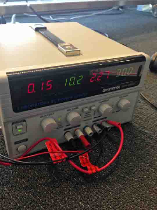
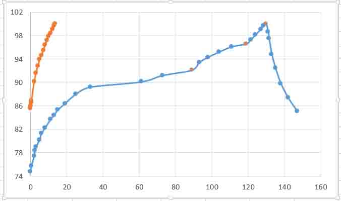
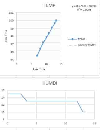
I start by testing my wire with a lab power supply. A length of ~4" of 28 gauge wire is 12.8 Ohms. At 30V / 2.3 A it can reach 37.5 degrees (100 Fahrenheit) in around 16-20 minutes. However, in this set up I am also interested in powering a fan rated max at 12 V / 1A. I decide to find a shared power source at 12 V. In parallel, if my wire takes care a majority of the amperage with its calculated resistance, the fan should be fine.
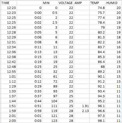
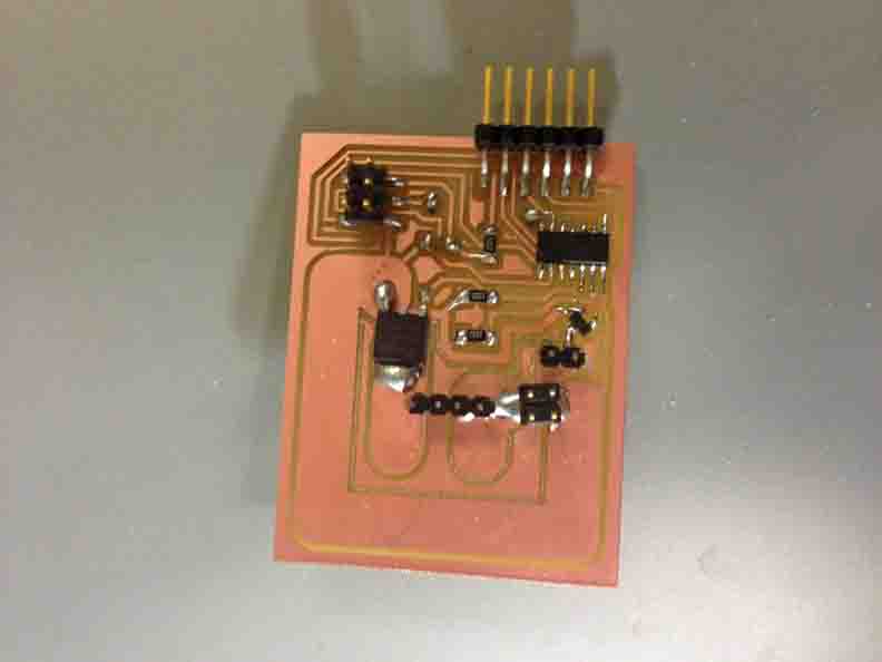
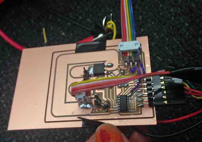
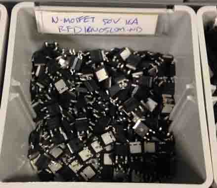
Now that I know my power needs, I have designed an output circuit to manage these different amperages, with N-Mosfet switches to control the turning on an off of power. I plan to have an FTDI connection, so it can receive a signal via the serial from my processing code of the temperature sensors. My circuit and code are here.
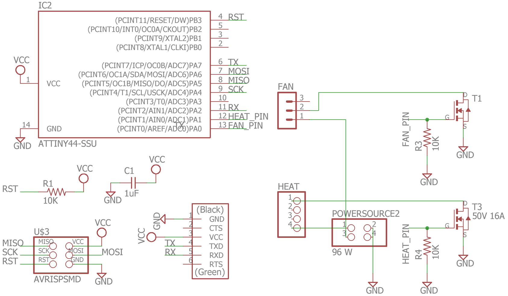
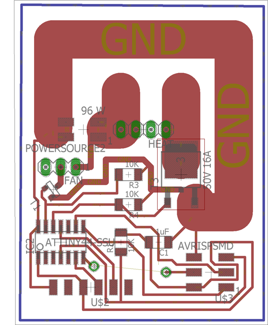
Two good websites to make you feel more comfortable designing for mains power for the first time are these: high power control wiring and for trace width estimation (notice my veerrry conservative thick traces).
Heat and Fan Board Code, to interact with my Processing code:
SoftwareSerial mySerial(7, 2); // RX, TX
char val='x';
void setup() { // put your setup code here, to run once:
mySerial.begin(9600);
//pinMode(0, OUTPUT);
//pinMode(1, OUTPUT);
pinMode(10, OUTPUT);
digitalWrite(10,LOW);
}
void loop() {
mySerial.println("woot");
if (mySerial.available()>0)
{
val = mySerial.read();
}
if (val == '1') // too low
{
mySerial.println("below");
} else if (val = '0') // too high
{
mySerial.println("above");
} else {
mySerial.println("undef");
}
delay(100);
}
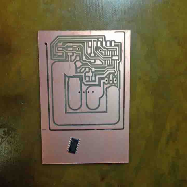
Sadly, DISASTER STRIKES! My board fried in a quite noticeable flame and puff of smoke. Specifically the Fan's N-Mosfet to G pin. I have a strong feeling this is because my wire resistance was too high, driving too large a portion of the shared current through the fan. I have remade the board a second time but have not got the guts to try again yet. SCARY!
In the future I wish I could have more guidance on high power boards.
My board's smoldering remains.
Molding and Casting
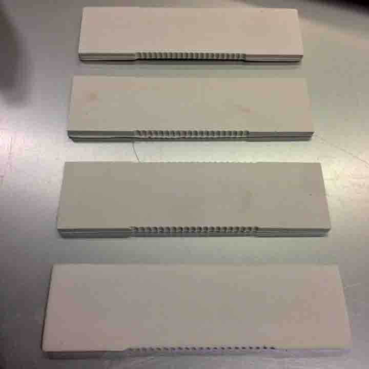
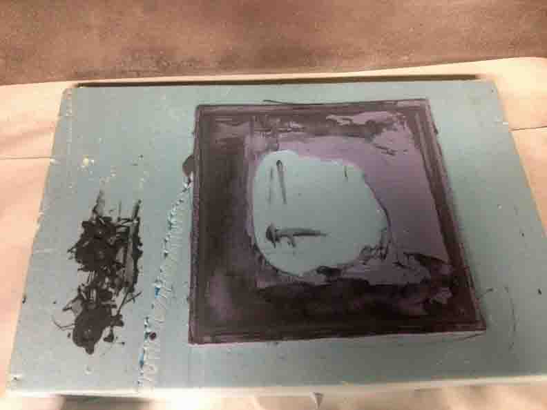
The main use of molding was to create the ceramic heat dissipaters that the wire is wrapped around - the circuitry called for me to put at least two in parallel, so it was a go fit with the ability to repetitively cast. The notches are to guide the (uninsulated) nichrome wire winding, to ensure it does not short on itself - I only needed about 7" of wire in the end, but it still did its job! (pic, bottom right: placement inside the incubator, resting on custom fom inserts.)
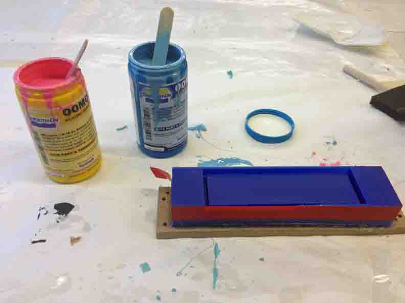
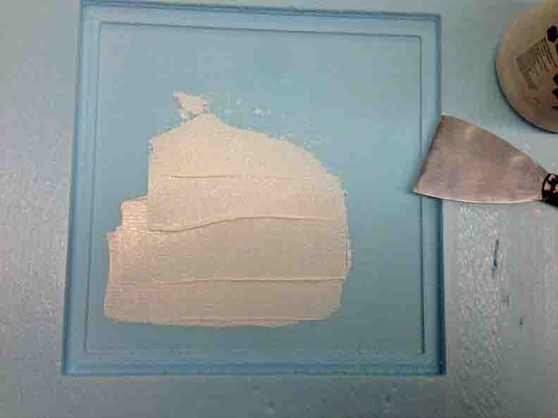
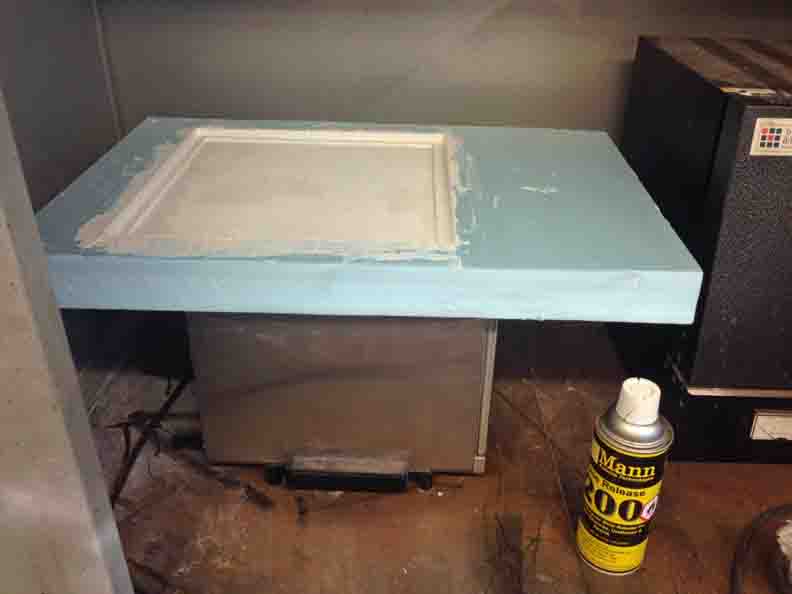
But wait, there's more!! I was busy molding a number of essential parts - rubber gasket to the outer containment unit - I milled on the desktop ShotBot, out of foam. This took an extra step of gesso-ing the foams surface with two coats, and then LOTs of mold release. A suggestion from Grace, who used this strategy in her weekly work. Comes out nicely. .
In these pictures, I am actually forming an oomoo cast in an oomoo mold. I colored them differently so you can differentiate. This is because, while I tried other materials like Semi-Semi-Rigid Plastic, oomoo had the best soft consistency for the gasket in the end.
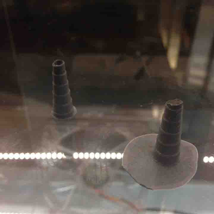
Also molded plug for the inner containment unit's vacuum seal. They look funky.
Embedded Programming and Interface Design
See Week 11 - for the interface design of incubator-cows telling temp!
Assembly
(Last but not least) 3D Printing and Bacteria!
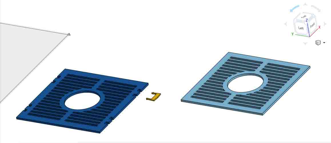
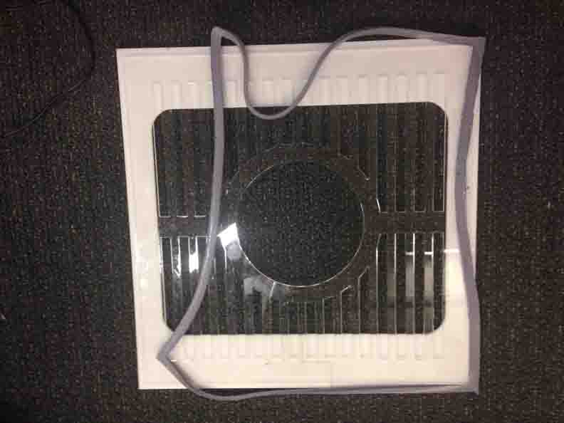
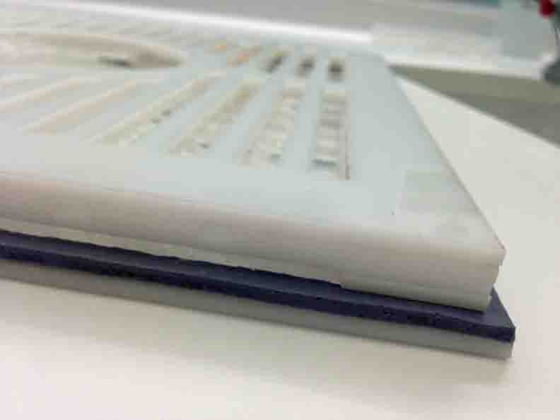
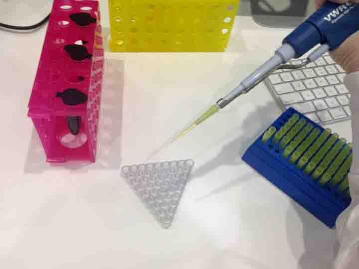
Printed on the Stratasys Connex in Vero Clear. Wells and Lid. Technically, this shape could be milled, but it would not be so pretty and translucent without polishing. The support material is semi-water soluble. I usually do 1-2 repeats of power washing with water and soaking (like below) in an HCL solution. It is especially important to wash well afterwards so you don't kill you bacteria!
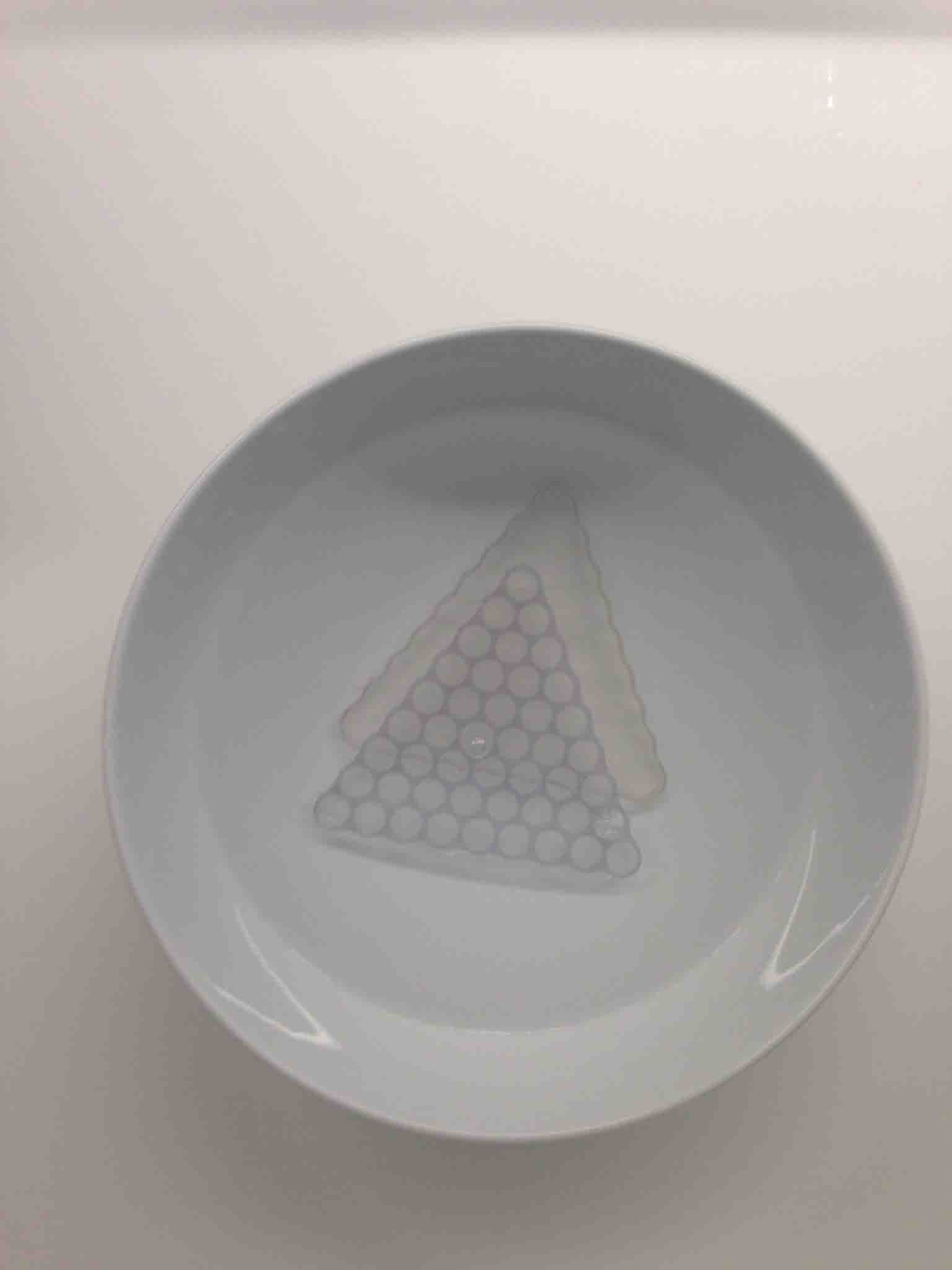
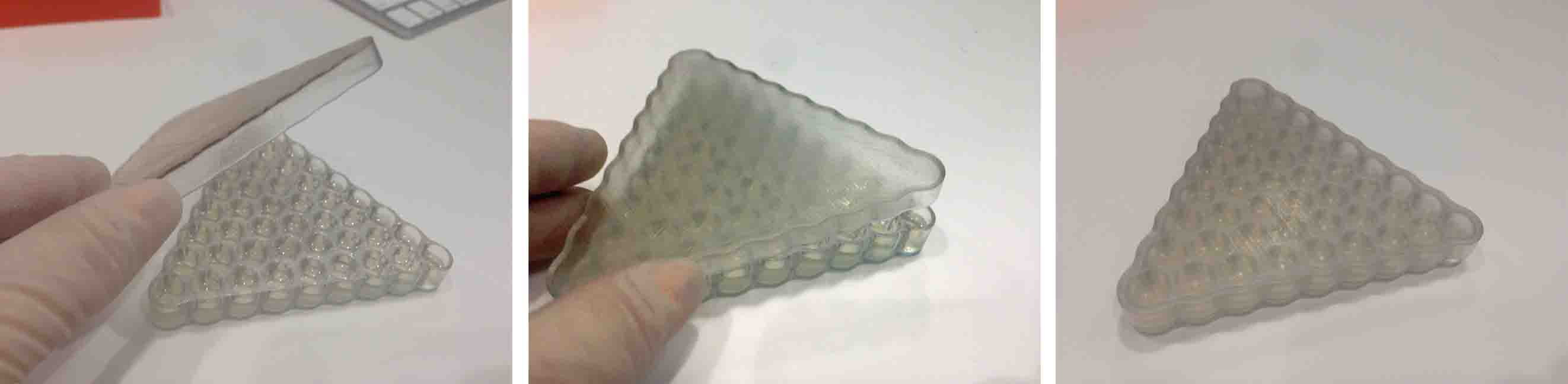
The test I've created involves color matching bacteria to the Stratasys color 3D printing capabilities - just a little way to brag that bacteria are just as cool as these hundred thousand dollar behemoths. To set up a color triangle, I'll need a 9X9X9 cell triangle. Lab standard 96 well plates will not do, so let's 3D print non-traditional lab ware. Below (right) is the expected result for the #D printed dish. We will see in 16 hours!
I present: Living Display