WEEK 12: _ design and build a wired or wireless network connecting at least two processors.
Serial Communication via a Bus
Serial communication is a powerful tool to pick up - for some of the sensing applications for my final (or future) project I feel that both serial buses and charlieplexing can build up complexity to do some interesting arrays of things. For instance, what if each board had three thermistors (6 pins requires) and was able to triangulate/vectorize a direction from which heat is coming from. Then, if there were multiple of these boards in serial they could affect and interface or the movement of their collective object, like a dilating pine cones.
Output Board Design and Fabrication
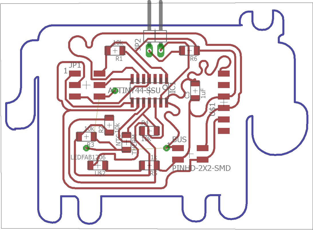
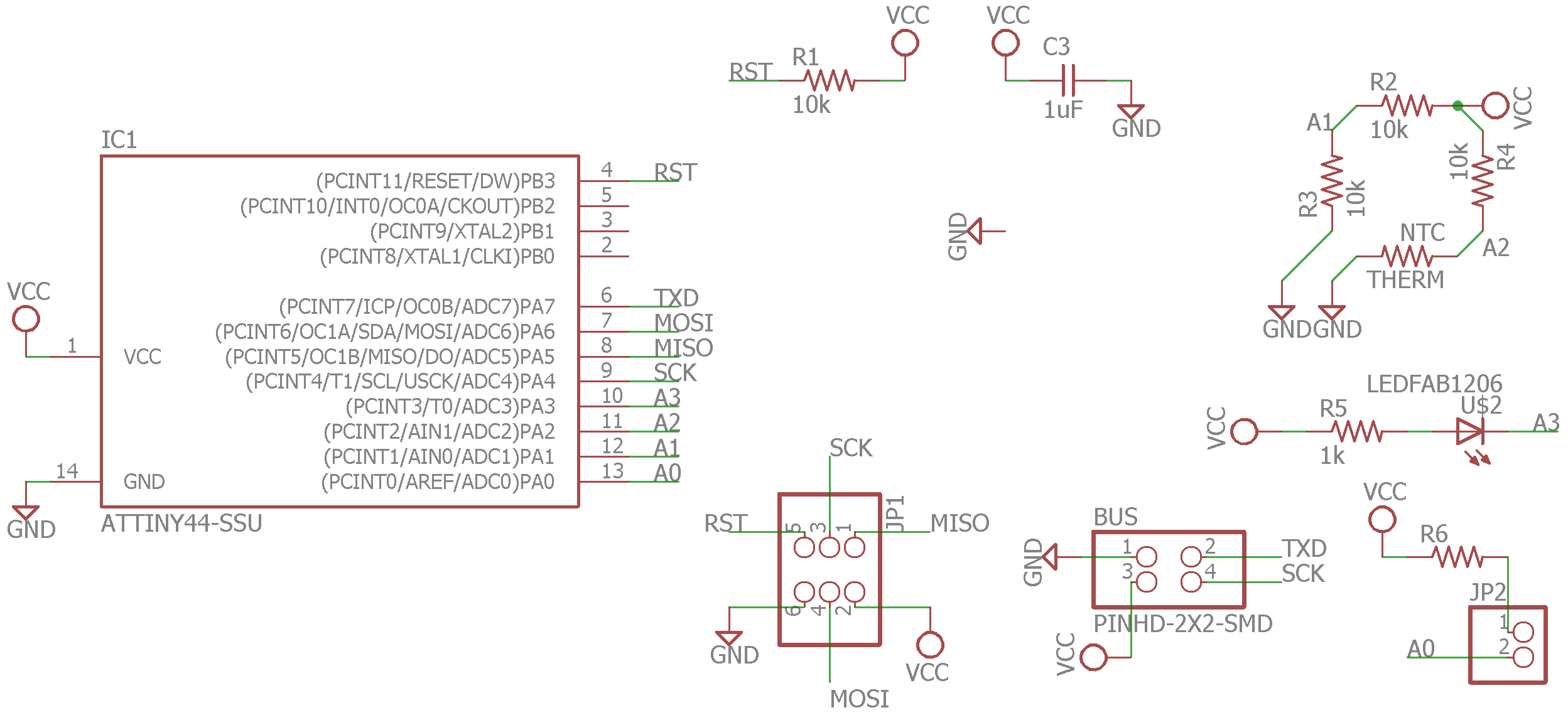
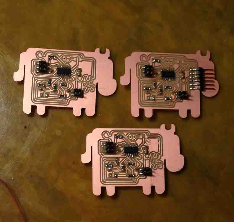
I designed the boards based of Neil's Asynchronous Busing boards. Using an ATTiny44 instead of an ATTiny45, I was able to spare several more pins for new features. I added an INPUT (2 pins) of a temperature sensor, which uses a grouping of 3 resistors and one thermistor. Also, I've left traces for an OUTPUT pin leading to a small heating element that can be powered off 5 V.
The bridge node has an FTDI cable to interface with the computer, and the 4-pin header serial bus connection. You will be connecting subsequent node boards to a Transmit (TX) and Receive (RX) signal, and well as VCC and GND. Four wires total.
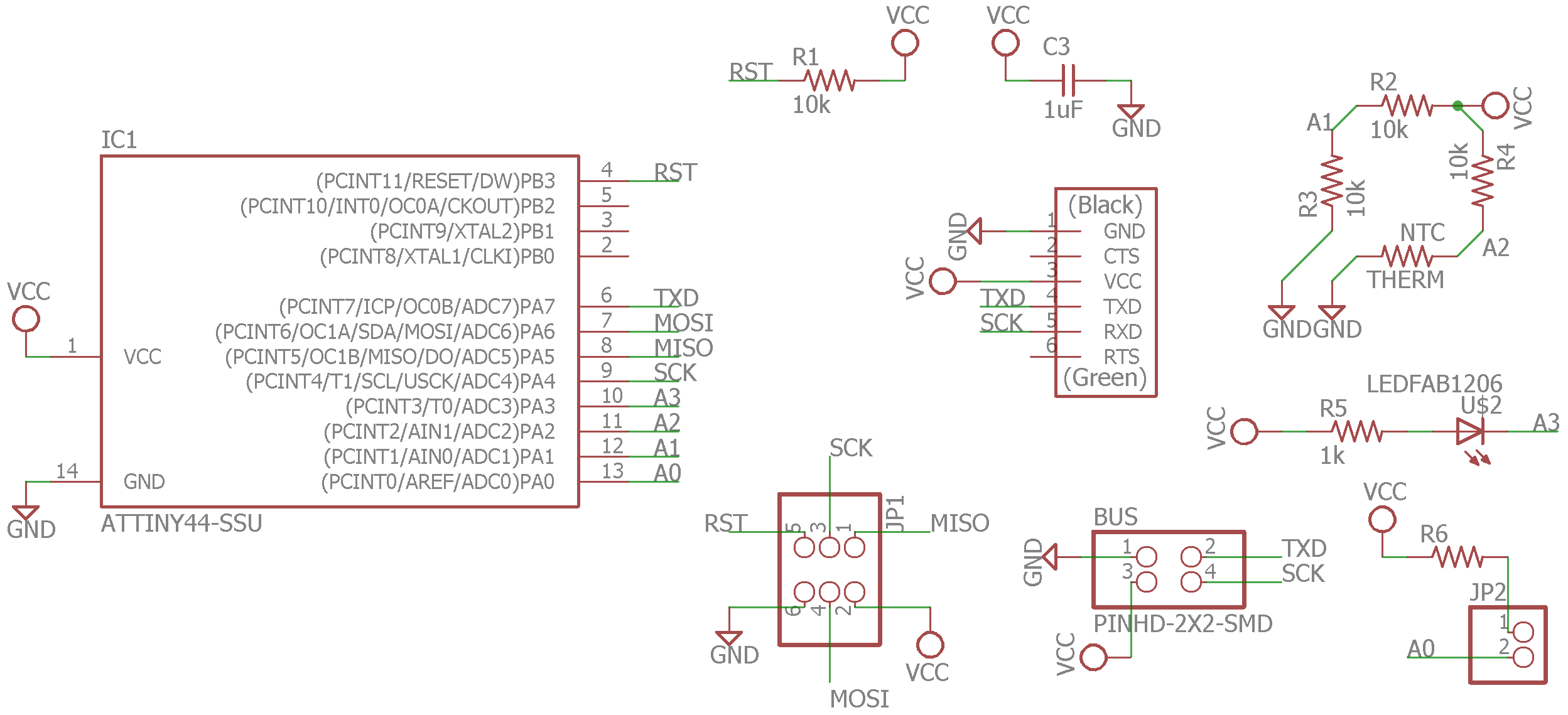
The slave nodes are identical to the bridge in wiring. They just lack an FTDI cable because they will be connected to everything they need via the serial bus!
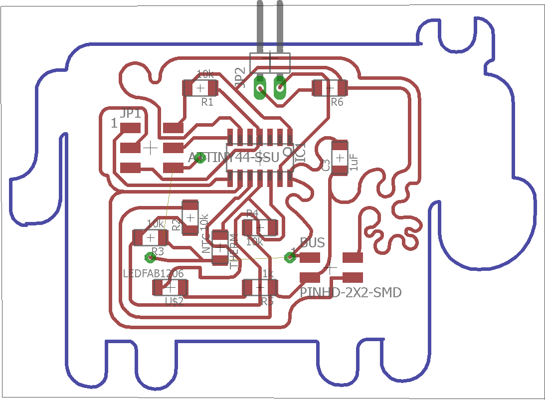
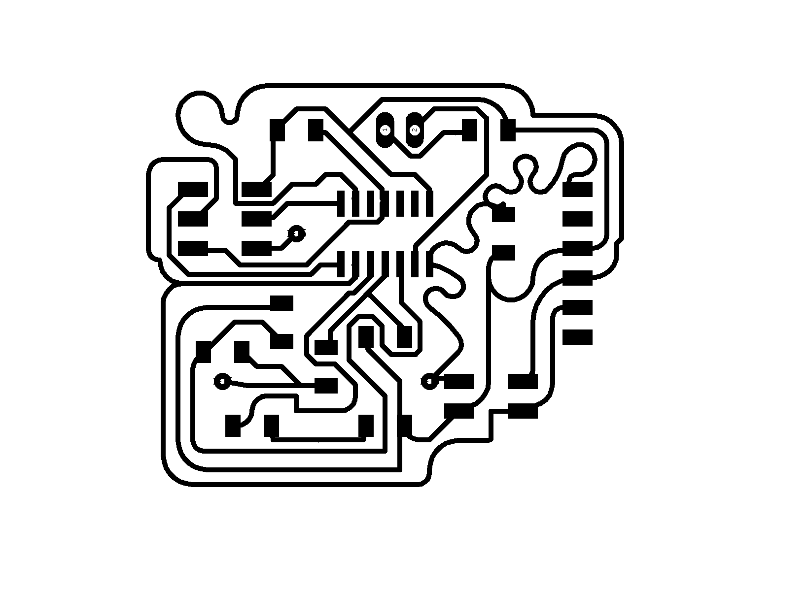
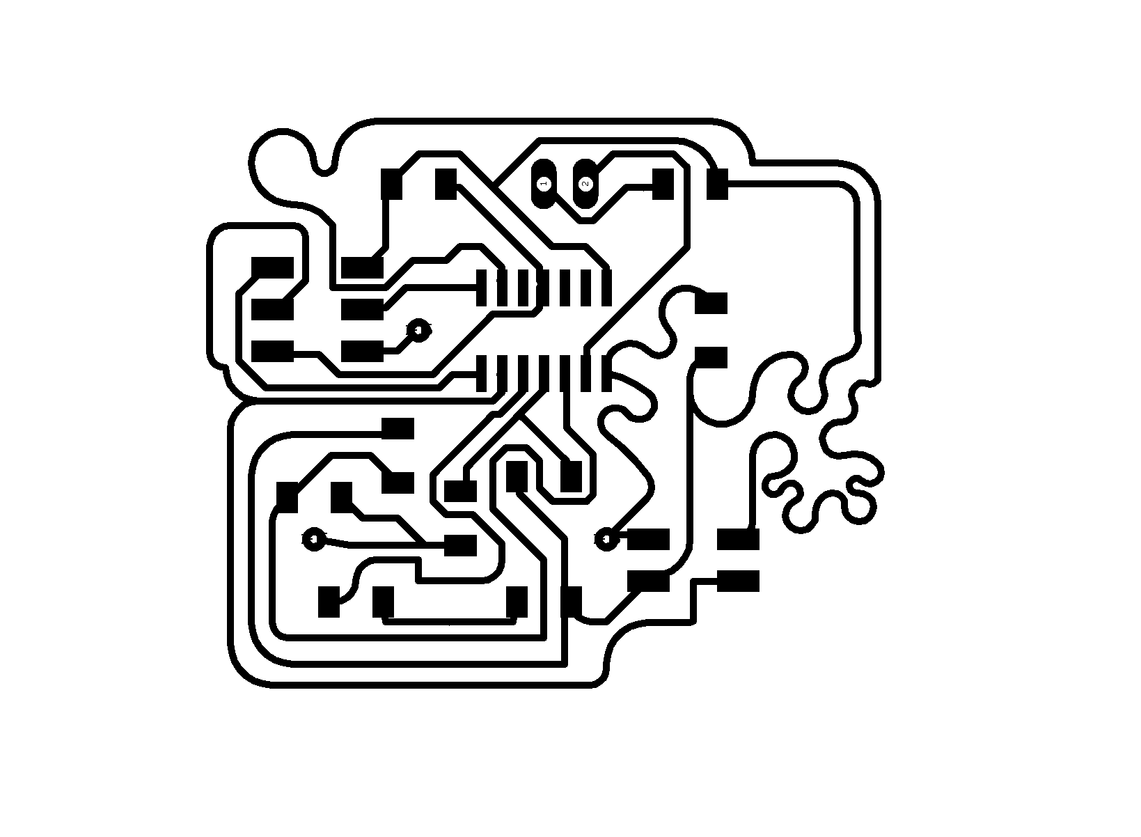
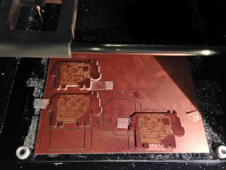
Here are all the trace, incluing vias to route GND with jumpers on the back side of the board.


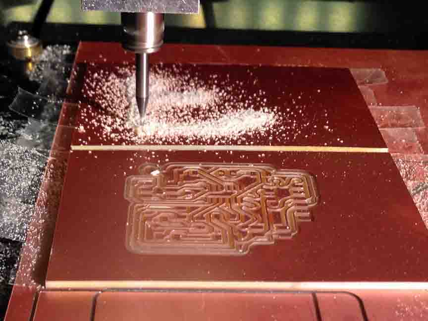
Milling and stuffing.
Connecting a Bus
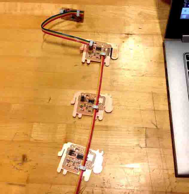
This is the configuration in which a bus should be configured.
However, you will need to plug connections in in a certain sequence in order to program. Furthermore, I chose to share the programmer's SCK line with RX, so your master cow must be flashed clean to begin programming other nodes or else it may be pulling up or down the SCK line. Order for programming:
0: Connect FTDI cable, programmer cable (6-Pin) and serial bus cable (4-Pin) to Bridge Cow
1: Flash Bridge Node, if previously programmed
2: Connect programmer cable to Node Cow (n)
3: Link Node Cow (n) to the serial bus coming from Bridge Cow
4: Program Node Cow (n) with nodebus.program
5: Unlink Node Cow (n) completely
6: Repeat Steps 2-5 for all Node Cows, seperately
7: Connect programmer cable back to Bridge Cow
8: Program Bridge Cow with bridgebus.program
9: Connect in the working configuration shown above
Programming a Synchronous Bus
I wrote code in arduino to frame data coming down the serial bus. Based generally on the code for Sam's Disko Kayak LEDs, 2 years prior, I have the Master Cow calling all the shots. In a loop, Master Cow send the recognized framing message "1", "2", "3", "4". Then it will send a node ID, 1 or 2, and then it will send a number that is representative of a function for the Slave Cows, like flashing an LED.
I slowed down the loop with large delays between each line of code, so in the video you can actually see when the Master Cow initiates its loop (LED on) and the when each slave cow receives a message in order. Success!
Here is the Master Cow code: :
const int num_nodes = 2;
const int cycle_delay = 10; //ms
SoftwareSerial mySerial(7, 4); // RX, TX
void setup(){
mySerial.begin(9600);
pinMode(3, OUTPUT);
}
void loop(){
digitalWrite(3, LOW); // turn the LED on (HIGH is the voltage level)
delay(2000); // wait for a second
digitalWrite(3, HIGH);
delay(500); // wait for a second
mySerial.println("Moo");
for(int i=0; i
mySerial.write(1);
mySerial.write(2);
mySerial.write(3);
mySerial.write(4);
mySerial.write(i+1); //address the node
mySerial.write(8);
}
delay(cycle_delay); //let em shine
}
And the Slave Cow code. Remember to change the node ID from one programming to the next:
const int node_id = 2;
int b1,b2=0,b3=0,b4=0; //framing bits
int id_read = 0;
SoftwareSerial mySerial(4, 7); // RX, TX
int blue_pin = 3;
int blue_duty = 0; //duty cycle of leg pins of 255
void setup(){
mySerial.begin(9600);
pinMode(blue_pin,OUTPUT); //set up led pins as outputs
}
void read_duties(){
while(mySerial.available()==0);
id_read = mySerial.read(); //keep reading till something, not 0
if (id_read == node_id){
while(mySerial.available()==0);
blue_duty = mySerial.read();
}
}
void loop(){
if(blue_duty == 8){
digitalWrite(blue_pin,HIGH);
delay (500);
digitalWrite(blue_pin,LOW);
delay (500);
}
else{
digitalWrite(blue_pin,LOW);
delay (500);
}
if(mySerial.available()!=0){
b1=b2; b2=b3; b3=b4;
b4 = mySerial.read();
if(b1==1 && b2==2 && b3==3 && b4==4){
read_duties();
}
}
}
Programming an Asynchronous Bus
For this process, I use the code the Neil provides. It differs in the fact that all the cows are 'slave' cows or nodes to the serial on the computer. The 'bridge' now gets the exact same code as all of the rest of the nodes, it is not definitively the 'master'. The advantage of this code is that for any given moment after a node have been called, its Transmit and Receive pins are switched and it becomes the transmitter (hence it's ability to write "node#" in the serial port). The code can be found here - the only edit I’ve made to it is a change to an ATTiny44:
_ > hello.bus.45.c
_ > hello.bus.45.make
My next step is to be able to integrate a thermistor reading into this loop, so it prints an analouge reading with its node #.