WEEK 4: _ draw the hello-world board, add button and LED, and make it.
Electronics Design in Eagle
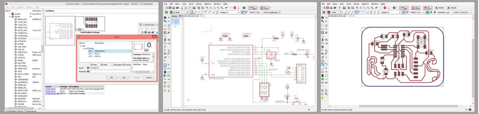
This was the week of doing things the hard way before figuring out that, indeed, there was an easy way - possibly a hazing process into the not-completely-intuitive world of Eagle. All round it made for a good learning process I can share with you, and a more creative looking output. The best way to start orienting yourself with Eagle, is to know that there are three view modes you can reference simultaneously;
_ [1] the command window, to view your Libraries and files,
_ [2] your schematic view, to place components and relationships, and
_ [3] the board, to compose your physical parts and traces. For now, only worry about them in that order.
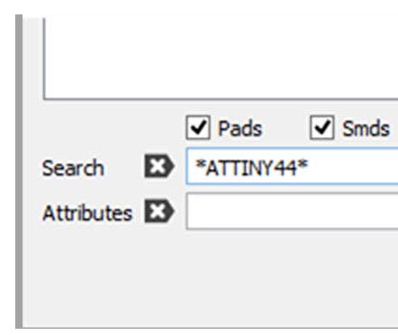
The first challenge in my burgeoning relationship with Eagle is to import a library and 'ADD' a component to my schematic. So, LESSON 1, for command window/library, is USE WILDCARDS(*) BEFORE AND AFTER PART NAME WHEN SEARCHING! (See ATTINY44 search below, right.)Make a habit of it - the search mode is very picky, unlike a web browser search like google. I hope this save some future frustration.
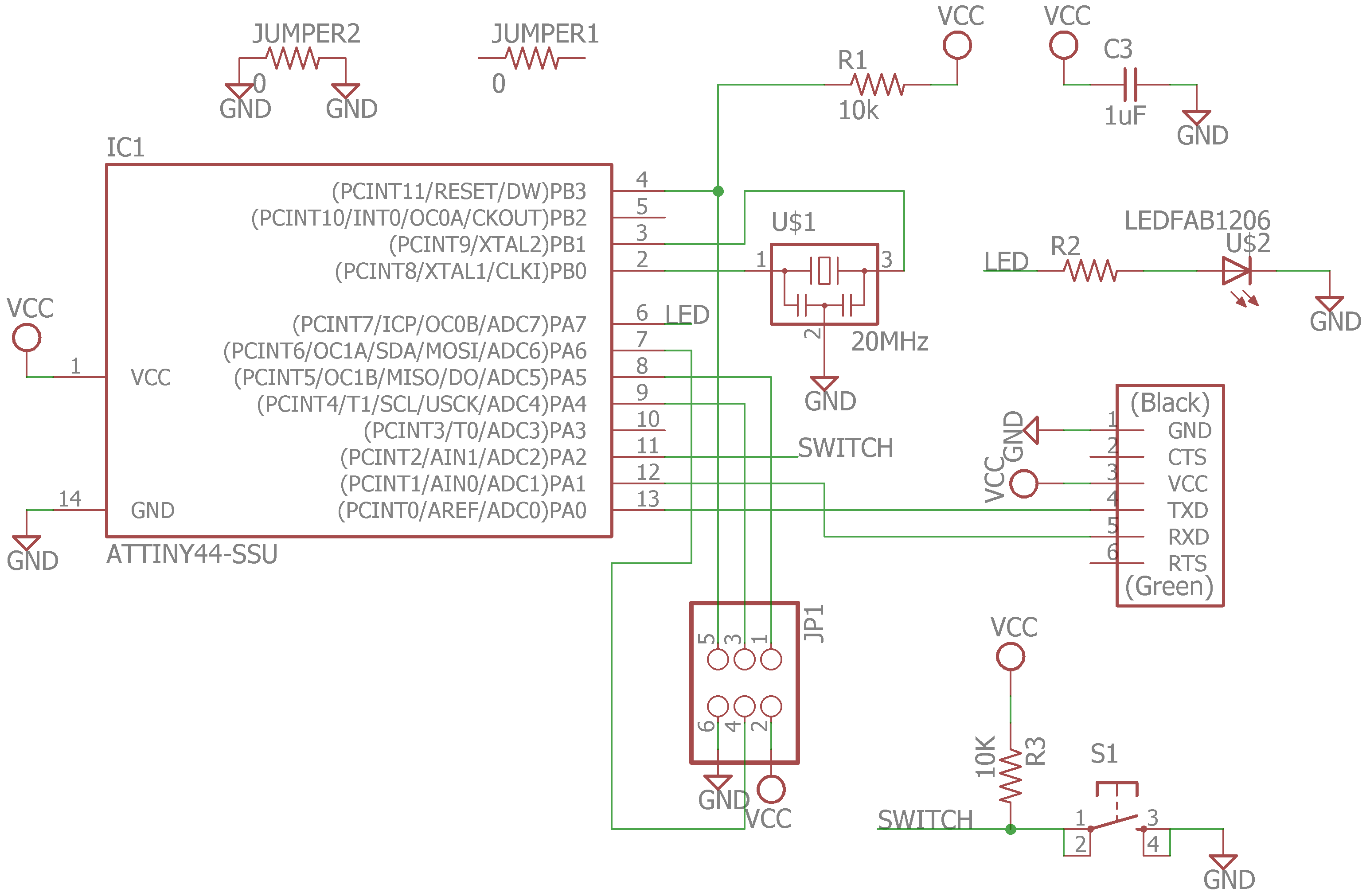
In the schematic view, I learned to place my parts, including an LED and SWITCH on two empty pins. Using the point-and-click method, wiring is not always accurate. In order to ensure that your wires are actually connected where you think they are, use the 'MOVE' function to jiggle them around and see if the wires come with. Neil suggests.... use the terminal commands to connect, I'm not that abstract yet. However, I soon learned there is an easier way yet;
What I did: connect all wires literally, as though they were trace.
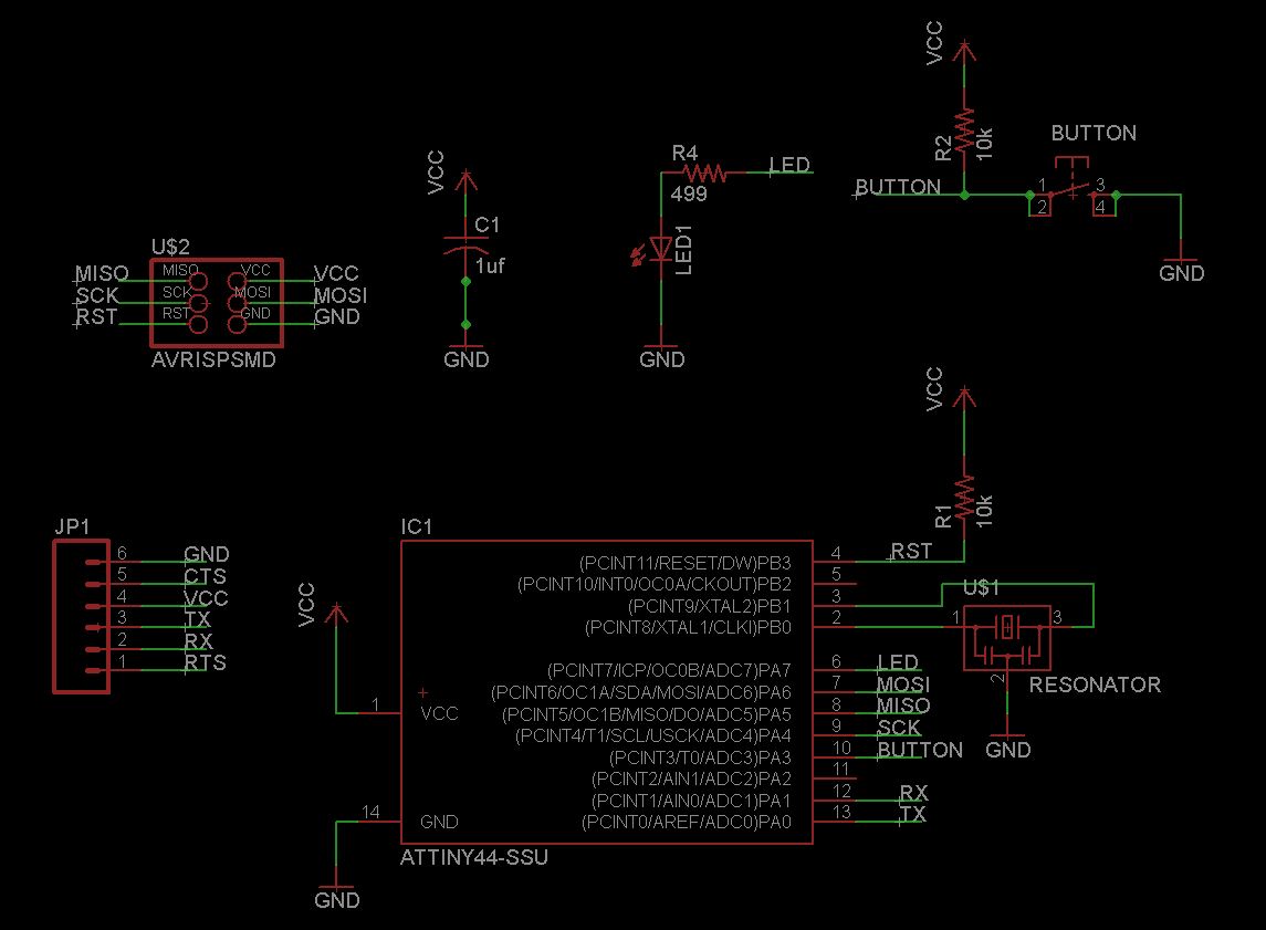
What pros do: allow components to exist in space, and reference connections with assigning name values to wires; Result: easier reading of your own schematic. (correct example credit: Ben Jennette, htmaa2014)
In board view I then needed to route all your traces in one layer. The yellow lines act as guides to what needs to connect, and the command 'RATSNEST' will optimize each time you've moved your parts around. Remember, if you need to remove a trace, use the 'RIP UP" command as opposed to 'DELETE'.
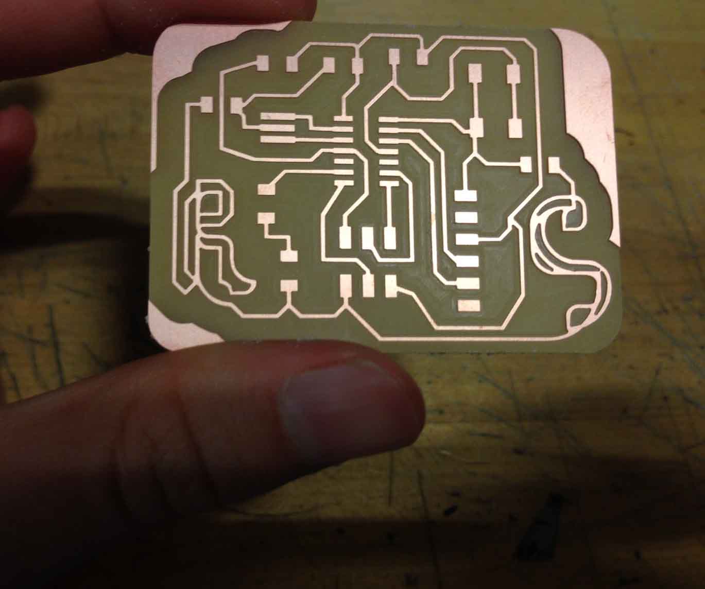
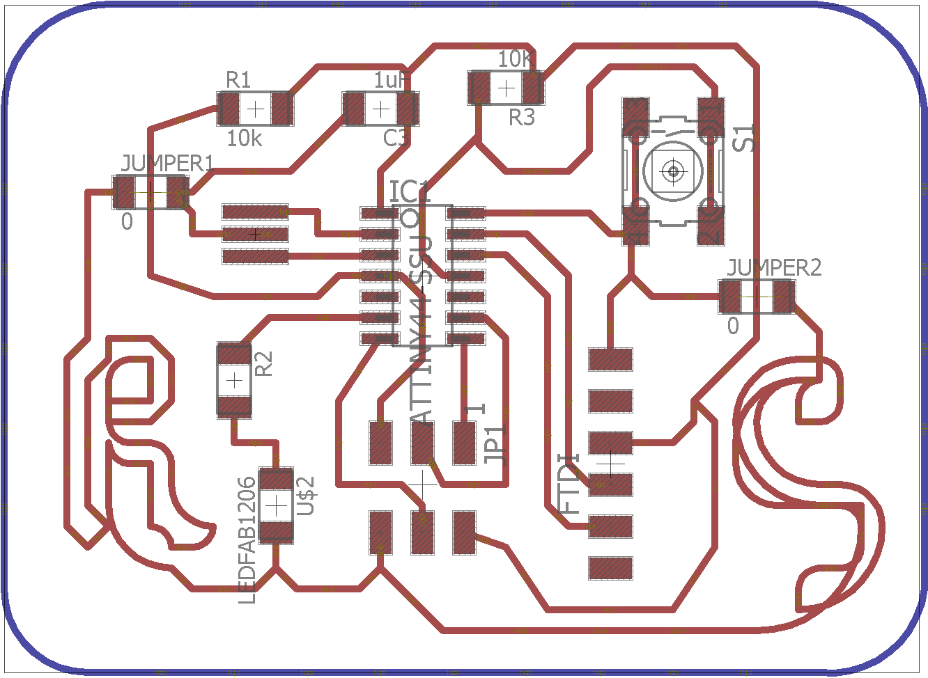
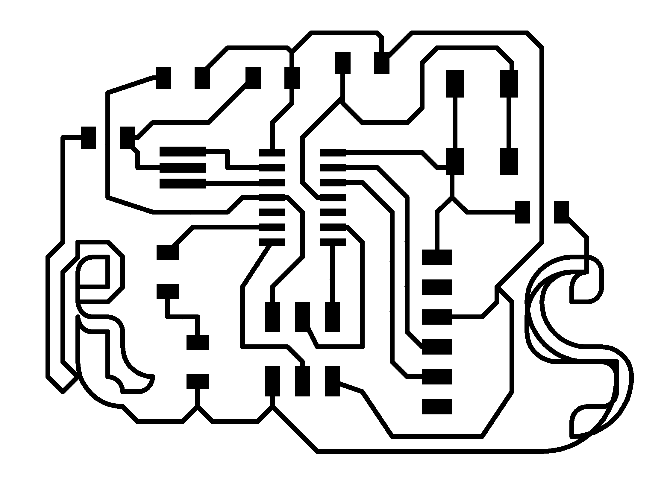
What I did: tracing by hand, you get a very zen puzzle as well as some creative freedom. I managed to connect my board, but only using two 'jumper' (i.e. 0 ohm resistors) to get my ground wires connected. Extra soldering, and not the most compact circuit - but at least I got to doodle in my initials.
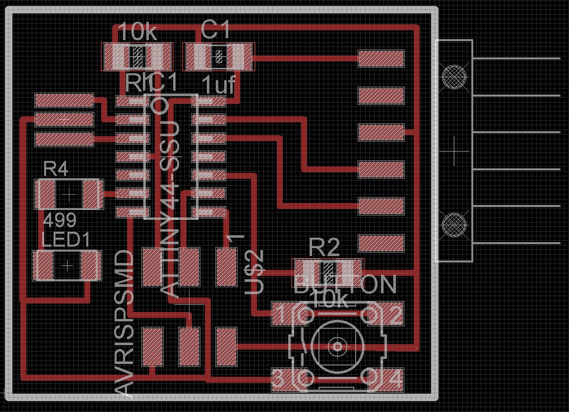
What pros do: this handy command called 'AUTOROUTE', which I discovered post-tracing. (correct example credit: Ben Jennette, htmaa2014)
I checked my design rules - 16 mm - which didn't seem to be a problem as my components and wires are very spaced out. I drew a cut-out for the board with wire in the 'Background' layer of the board. I exported both the traces and the board cut-out directly as two 1000 dpi PNG files. They were scaled properly and ready for the milling machine!!
Electronic Fabrication
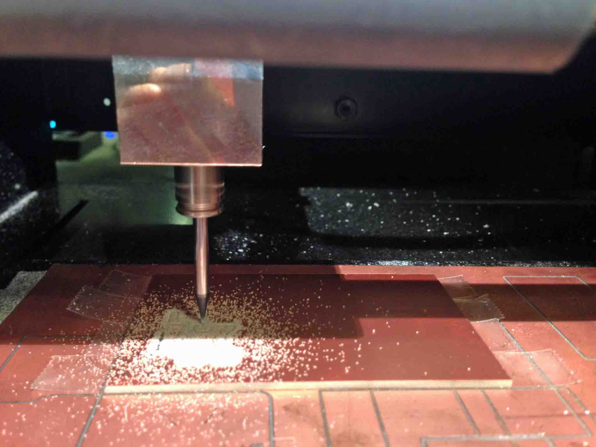
I milled my board in one go. Two notes on this process.
(1) Invert your PMG image when you open it in the fab module. Otherwise the mill will remove the trace pattern and leave the negative space. This is ease to catch when you calculate your image.
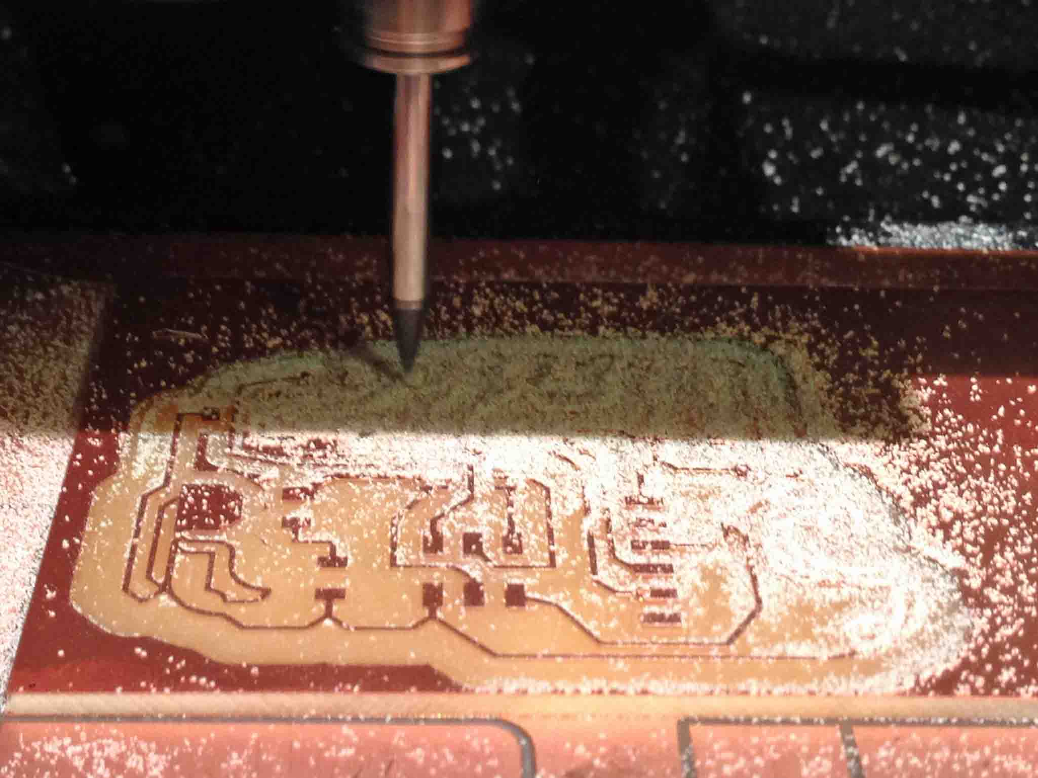
(2) The compactness of your trace design directly relates to how much time it takes to mill! This is a very good argument for AUTOROUTE, as you can optimally condense the size of your board. It took 15-20 minutes for this board to mill because there is so much empty space. It's like the suburbs on a board.
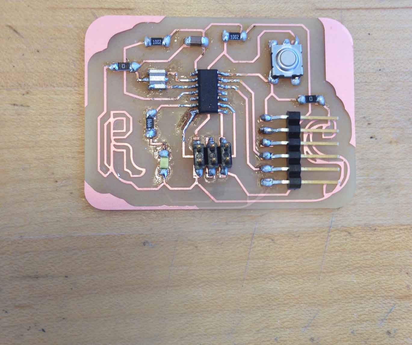
I soldered my board together cleanly - I'm really getting the hang of copper solder wick! I have yet to try to program it, so we are kept in suspense!