WEEK 8: _ measure something: design a microcontroller with a sensor and read it.
Humidity Sensor Input
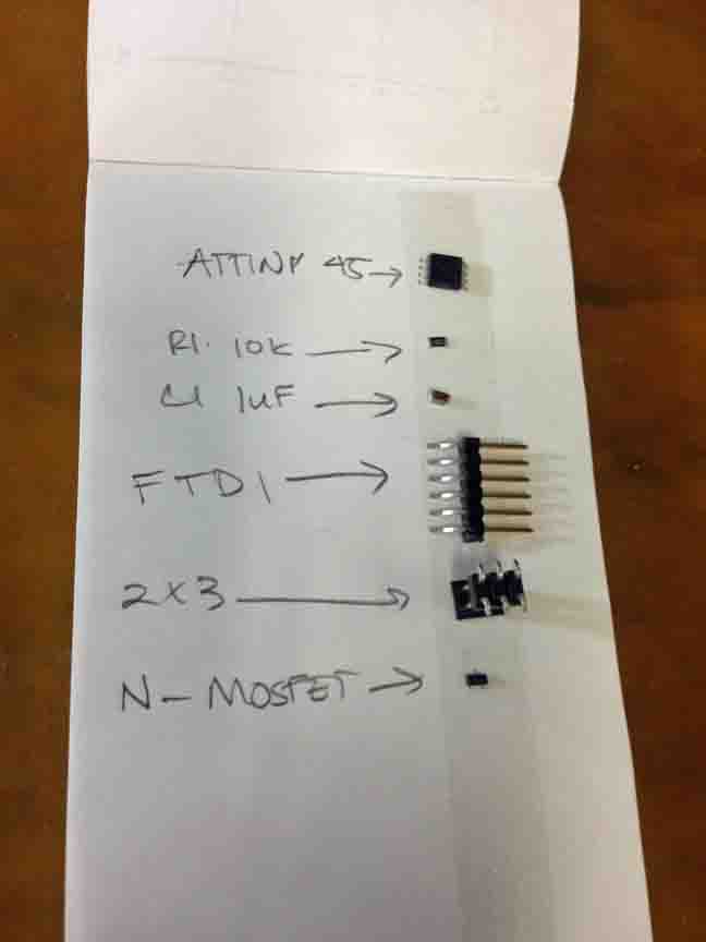
This will be my first great stab at a portion of my final project! I want to sense both humidity and temperature for the climate control of my incubator unit. I took a trip to Microcenter and came across just the thing; a DHT11 Humidity Sensor with compatibility to Arduinos (and thus, I hope ATTinys). Check out the specs on the DHT11 Humidity and Temperature Sensor Data Sheet.
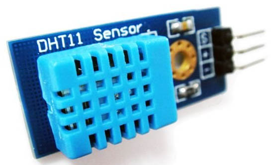
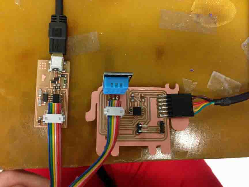
As you can see in the pic above, my sensor comes mounted on a board with a resistor and capacitor included. There are three pins, GND(-), VCC(+), and data, respectively. Also, on the data sheet there is some very cool info on the communication process which this sensor has with the microcontroller, but we'll get to the in a bit so hold tight!
Input Board Design
I'm getting rather fond of board design. One thing I forgot to mention in the original electronic design week:
(1) Set you design rules *FIRST* with the design rule doctor! that way, nothing ever gets drawn to close in the first place. I use 16 mil for wires and 12mil for just about everything else.
(2) Drag in your components and detangle with the Ratsnest function.
(3) Use Autoroute! What magic is this? Iterate with where your piece lie to help out the optimization function and you should be good to go with minimal jumpers.
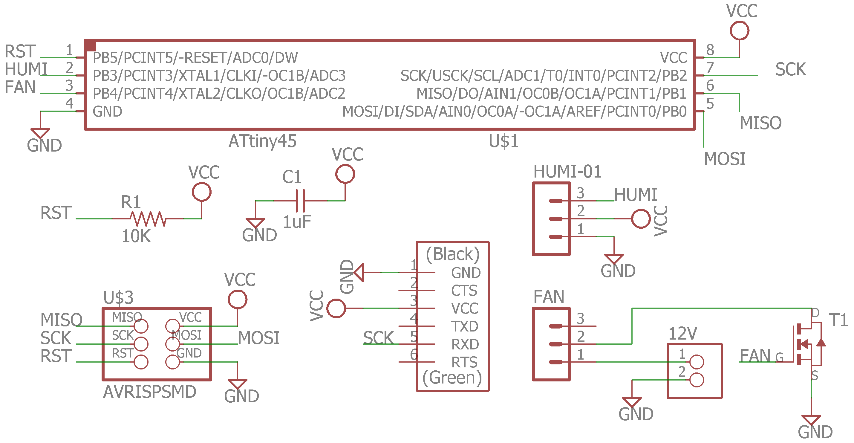
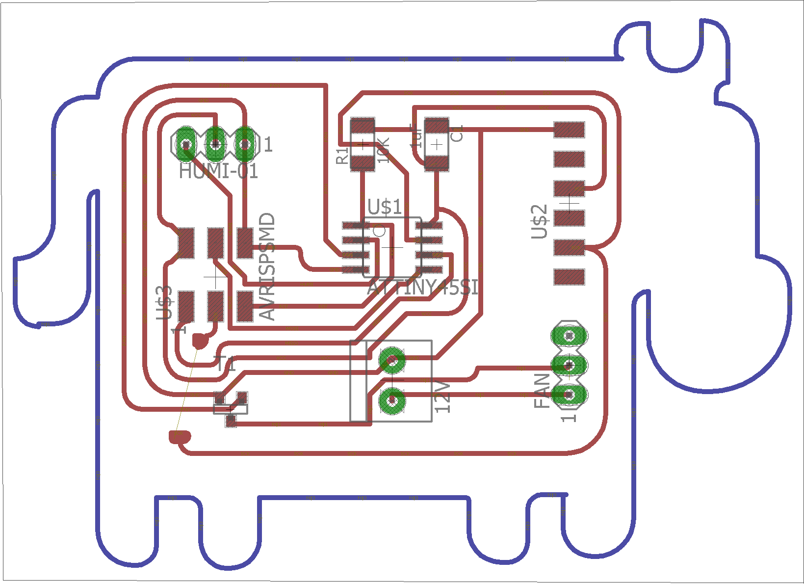
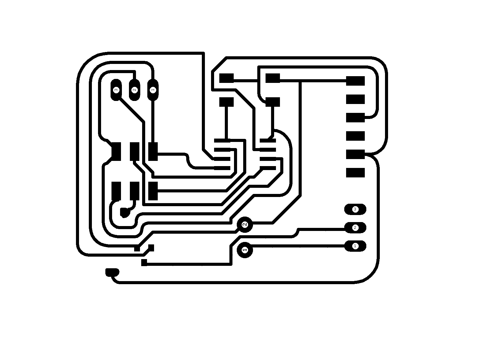
I designed the board with a few bells and whistles. This includes a fan, as a potential output to mi the air being sampled or to vent in air, i.e. decreasing humidity and creating a feedback circuit for a full humidistat control. This standard computer fan runs on 12V, and thus is going to need an external power source. So, in this circuit I included hook-up for a second power source and an N-mosfet switch which would feed it to the fan and isolate it from the rest of the board. Exciting!
The board happens to be a cow.
What can I say, i'm getting more comfortable and playful in Eagle.
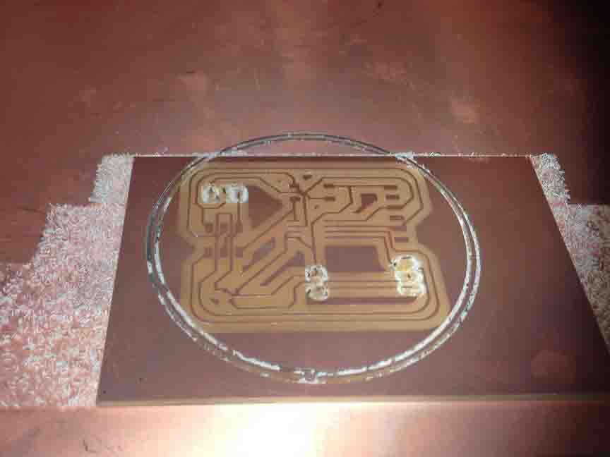
Input Board Fabrication
A quick note on milling vias! When you export a via 'pad' from Eagle, this is NOT what you want to send to the mill to make into a hole. You will get a doughnut! (See pic). The best way I have found to make the via traces is to export the PNG of the vias into a PNG. Then open it in Paint, and 'fill' the inside circle of the doughnut with a color. Delete the outer circle. (Remember to include it in your traces, so it will be there in copper).


Programming (and Troubleshooting) an Input Board
This week's coding posed a bit of a challenge because this sensor does not provide a simple output. When directed to serial print an analogue or digital read from the sensor pin, I got only "1024" or "1" respectively, which is just maxed out.
To help, Arduino provides a library specifically for reading DHT sensor commands. It is actually very approachable (Check it!)
Many modes of failure discovered and corrected included:
.
KNOW THIS!
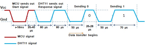
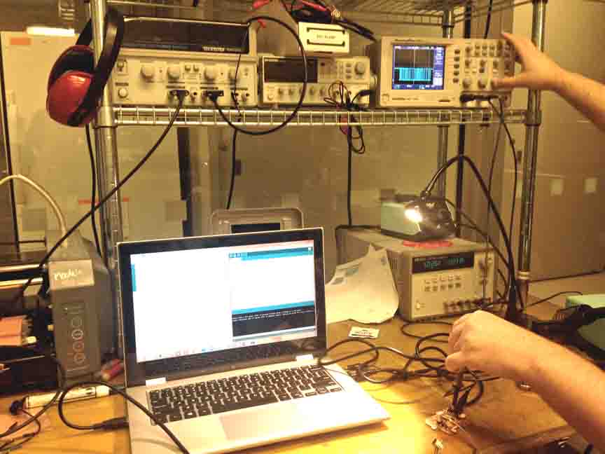
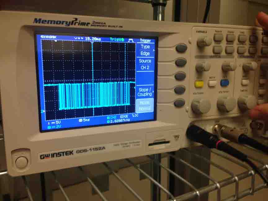
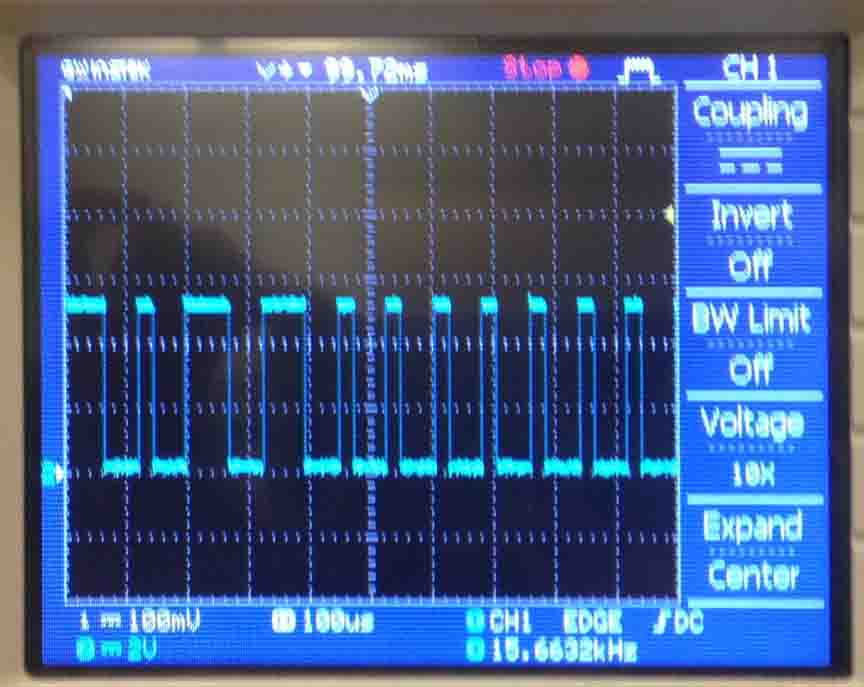
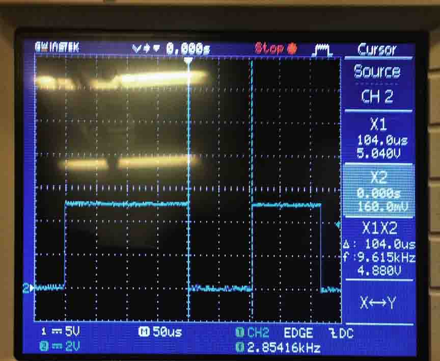
This electronics blogger actually decoded the '1's and '0's of the data package to confirm the humidity and temp information coming through the line.
"Just like the data sheet said, 80 us LOW, 80 us HIGH, followed by 40 bits of data. The HIGH bits are 70 us long, and the LOW bits are 26-28 us long. Writing this bit stream out on a piece of paper, I got: 00110111 00000000 00011010 00000000 01010001" .... a little python later, this is decoded to [55, 0, 26, 0, 81] or 55% Humidity, 26deg C, check sum. Very cool - I see something similar in my own scope view.
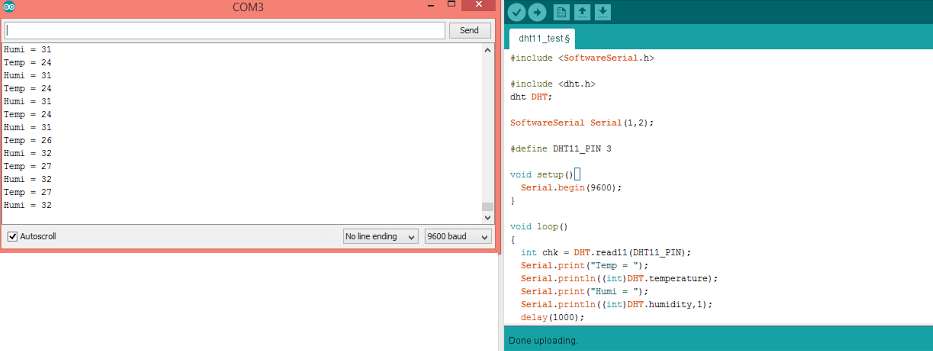
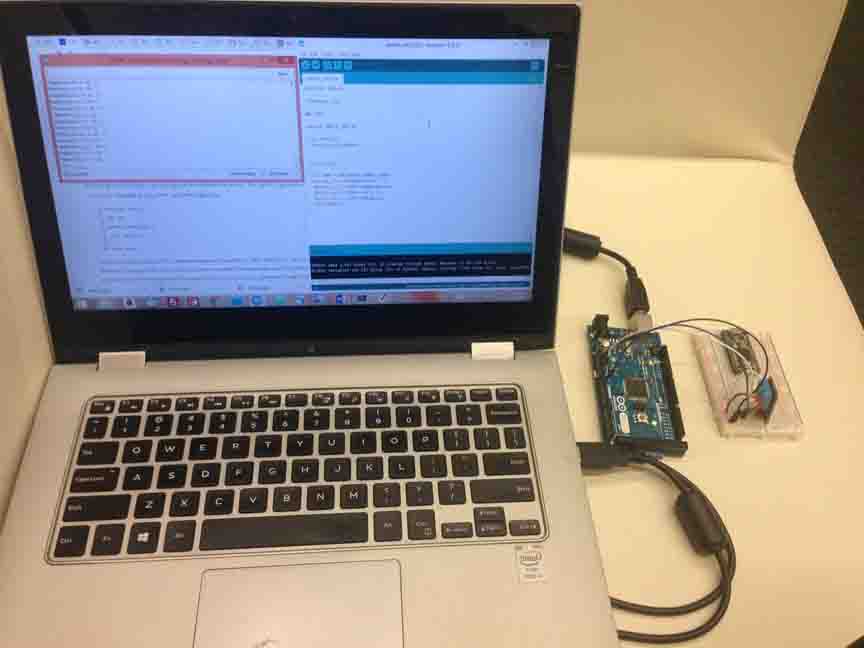
Finally working!! Here is the final code
#include
dht DHT;
SoftwareSerial Serial(1,2);
#define DHT11_PIN 3
void setup(){
Serial.begin(9600);
}
void loop(){
int chk = DHT.read11(DHT11_PIN);
Serial.print("Temp = ");
Serial.println((int)DHT.temperature);
Serial.print("Humi = ");
Serial.println((int)DHT.humidity,1);
delay(1000);
}
And the serial output: