--How to Make (Almost) Anything--
--Week 01--
--Final Project Tracking--
--Possible final project
Coming into this class, one of my core objectives was to be able to rapidly prototype components which comprise an extensible solar energy solution. For this to be feasible, the capacity of each component should be easily scaled up or down to fit the needs of the workload (for either residential or SMB usecases) That said, the following Figure 1 depicts my GIMP attemp of illustrating what the major components of said solar system would be.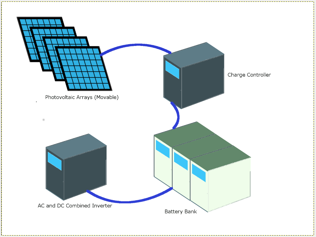
Figure 1: Final project design(Speculating)
--Pivot to bicycle helmet for turn and brake signaling
The pain point here is that some bicycle riders find it awkward to put their hands out when they want to signal turning left or right, and often times, when it is dark, these hand signals go unnoticed. So I want to create a bicycle helmet that will sense angle position change, as well as drastic changes in acceleration, and use this information to determine whether a rider wishes to turn left or right, or whether brakes are being applied. Lights will then illuminate and flash on the helmet in accordance with how car indicators work. Figure 2 below depicts what this might look like.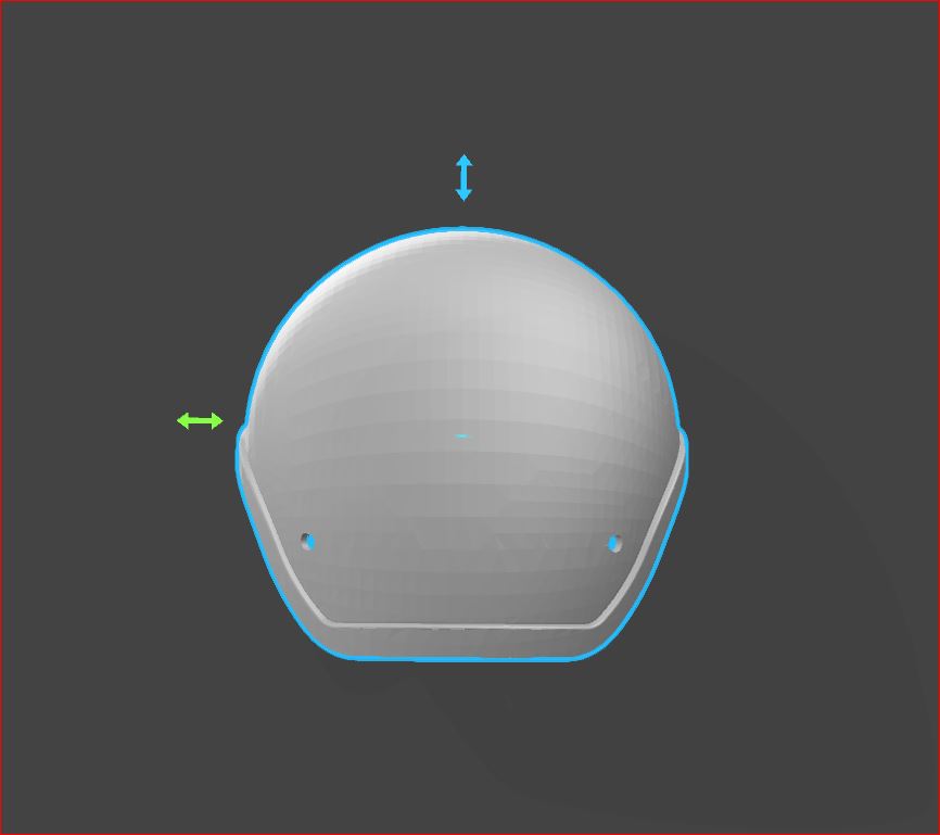
Figure 2: Final project design (Settled)
During the input devices week, I was unable to find the accelerometer I designed my board with, but since then I redesigned my board with the part that we had available in lab. I also designed a board, which I will consider my main board, with a Atmega328 IC, on a board that exposes input and output pins for easy access and connection to subsequent peripheral boards; for instance, the accelerometer sensor board would be one that will connect to it.
I milled out both boards, but there was some difficulty I experienced with the picth of the pins on both the 328 IC, and the accelerometer. After designing in Eagle, I needed to adjust the width of the pads to allow for more spacing for the tool diameter of the 1/64 bit on both the SRM-20 and the Othermill. Figure 3 is a depiction of the board designs, and Figure 4 is a depiction of the trouble areas as shown by Neil's software for the SRM-20, as well as by the Othermill.
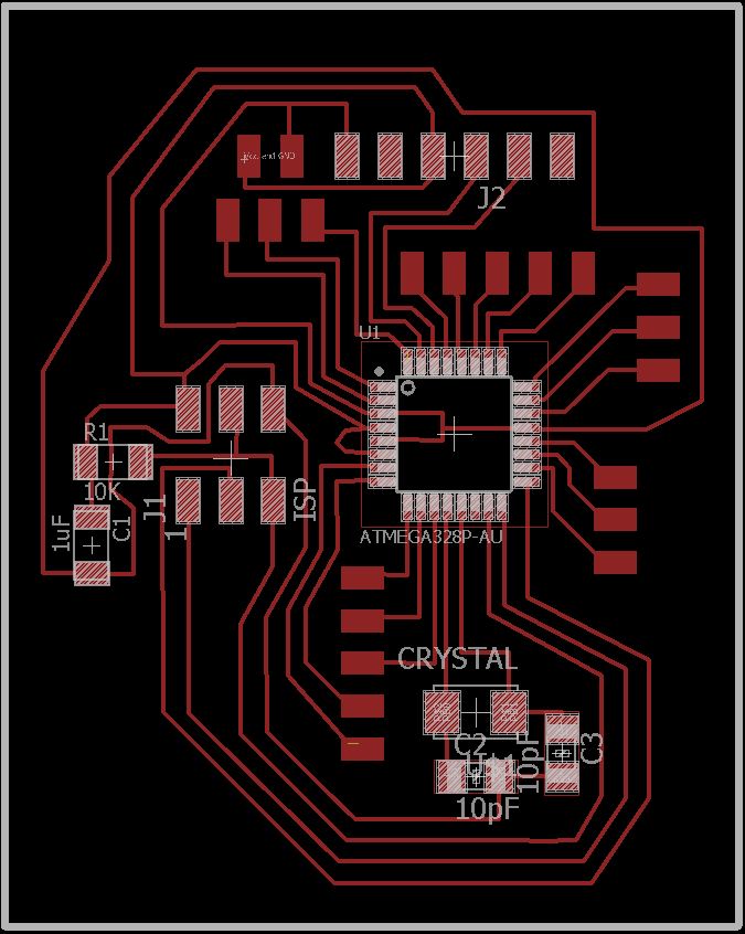
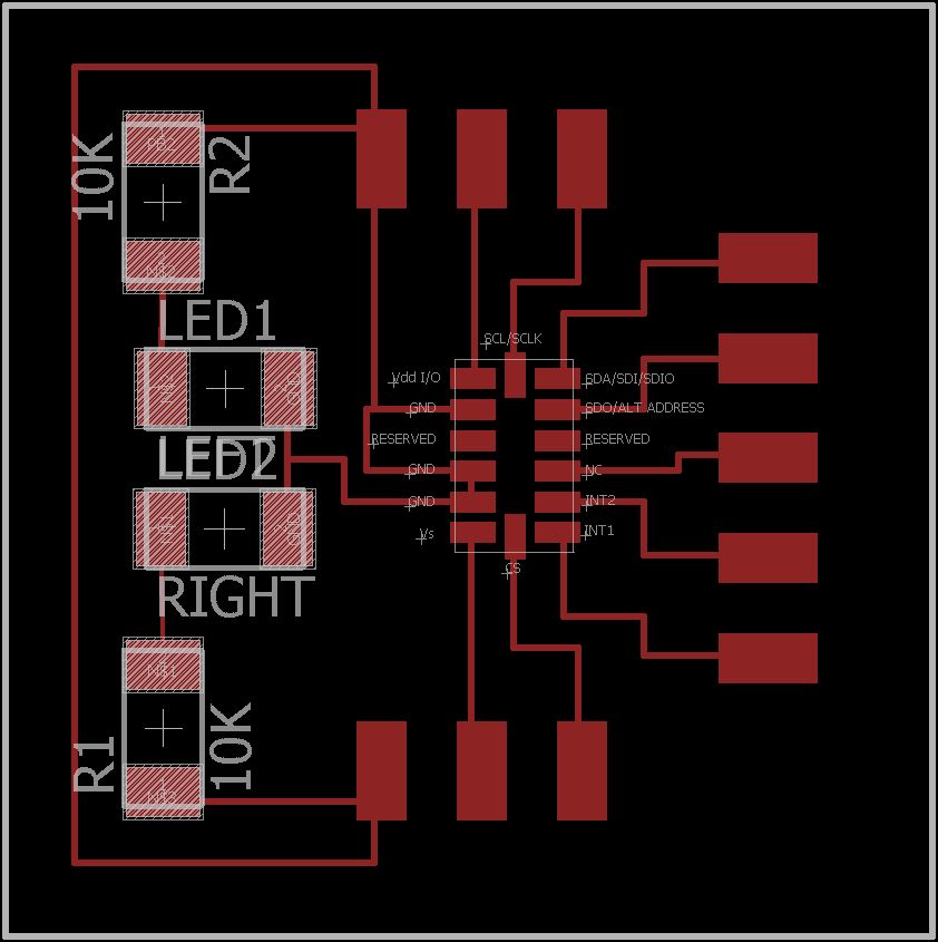
Figure 3: Atmega328 and Accelerometer board designs
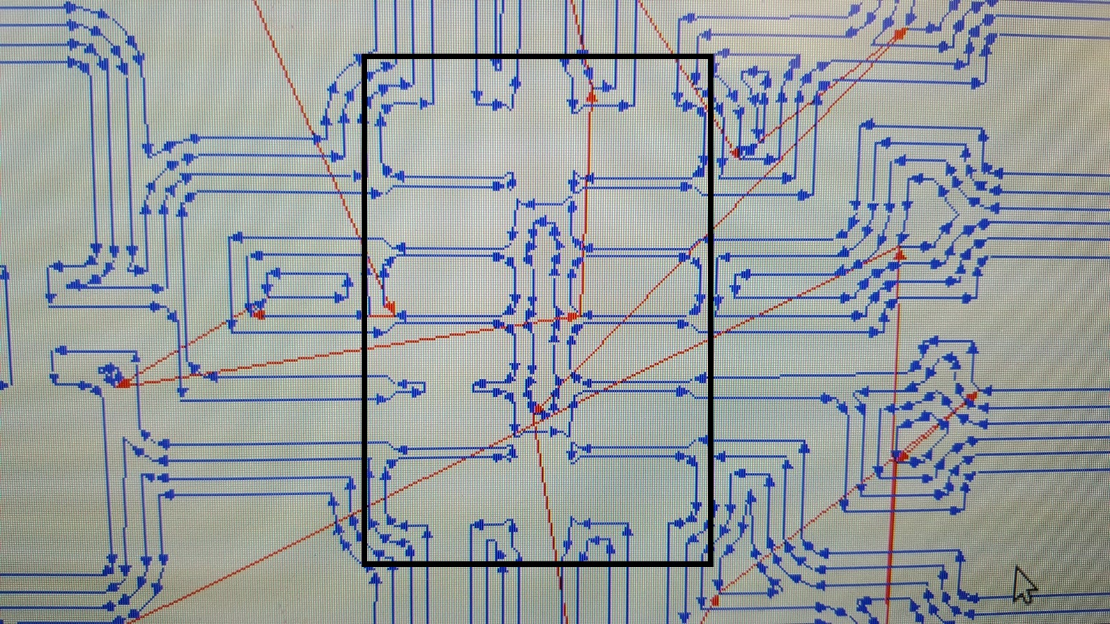
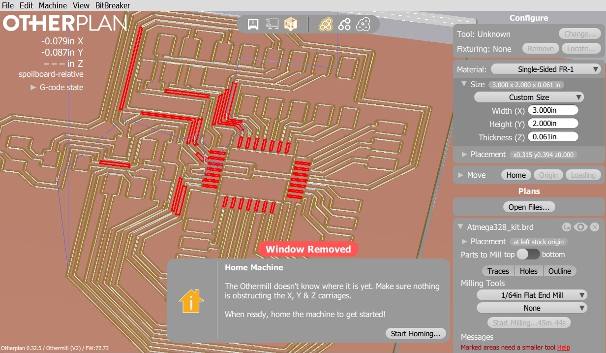
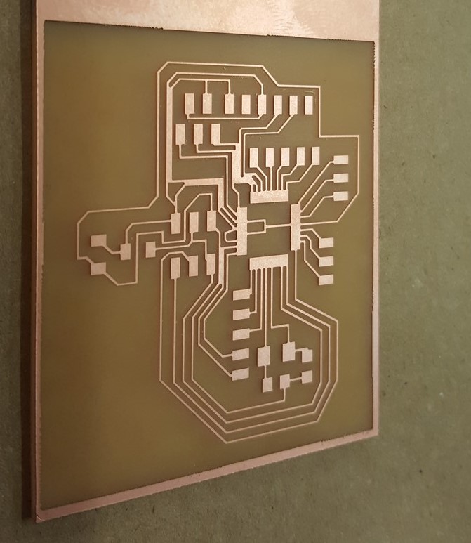
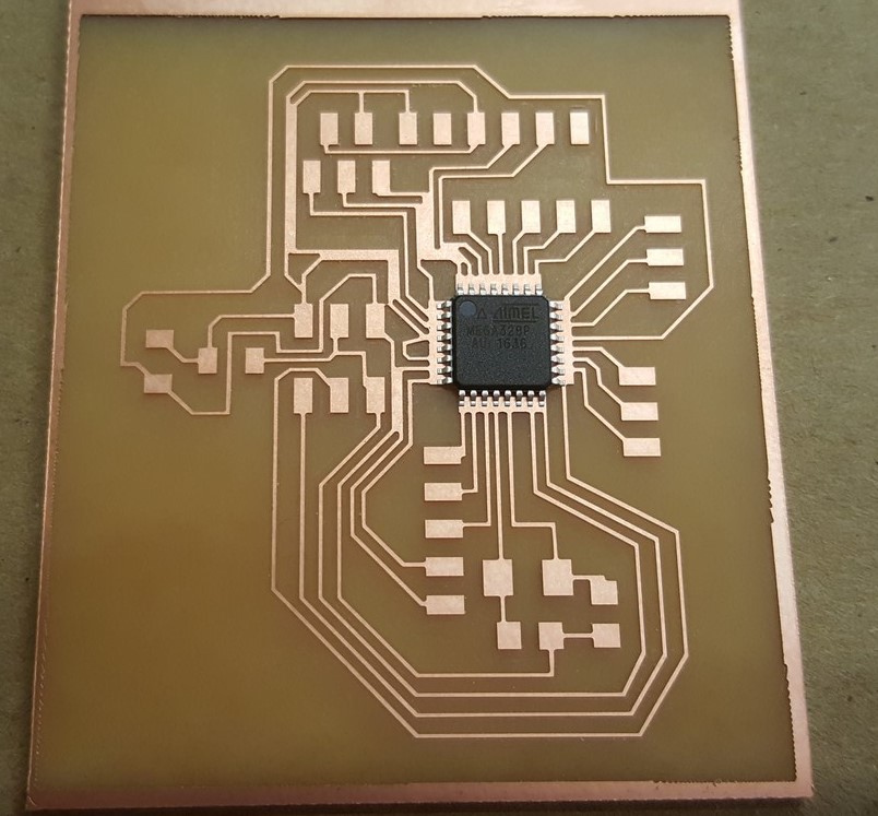
Figure 4: Trouble areas on board (SRM-20 and Othermill software)
I edited the pads of the boards using Microsoft Paint - just to see if it would make a difference, and it did. The next step was to mill out the boards and then solder the components on, for which I started with the components on the board that would prove most difficult to solder. On the accelerometer board that would be the accelerometer, and on the 328 board, it would be the 328. I had to do a reflow method for the accelerometer board. The process was to place solder on the pads on the board, and wick out the excess so solder was only on the pads. I then did the same for the pins on the acceleromter itself (this was unexpectedly easier than the board - solder separated easily and only stayed on the copper pins). I placed the accelerometer on the board and used a heat gun targed to that area, to melt the solder on both the board and the pins to fuse together. Figure 5 shows what I discussed here.
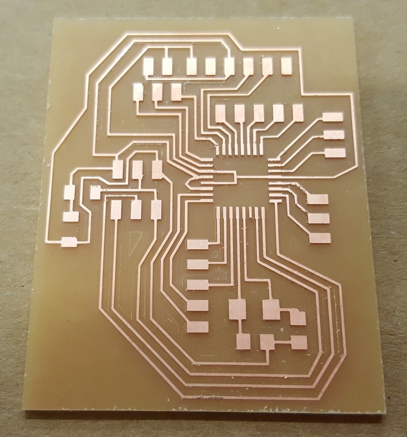
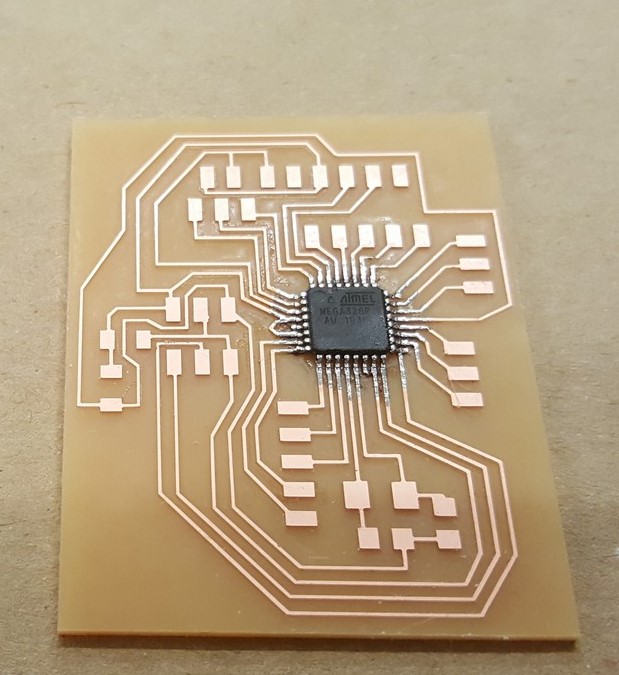
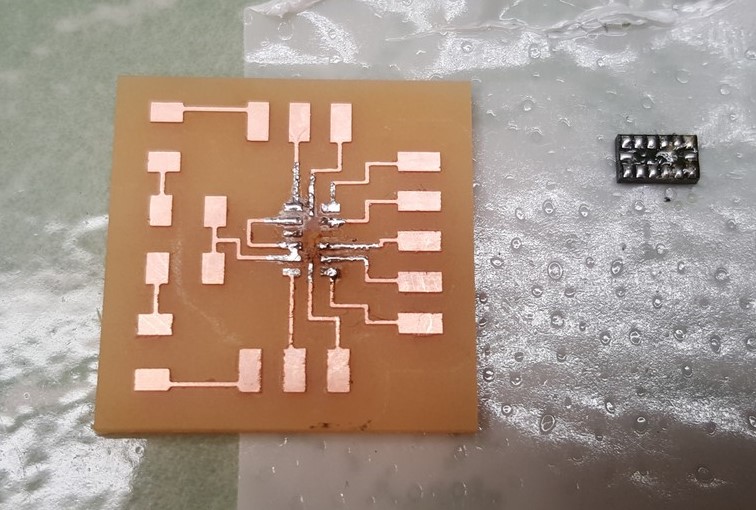
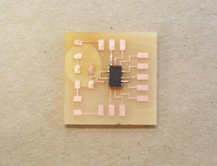
Figure 5: Stuffed 328 and accelerometer
--In the interest of spiral development...
In the interest of spiral development, I wanted to focus on the functionality of the indicators - first with the LED turn signal indicators in the front and in the back, then the headlights and rear reflector lights, then finally, on the braking system (all initially done in a simple enclosure (in this case a box), and then taken and applied to something that can be put on any helmet, i.e. a band that wraps around any bike helmet, and then finally a full bike helmet. Let's see how far we get.... For the purposes of this class, if I can successfully get a working box with indicators, headlights, and rear reflectors working, with some tilt sensing mechanism communicated via I2C, then I will consider that a success.
... towards a successful final project implementation!
All files for the rest of this process can be found here.
--Step1: Design and mill the remaining PCB boards
In the spirit of spiral development, I needed to design the remaining boards for the functionality I wanted - an LEDs board, an updated Atmega328 kit,
a switch board (connected to a battery back and a voltage regulator), and then board with those two initial designs together (ultimately
did not work out from a testing stand point, but the design was solid - I will need to update the design). The following figures 6 to 11 depict the
process.
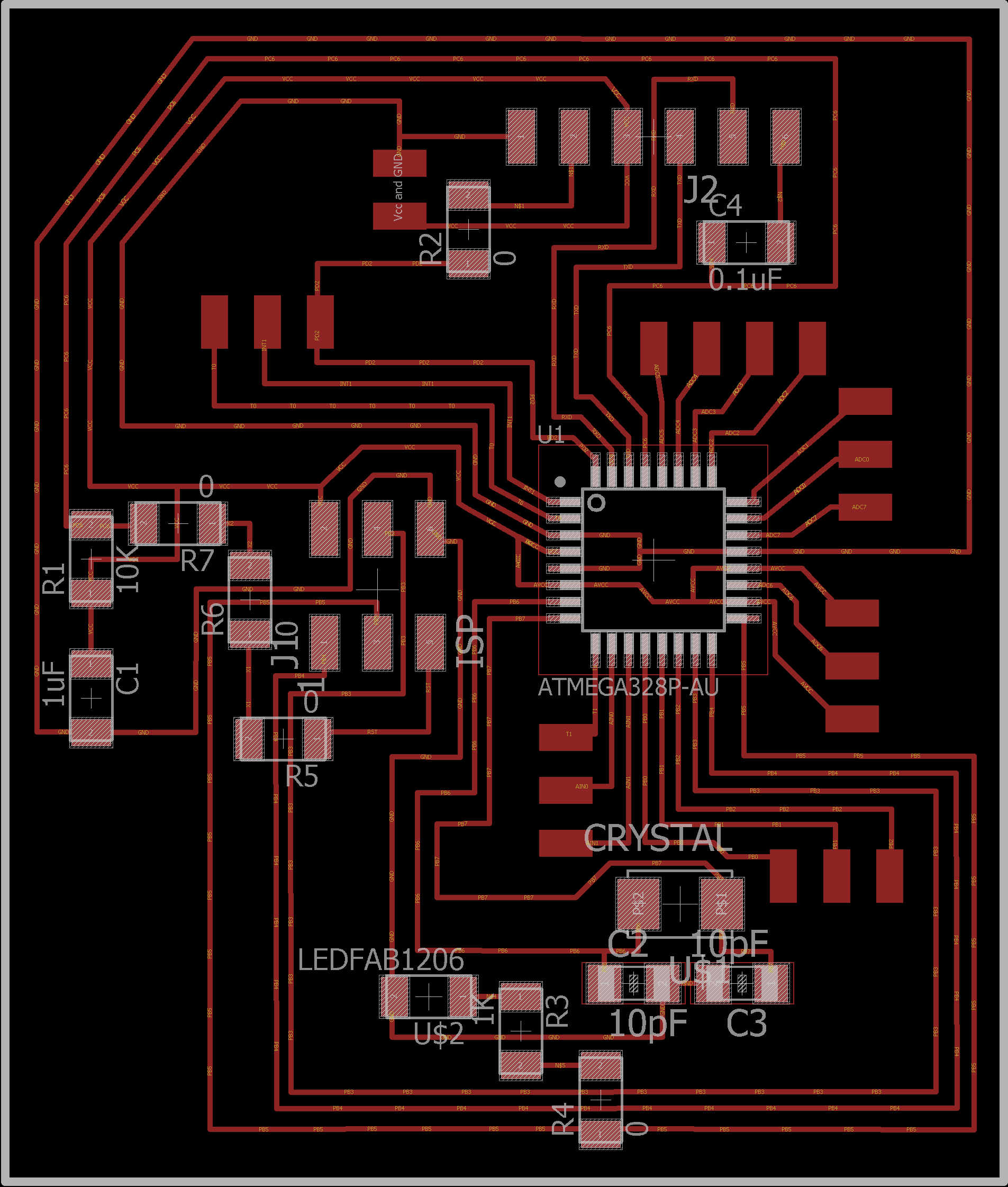
Figure 6: Updated Atmega328 kit design
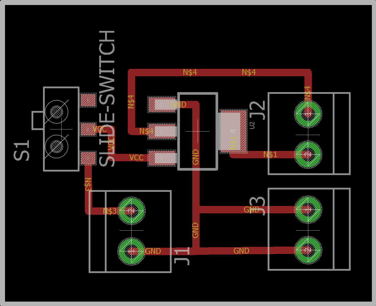
Figure 7: Atmega328 and Accelerometer board designs
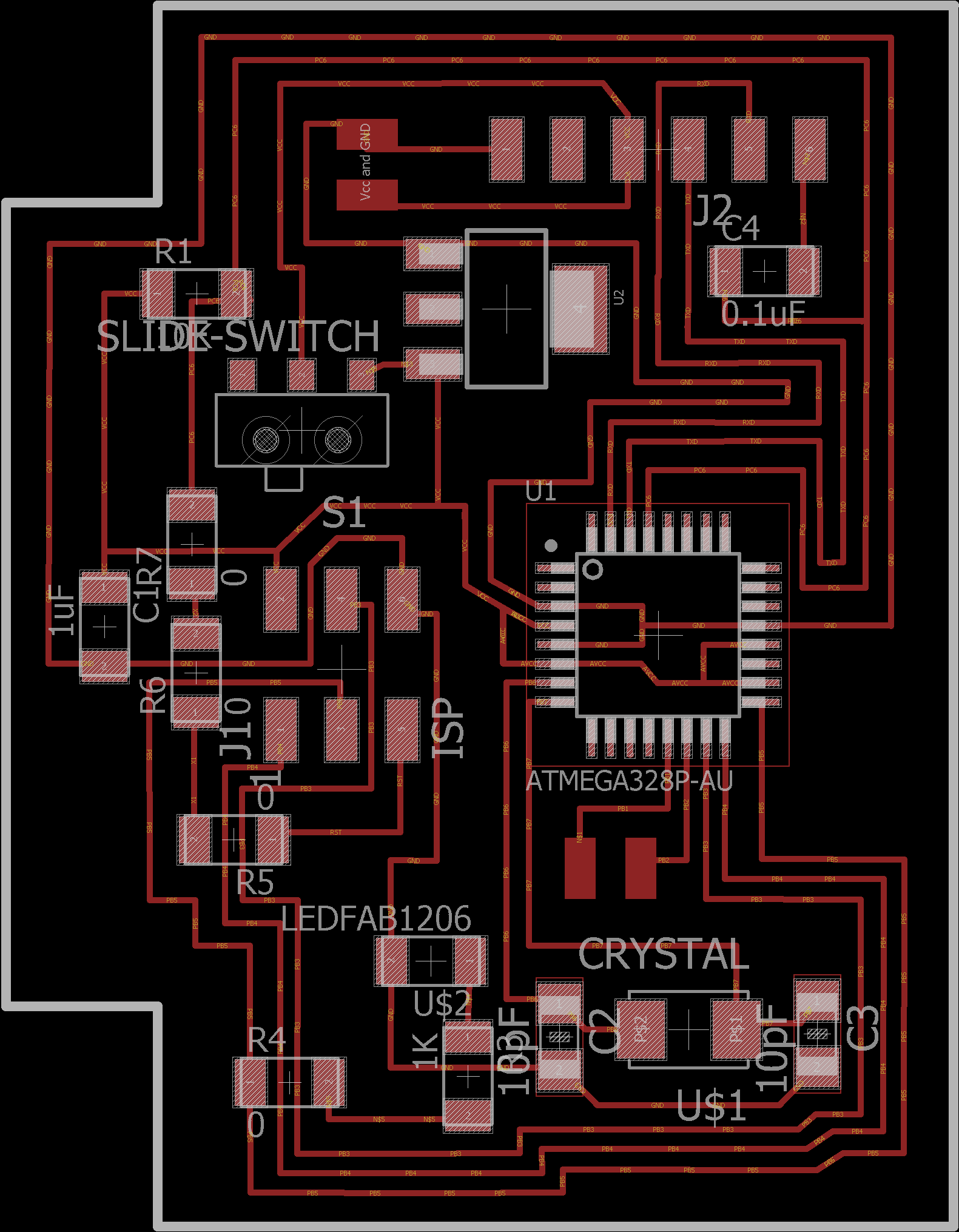
Figure 8: Combination of switch board and Atmega328 board
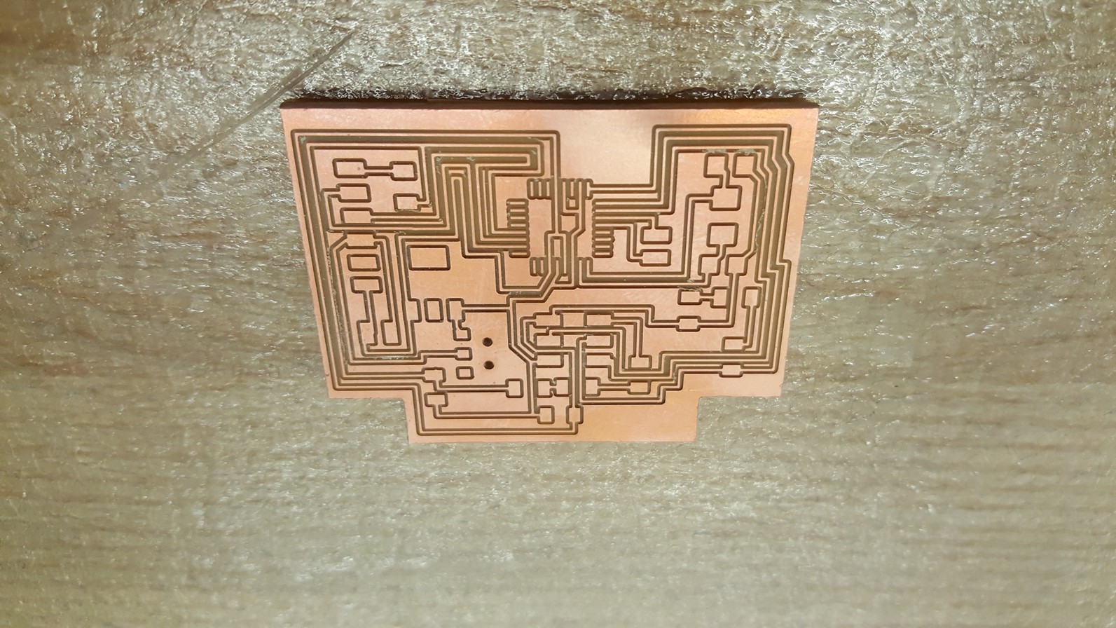
Figure 9: Milled out combination board
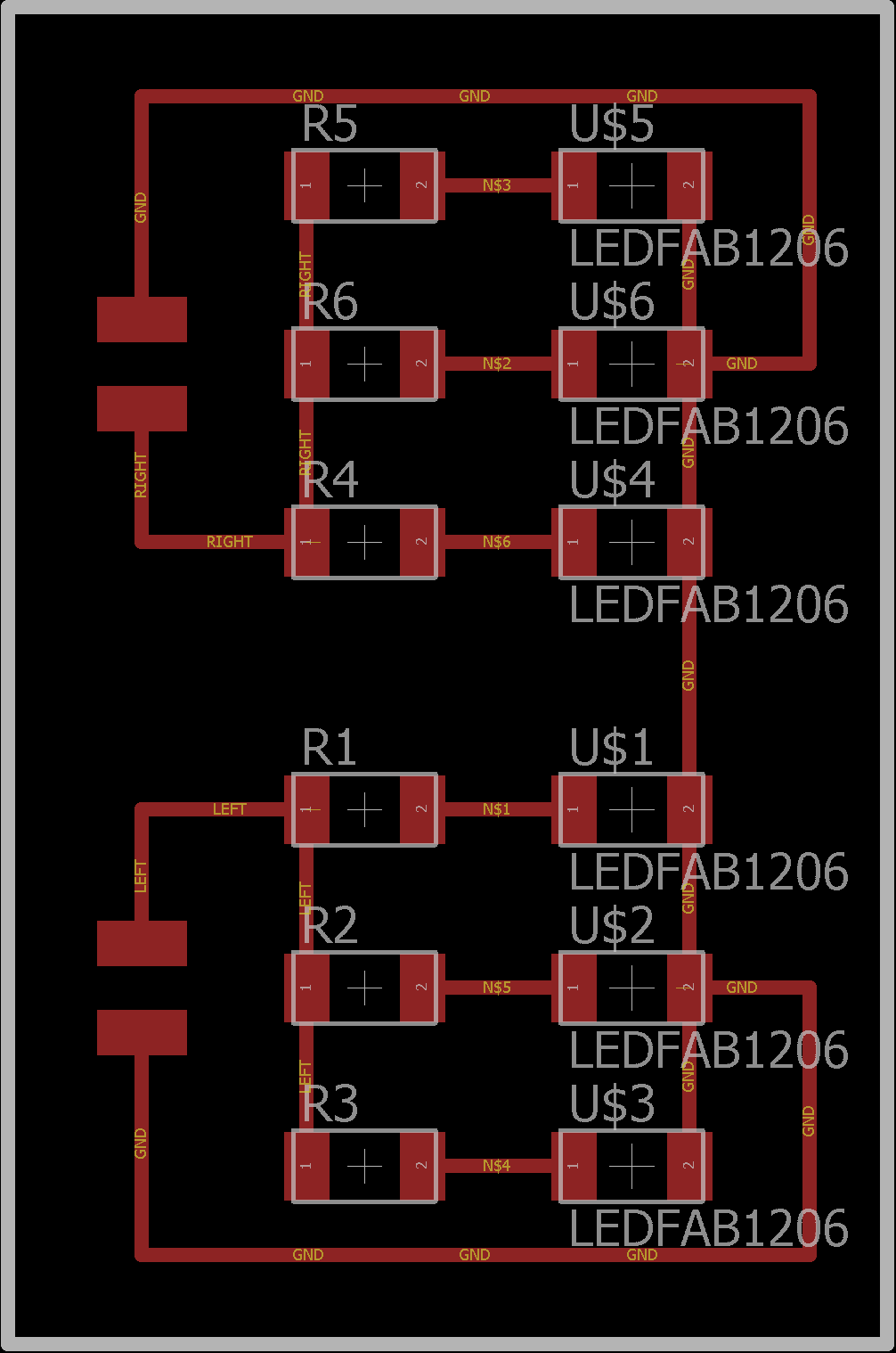
Figure 10: LED board combined on one PCB for testing
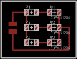
Figure 11: Individual LED board design
--Step2: Get the communication protocol working
Here I needed to get the communications protocol working (something I have been battling with for a long time) I was able to finally troubleshoot and determine that I had the wrong pins for communicating, and my board with my accelerometer did not have the right connection. I looked at the class site and cross referenced the connections from the t45 to the 328 and the ADX343 PAINSTAKINGLY! This ultimately worked, after I redesigned the accelerometer board.Spiral development: Test LED board with the microcontroller board for one pin, then two pins, then test the tilt sensing mechanism in code (here I needed to extrapolate from Neil's ADX343 python file for the "two's complement code", and this ultimately worked).
Working LED Board
Working LED Board on both sides
--Step3: Program the board to display tilt sensing mechanism
Working accelerometer sensor test (FINALLY!!!!)
I2C finally worked on this board, and like I mentioned above, the problem was with my connections
on the accelerometer board. As soon as this was corrected, I modified the code on the repo (Neil's hello world
code for the accelerometer), to get the functionality I needed, after testing that the base code worked (with
some minor tweaks to pins and input output conditions from the t45 that was used in his board design, to map
to my Atmega328 for my 328 kit used for this project.
Now I tested the sensor flash routine for left and right turn signal indicators.
Pulling the input from the accelerometer via I2C, and then converting that 2's complement
data to an integer value to check against - this value is used to determine angle of tilt.
Final working functionality, as the video below shows: Now I can make the enclosure.
Pick up the device and keep it horizontal, and the LEDs go on as headlights and rear indicators,
then turn one direction or another (over a particular threshold), and the LEDs respond to whichever
direction. Place the device back down, and it turns off. All done in C programming.
--Step4: Design the enclosure and put the parts together
The following figures depict the steps I took to put the parts together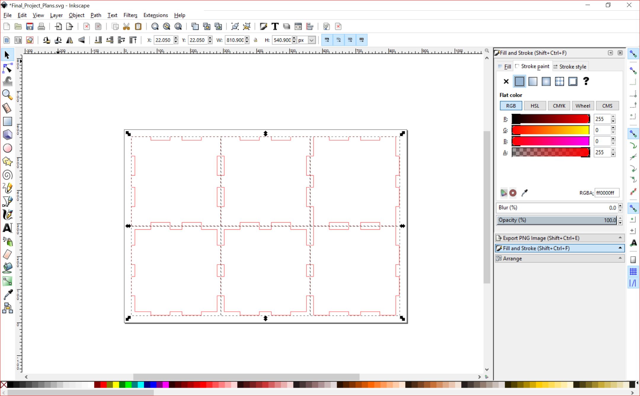
Figure 12: Box Design
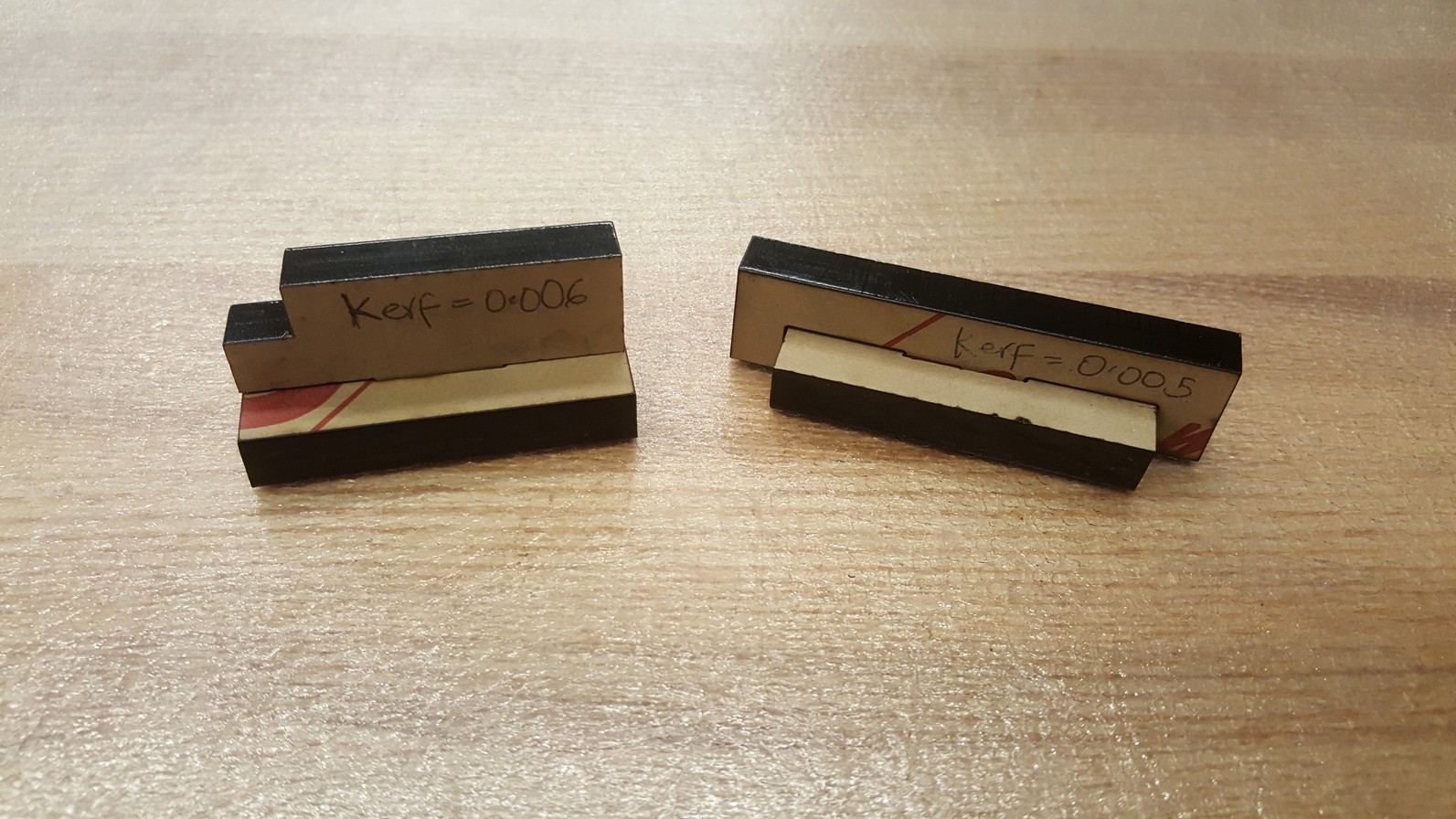
Figure 13: kerf Testing
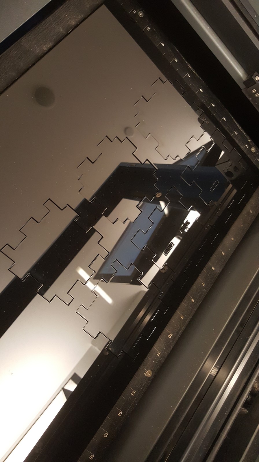
Figure 14: Laser cutting the box
Laser cutting the box
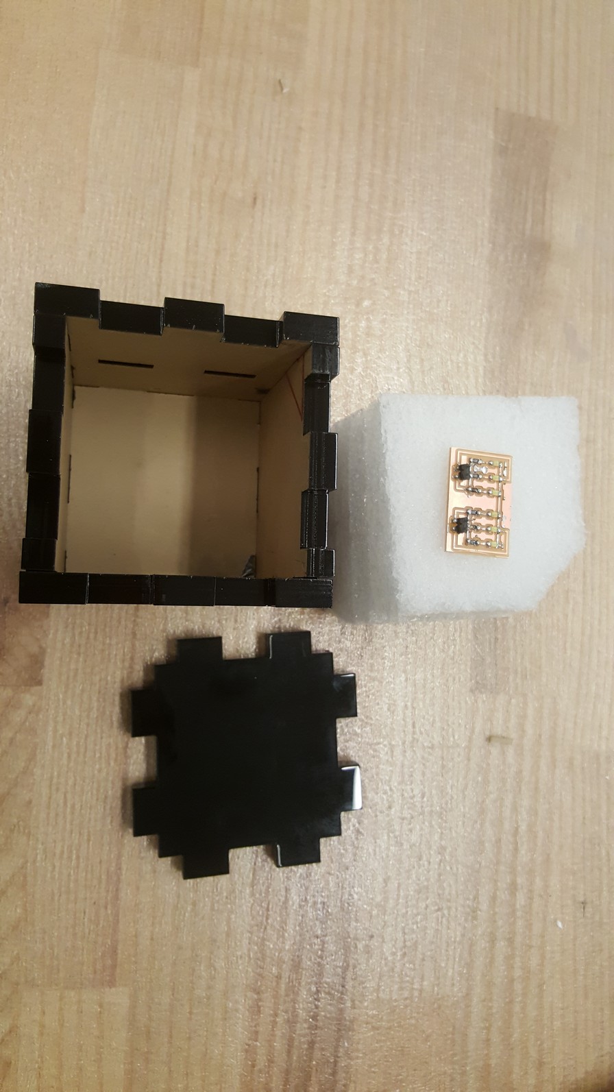
Figure 15: Foam inset and the laser cut box
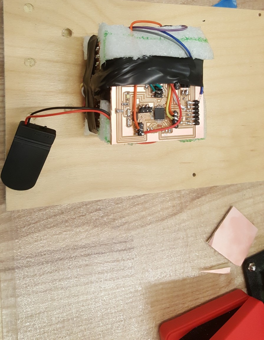
Figure 16: Stuffed foam inset with the battery enclosure, and the laser cut box
Figure 17: System in the enclosure
--Step5: Test the final product
Final working product test
The next step I'm leaning towards would be to follow this up with a design of a band that one
can put on top of a helmet, or just on the head, to provide the functionality, for cyclists and
runners (night runners, specifically) alike.
Long nights, but it was worth all of it!