--How to Make (Almost) Anything--
--Week 02--
--Computer controlled cutting--
--Step 1: Designing the layout in software
The idea is to design building blocks that are composable and stackable, to form diferent structures. This can be used, for instance, for modeling a modular enclosure for housing solar system components, or can be used for modeling composable furniture. This step involved picking a software package (Inkscape) which served as a design interface to develop a parametric tile design for the sides that make up individual cubes. These cubes stack up as building blocks for a variety of structures.The smallest units are the tiles, of which I determined that there will be three main types needed for a complete cube, based on the interlacing design illustrated in Figure 1 below. Tile types 1 and 2 form the vertical walls for the cube, where similar tile types are placed opposite to one another. Tile type 3 serves as the top or bottom which completes cube building block.
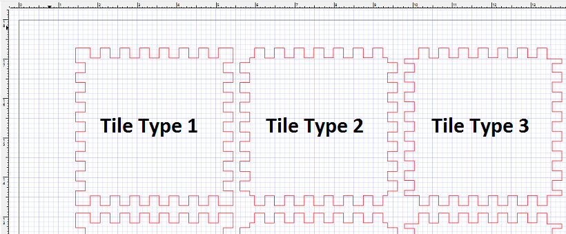
Figure 1: Different tile types designed in Inkscape
--Step 2: Cutting with the laser cutter
CorelDraw is the interface of choice for the laser cutters in the EECS lab, so before the cutting process actually started, my tile designs needed to be ported to in an SVG format to the workstations connected to the cutter, because for this specific design, PNG offered poor resolution for adequate cutting. Once the design was loaded into the workstation, I proceeded with the checklist process to ensure that the laser cutting machine was ready to begin the the workload.First ensured that it was indeed turned on, then ensured that the compressor was turned on, and that the machine was properly focused. At this point, I verified in CorelDraw that the thickness of the cut was set to hairline width, and that the color of the lines intended to be cut was set to RGB Red. I then used cut power and speed settings from our group assignment (60% power and 10% speed, and a thickness of .140in) as an initial point for a test cut. Once I verified from the testcut that the settings were adequate, I proceeded cutting an entire 30in x 18in sheet of cardboard with a composition of tiles to cover the entire surface - This is depicted in Figure 2 below
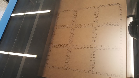
Figure 2: Laser cutting the tiles
--Step 3: Assembly of a single block
The tiles are cut at this point. So the next step was to see how they fit. I should mention that during the design stage I ensured that for the coupling mechanism to fit and hold properly, that the male sections wer slightly larger than their counterparts - and this was fine because of the type of material being used (cardboard) - it will be interesting to see if a similar situation arises for other materials like vinly, plastic, etcetera. Figure 3 depicts a building block (cube).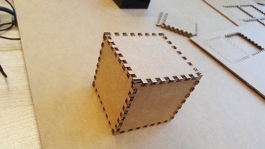
Figure 3: An assembled cube put together from the tiles
--Step 4: Stacking blocks together
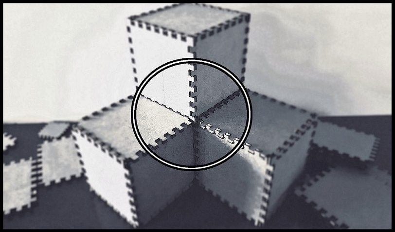
I found that for this stacking process to work properly, the walls of the boxes needed to be stacked as high, or as wide as was needed, and then the the final pieces (top, for a vertical stack, or side, for a horizontal stack), would then be placed. This was not the intended solution to my building block problem, because in this construct, the composite system is hollow on the inside. That said, It does hold together properly, as Figure 4, illustrates. However, I anticipate that what I will probably have to do is:- Make the depth of the grooves a little deeper to allow for both a horizontal and a vertical
stack (this way individual cubes will have all sides in place, yet leave room for other cubes to attach),
or
- Find an entirely different construct for the cubes to attach to one another.
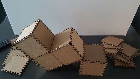
Figure 4: More complex structure from building blocks