--How to Make (Almost) Anything--
--Week 04--
--3D scanning and printing--
--Step 1: Testing the 3D printer tolerances - group effort
A key step to 3D printing is to identify how the machine you would be printing on will handle the geometry specified in the solid to be printed. The fab lab already has a "3D printer obstacle course drawing, which is poised to test overhangs, proximity tolerances, vertices, support material, hole diameters, etc. Figure 1 depicts the composite of the obstacle course in two different orientations - we did this in order to see the effect on the different solids, as a result of the different layering of print substrate.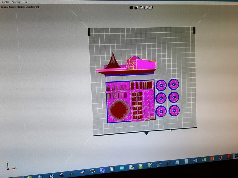
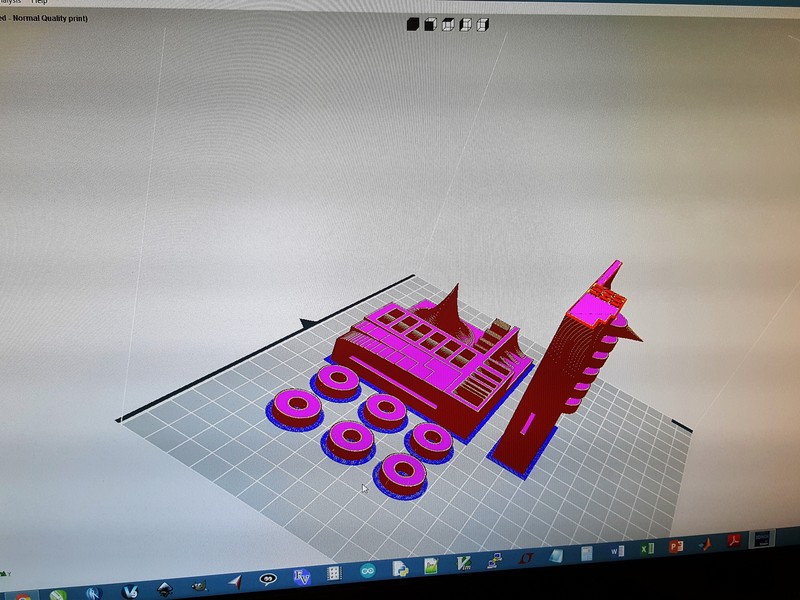
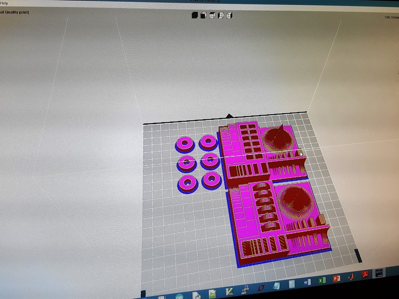
Figure 1: Obstacle course composite for the 3DWox printer
Once the images were loaded to the printer software as an STL file, and the print properties were set, the estimated time was approximately 11 hours (this was also shown on the printer LCD, once the file was sent to the printer, as depicted in Figure 2 below) - This is something to make a note of - the process, on desktop type 3D printers, is extremely slow! Figure 3 shows the final product after the print (with the support structures, and without them).
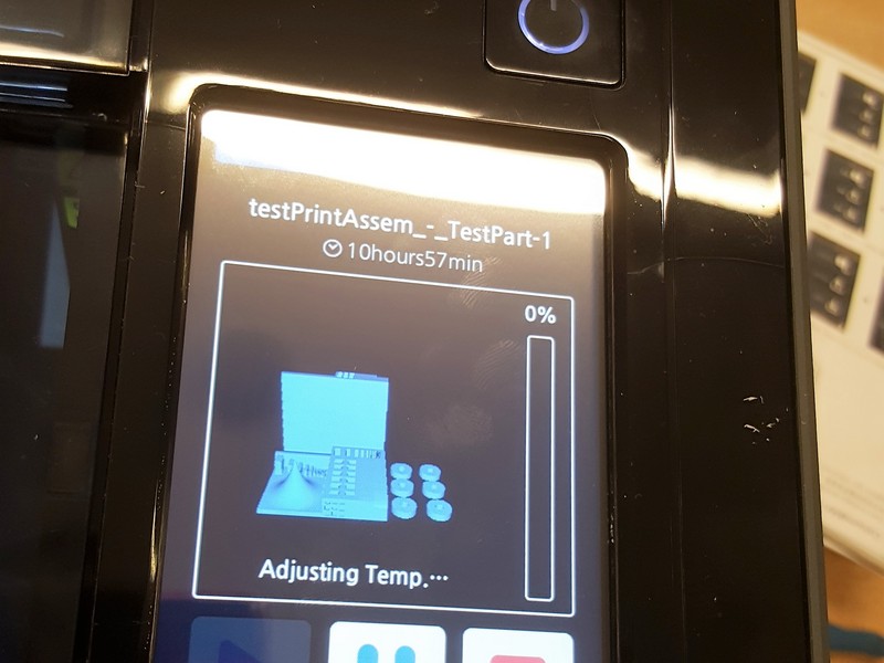
Figure 2: Time to print, indicated on the 3DWox printer
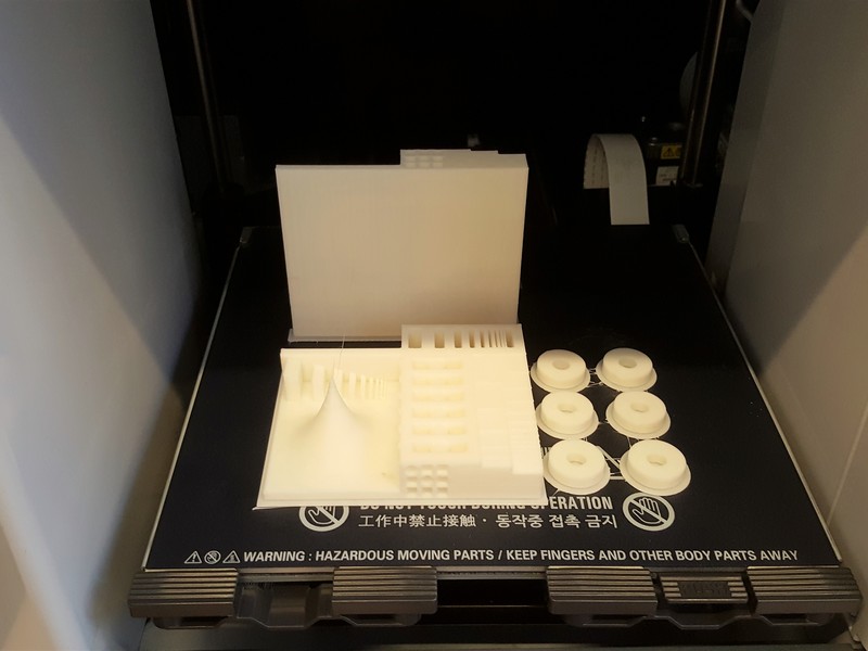
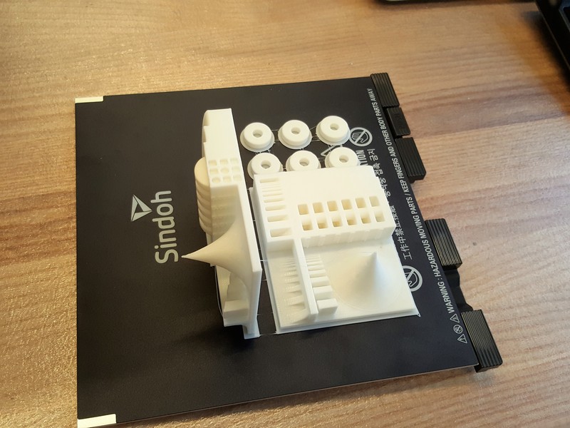
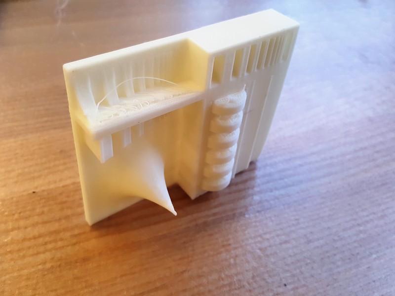
Figure 3: Finished obstacle course
In the last image in the Figure 3 set above, there is evidence of stringy deposits on the print, and these instances indicate where the 3DWox cannot maintain accuracy. The dimensions are listed on the part, so it helps to figure out where the machine starts to fail.
--Step 2: Designing and 3D printing a solid that cannot be subtractively realized
For the 3D print assignment this week, the task was to additively create something that would otherwise be impossible to create by subtractive methods (for instance, milling). I needed to brush up on my 3D design skills, so I took this as an opportunity to do just that. The solidworks program has a tutorial built in, which goes through the steps to design a pressure plate, so I went through the steps to design this pressure plate. This did not satisfy the requirements for the assignment, so I took it further and mirrored the part about the y-axis, and fused the two halves together to form what serves multiple purposes (a cable roll, a cat toy, a paper weight, and a pen/pencil holder),as depicted in Figure 4 below.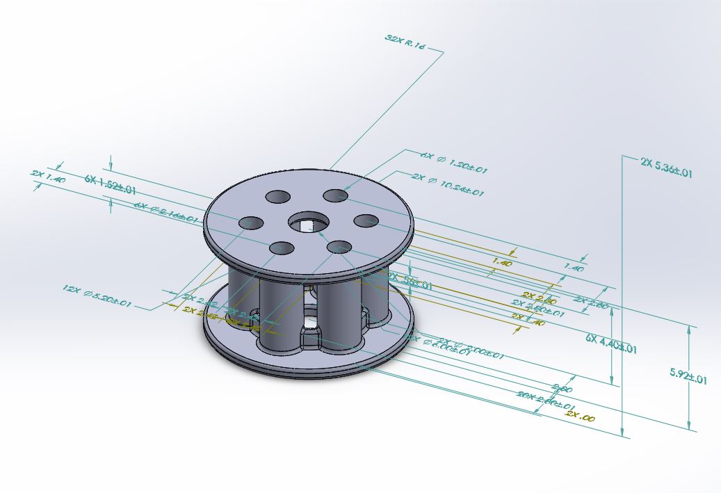
Figure 4: Solidworks cable roll design
I decided to use the other 3D printer in the EECS lab, the uPrint machine that offers better print quality. But this printer requires post processing the part, by dipping part in a warm bath after printing - in order to remove the support structures). My design was batch printed with another student's design, to make the print process more efficient for the number of students assigned to the lab. The print also took a similar amount of time as the test print on the 3DWox printer. Figure 5 depicts the layout for the printer, and the start of the print for the two solids - the blue part is the cable roll, Figure 6 shows the part after it was printed by the uPrint machine, and Figure 7 shows the part after post processing - the quality of which was much better than that of the 3DWox desktop machine (as expected).
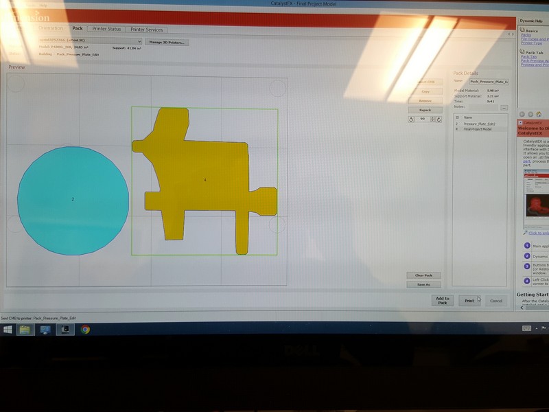
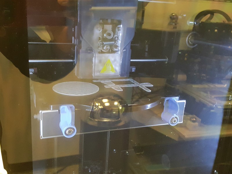
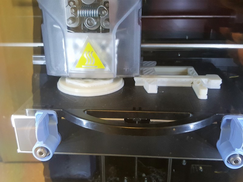
Figure 5: uPrint Printer Layout
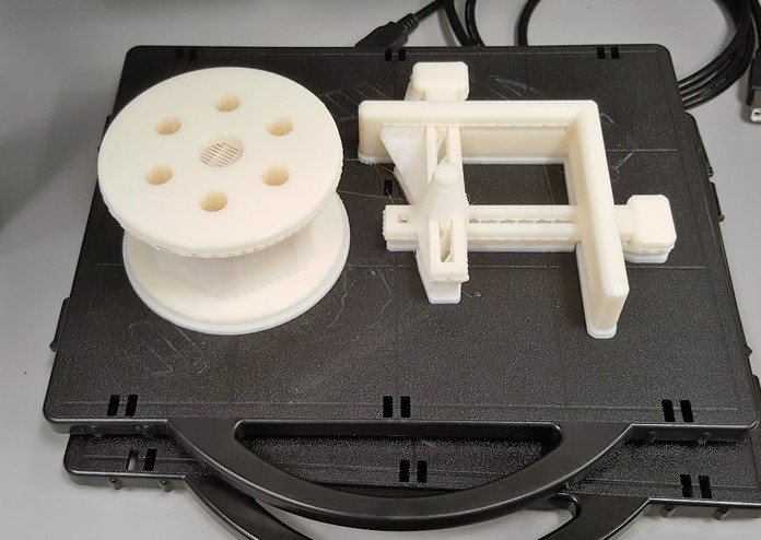
Figure 6: 3D printed wire roll, before post print processing
- from uPrint 3D printer
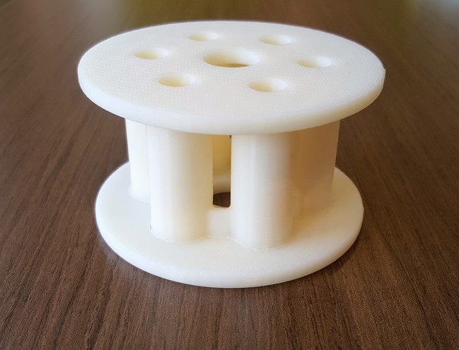
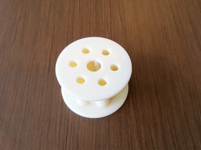
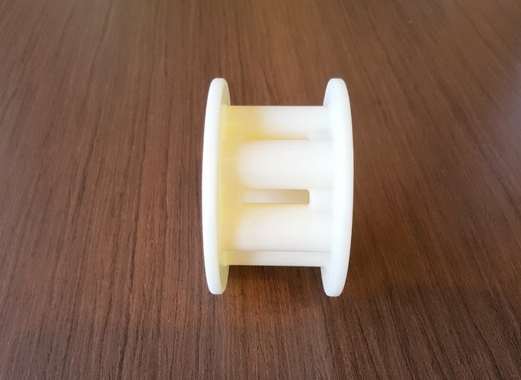
Figure 7: 3D printed wire roll, post processed
--Step 3: 3D Scanning objects
First thing I would mention is that without the right settings, i.e. lighting, background, distance, stable rotation, ..., the 3D scanning process - particularly with the "Sense" scanner device from 3DSystems. Figure 8 shows the setup we came up with in the EECS lab.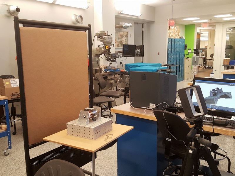
Figure 8: The EECS lab setup for 3D scanner
In my opinion, I would rather chew rocks (yes, chew rocks) than use this thing for something tangible. This thins is such a pain to use. Also, whatever you scan, ends up looking like something that has suffered extensive corrosion from being at the bottom of the atlantic for an inordinate amount of time. That said, I tested a number of object shapes and sizes to see how the scanner performed under different conditions, as depicted in the following Figures 9 thru 14.
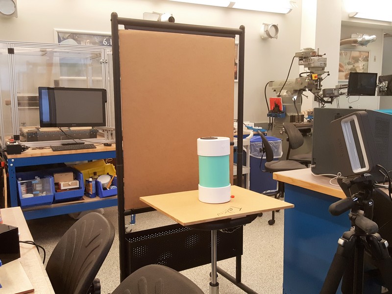
Figure 9: Vertical cylinder - loses tracking because the shape
barely changes as the platform rotates
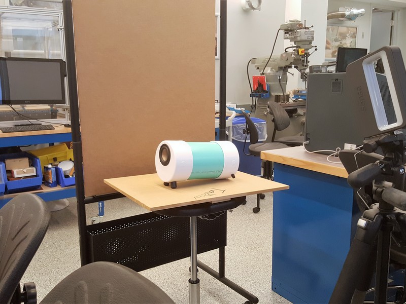
Figure 10: Horizontal cylinder - keeps tracking because the shape
changes constantly as the platform rotates
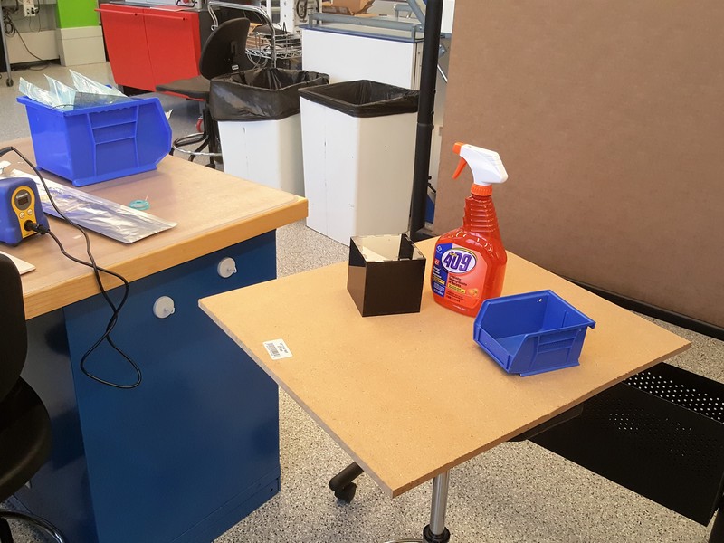
Figure 11: Multiple Objects placed on the platform to test
object recognition
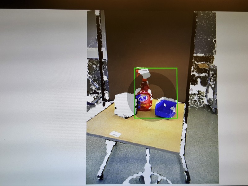
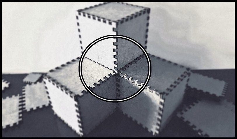
Figure 12: Black shiny cube being ignored by the scanner
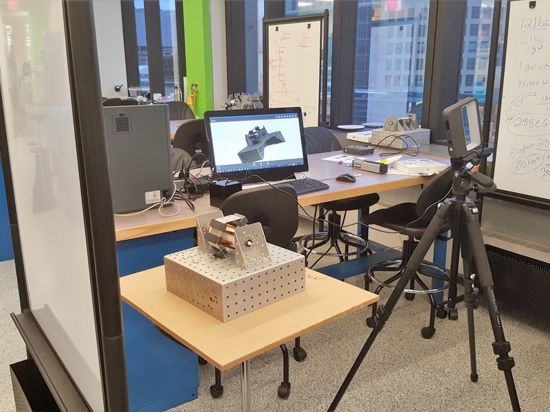
Figure 13: Inductive motor on a perforated rectangular base,
on the platform
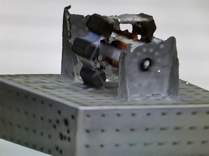
Figure 14: Scan result - poor resolution and edge detection
My determination is that the 3D scanner does not offer much value, from what I have been able to test thus far, and 3D printing is valuable if one has patience to wait for time it takes to print prototypes.