--How to Make (Almost) Anything--
--Week 06--
--Computer Controlled Machining--
--Step 1: Designing the solid (chaise lounge) in software
I decided to use freecad for my design because Neil mentioned in class that he was impressed with the improvements of the software package thus far - added to the fact that this is a license free product, it just made sense to use it. The process was not as straight forward as I had expected, particularly because I circumvented any tutorials online, and just went with Neil's demo in class. Parametric design seemed easy with the tool, and I found that to be true, once I got a hang of how the workflow was set up. Essentially, make the outline and the interior components on a 2D sheet, and then constrain all the different elements that make up the part, and then pad the 2D shape to create a 3D model.However, I did run into some one particular issue which took a significant amount of time to resolve (I should have just started over, which was ultimately what I eneded up doing). The issue was that I had 1 unconstrained point or feature in my drawing, i.e. 1 degree of freedom to move the part, but was unable to determine what it was, because when I tried to move the solid, nothing moved - signaling that the points were all constrained. Figure 1 below shows what the profile looked like before I had to start from scratch and constrain the points as I created them. Figure 2 (a, b, and c) depicts the part after I padded the 2D sketch - profile and solid.
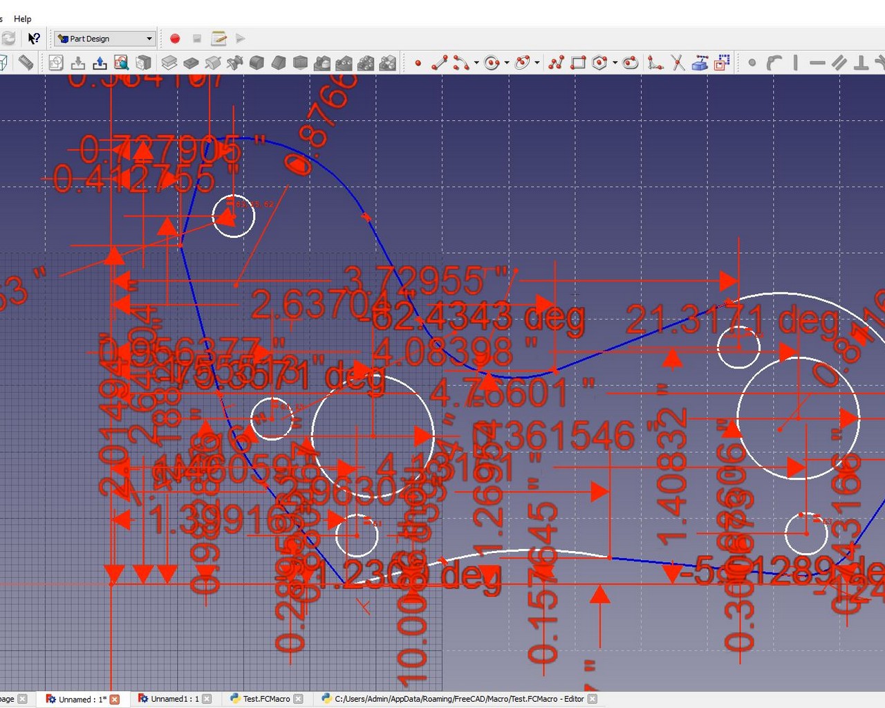
Figure 1: Figure with an elusive degree of freedom
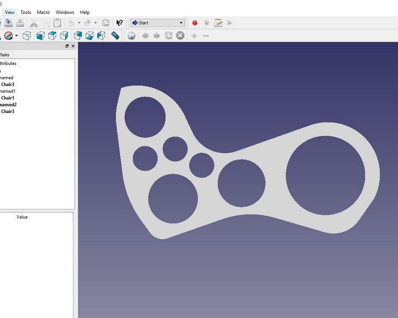
Figure 2a: 2D profile of the chaise lounge, as viewed in FreeCAD
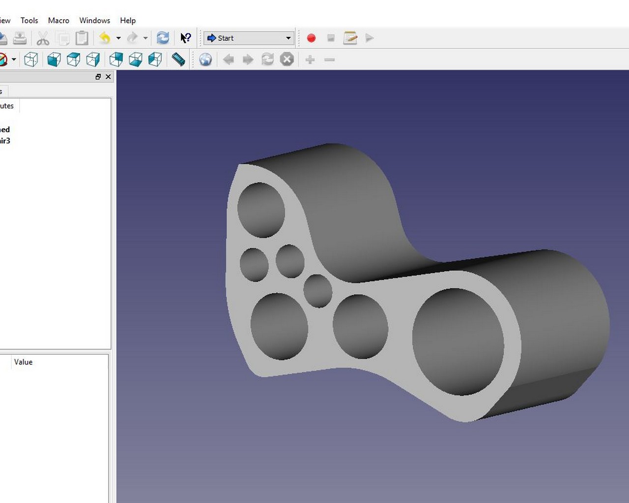
Figure 2b: 3D model of the chaise lounge, as viewed in FreeCAD
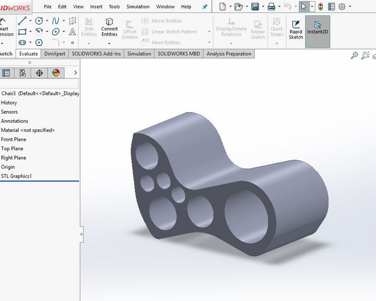
Figure 2c: 3D model of the chaise lounge, as viewed in SolidWorks
--Step 2: Slicing up the figure to create 2D shapes
I wanted to use a press-fit design to put the chaise lounge together, but also in an aesthetically pleasing manner. So I decided to slice the solid - tool of choice was 123D Make; also another free tool from AutoDesk. I looked at a variety of designs, as will be depicted in Figure 3 Below, but I ultimately decided on a design that will not take a significant amount of time to cut (or so I thought), and will also not use up a lot of material (or so I thought) 123D Make allows a variety of methods for slicing - Stacking, Crossfitting, Radial, and Circular. I was drawn to the radial design, and customized it to fit the 50in x 30in x 30in chaise lounge I was designing. This was going to take 6 OSB sheets in LAB, and about 104 parts to put together. It would be a puzzle, but the software also provides assembly instructions, so I decided to take on the challenge.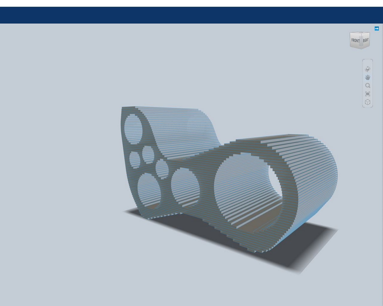
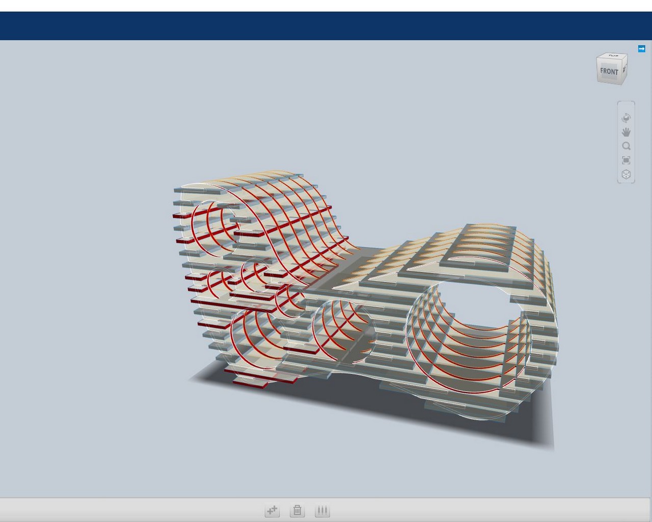
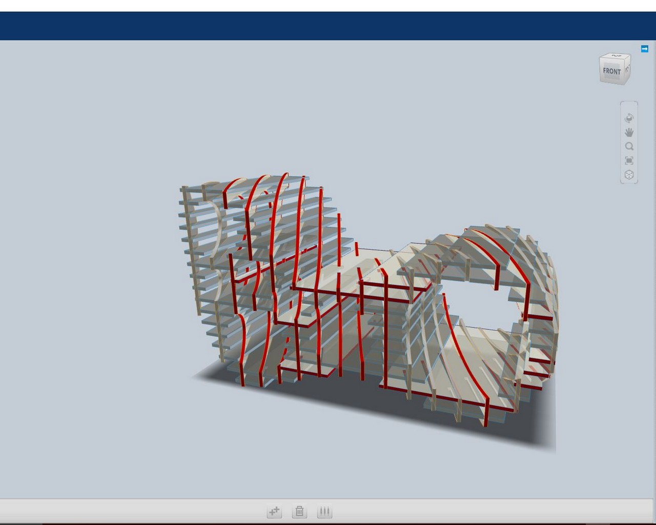
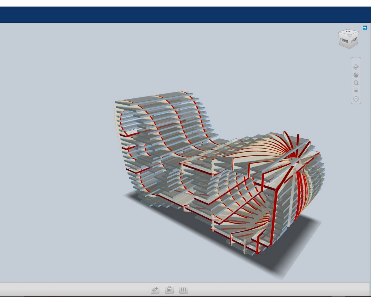
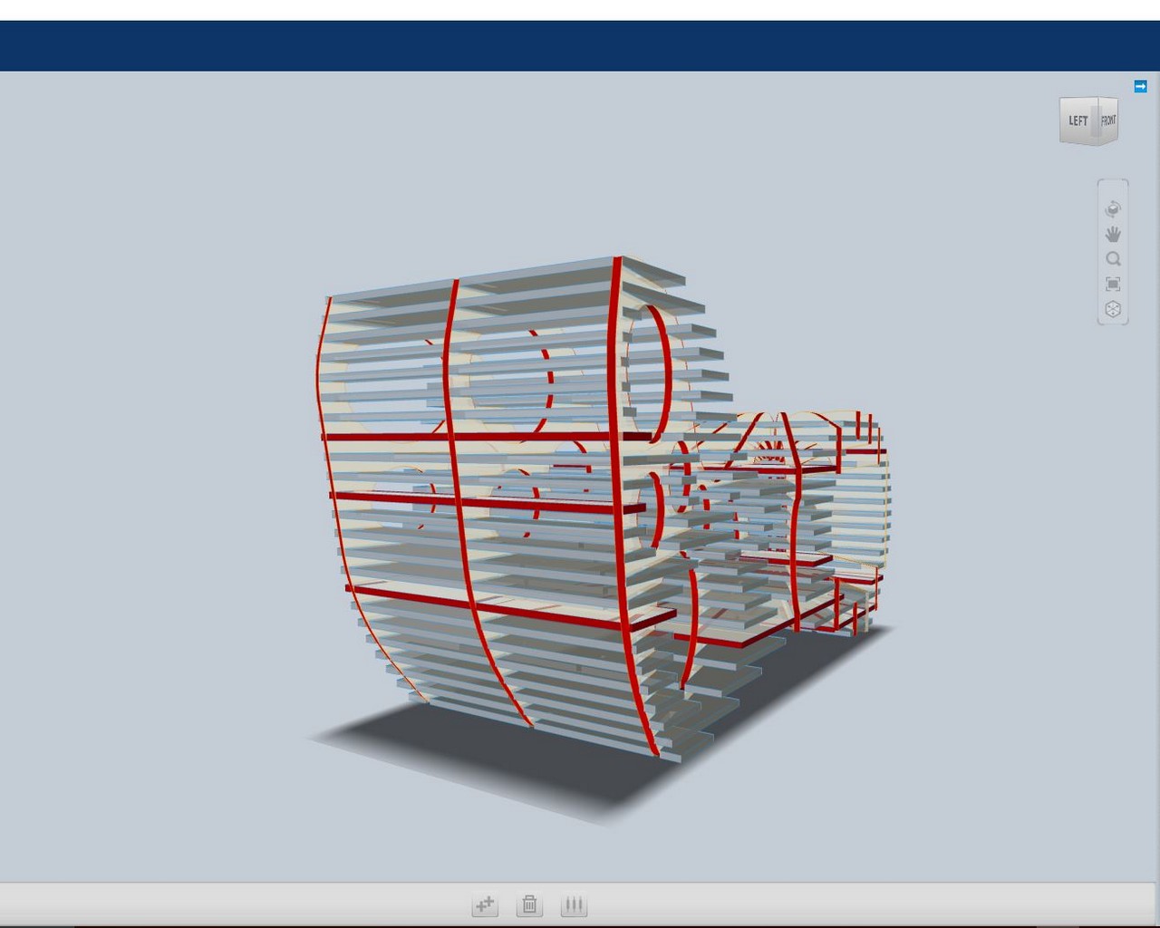
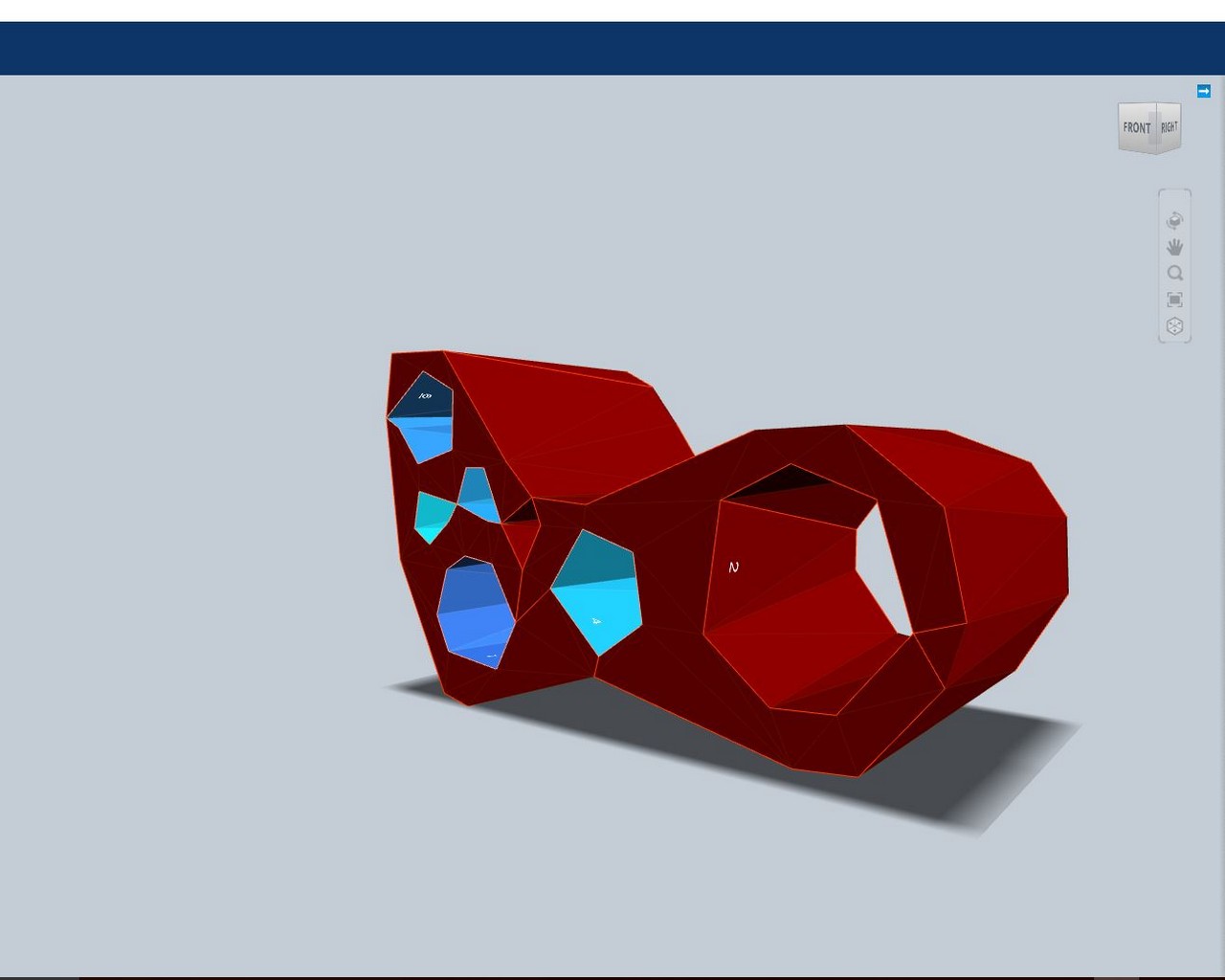
Figure 3: Different slicing options from 123D Make
(Stacked, Interlocked, Curved, Radial, Folded Panels)
It also became quickly apparent that I should scale the design down, in order to avoid the hassle of moving and placing 6 OSBs on the shopbot, as well as the extensive lenght of time I anticipated that it would take to cut the boards. As such, I scaled the design down to use only 2 boards. The design I ultimately chose, as well as the different sheet layouts to put the part together are depicted in Figure 4 below. 123D make also allows one to specify a number of parameters; for instance - tool diameter, board dimensions (length, width, and thickness) and margin sizes, and this is what it uses to determine how to slice the solid. One also has the option to select the density of the slicing, as well as an option to scale the design up or down, as needed.
There were some errors noted in 123D Make after the slicing, but after close inspection of the critical slices that make up the solid, I determined that I could feasibly go ahead with fabrication.
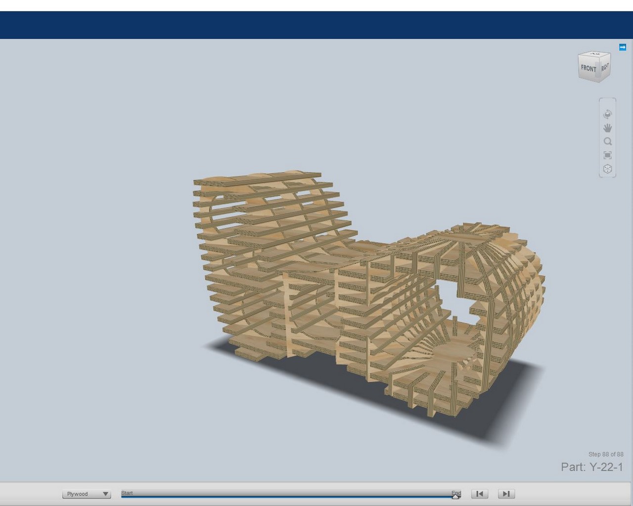
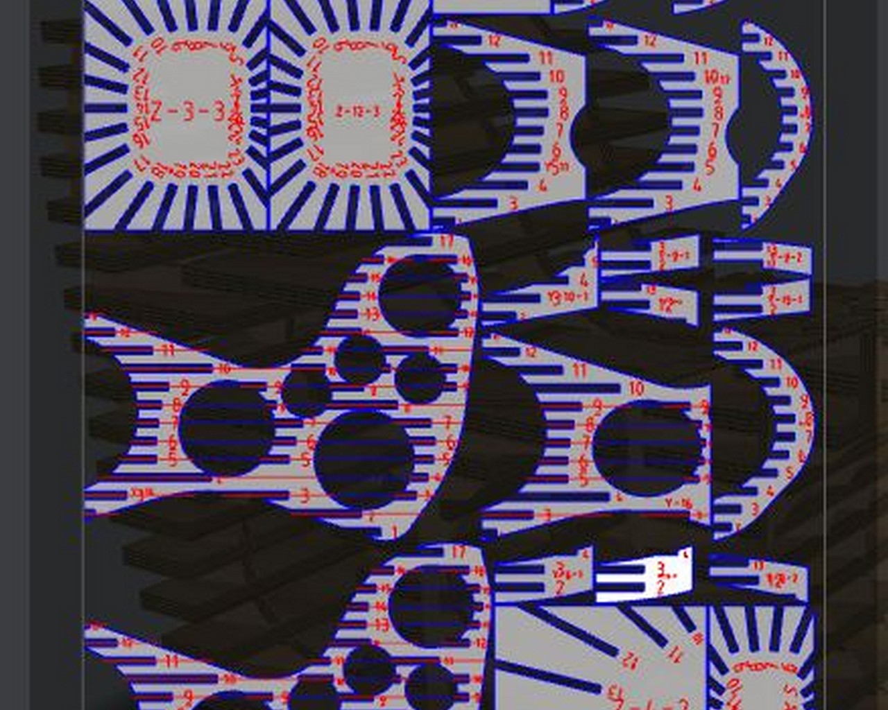
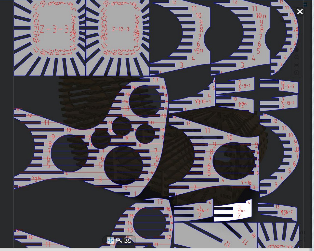
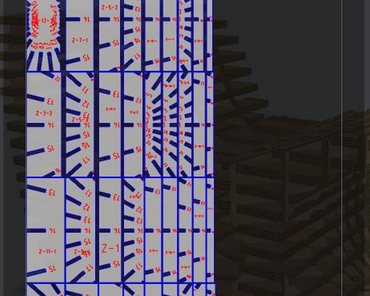
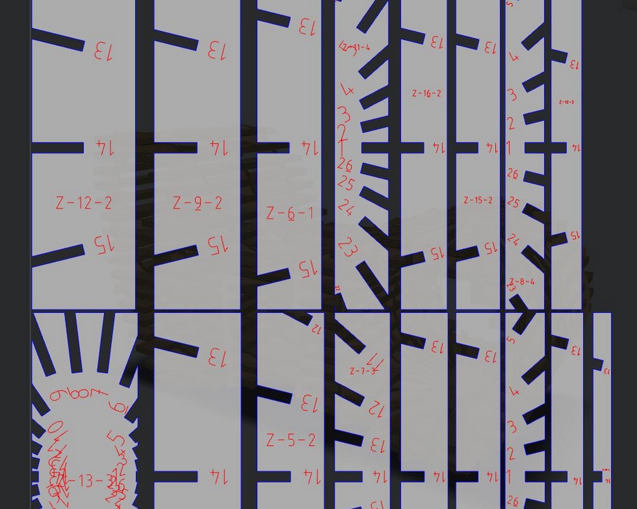
Figure 4: Chosen design for slicing, and the pages that make up the solid
--Step 3: Creating a vector diagram and the toolpath for the shopbot to cut
The vCarve software is the tool that we use in the lab to create the tool path, and this tool accepts PDFs or DXF file formats, so when I exported from 123D Make, I made sure to export in both formats. One thing that was a concern was the numbers printed on the individual 2D parts in the PDF, for which the vCarve would have created a toolpath. So I needed to edit the document and delete the numbers. I initially tried using SolidWorks to edit the file, but each number was represented as a bunch of points connected to form lines - no layers for letters or numbers, so the attempt to use this tool was a painstakingly long process. I eventually decided to use an actual vector tool (InkScape), and this helped dramatically, because the numbers and letters were in red, so I could select all objects that were stroked in that color, because the outline for the solid was stroked in blue. This worked very well. Figure 5 shows the solidworks attempt to delete the numbers, and Figure 6 shows the ultimate outcome from Inkscape.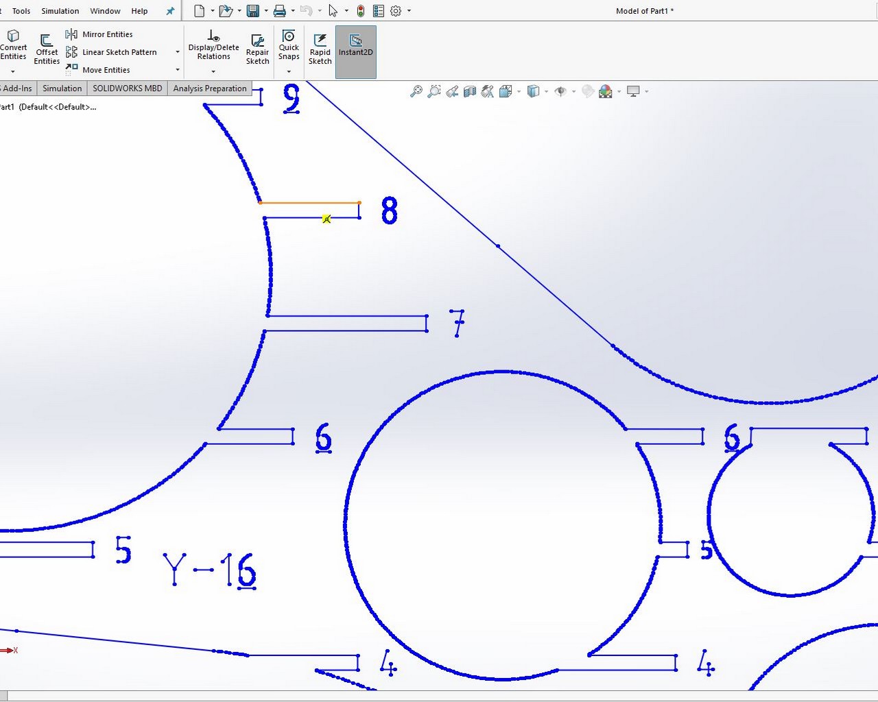
Figure 5: Solidworks attempt to delete the
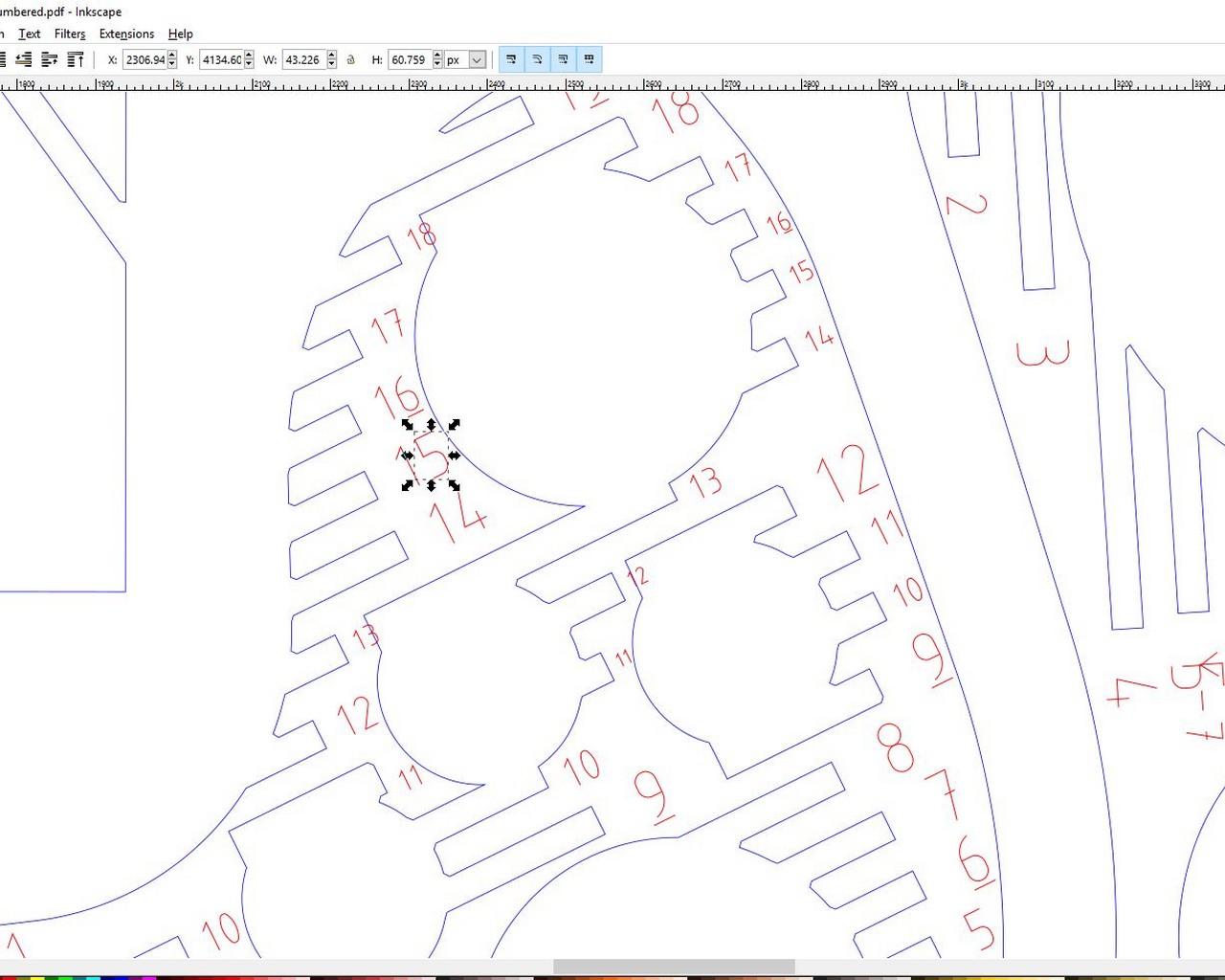
Figure 6: Solidworks attempt to delete the numbers
After editing the pdf file, I then imported the file into vCarve, where I then selected the interior features first, and then the exterior features, in that particular order. Set the parameters for the size of the OSB (96 x 48 x 0.44) on the X, Y, and Z axes respectively. For the Z, the thickness of the board varied along the length and width of the board, so I went with the thickness that was the largest measured with calipers.
I then saved the toolpath, for import into the shopbot software. After setting up the board, i.e placing it on the platform, and securing it down with screws, I attempted the cut. At this point, after the first interior feature was cut, it became apparent, that I had chosen the setting for Inside/Left, as opposed to Outside/Right in vCarve cut profile. The connecting tabs on my design needed to stay on the exterior pieces. Figure 7 shows the result of that mishap.
Also, during this cut session, I left the X,Y orientation as is, when I opened the file in vCarve (granted, with the appropriate dimensions), but the sheet was rotated 90 degrees from what the actual shopbot orientation was. This effect of this is also depicted in Figure 7 (cutting past the margin - and this is one main thing that prompted stopping the machine). The ideal thing to do, which I quickly realized, was to create a new sheet in vCarve, with the dimensions of the board (this will be in the proper orientation), then import the vector diagrams into the newly created sheet, and rotate to fit the sheet accordingly. This then allowed me to test the new "Inside/Left" cut profile at the appropriate location on the board, without needing to change boards. I could have also Zeored the X and Y axes further up the board and that would have worked for the test profile cut. But for correctness, I needed to rotate the import to fit the physical board.
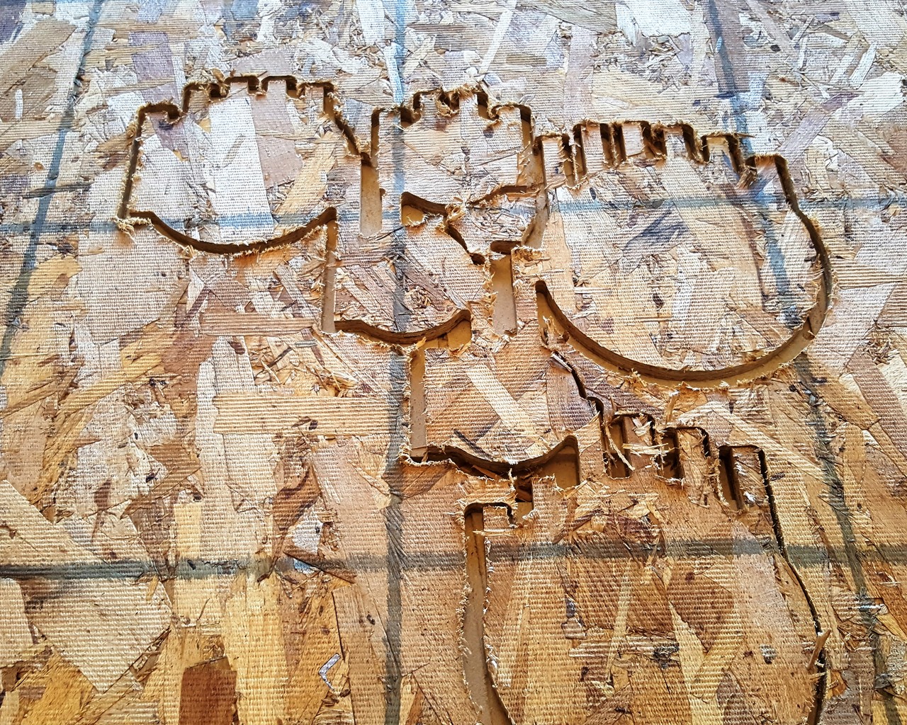
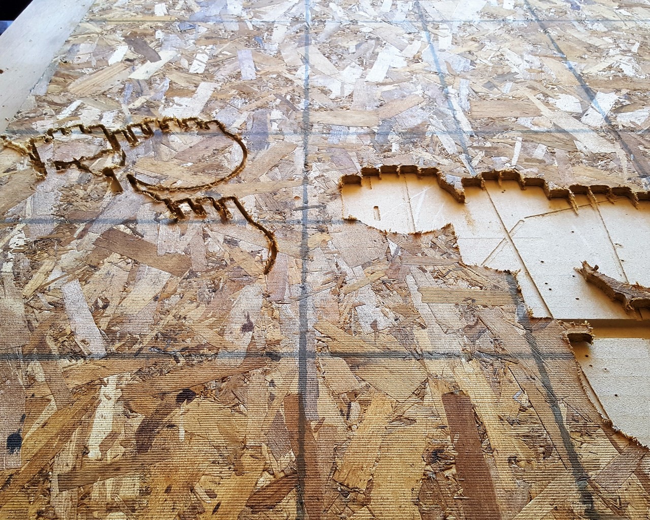
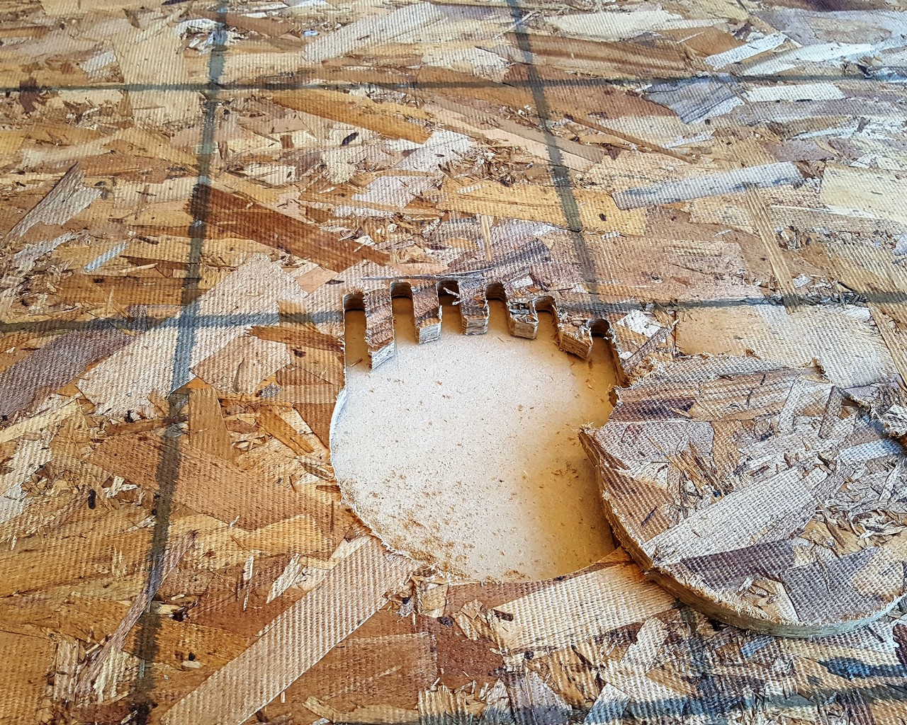
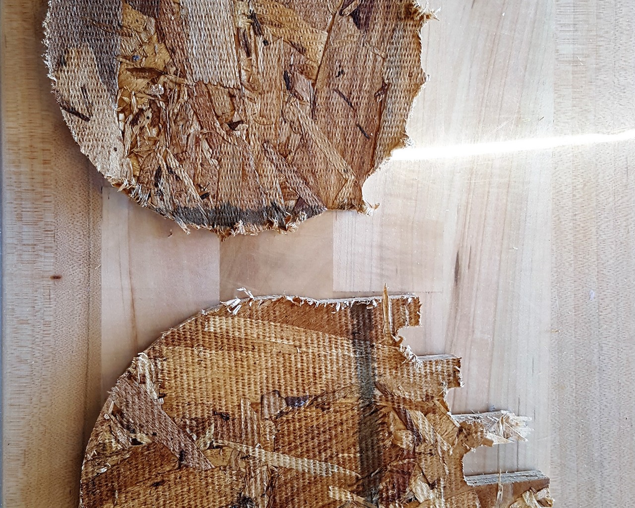
Figure 7: Different cut methods producing different results.
Now, in the intrest of time, and paying attention to what had already elapsed, I decided to scale the design down even further to use only 1 board, and to also use the interlock slicing method, because vCarve initially indicated that it would take approximately 4 hours per board to cut each board for the initial 2 board, radial slice design - No one has that kind of time! After going through the processes mentioned above for the newly scaled down process, we determined that someone had changed the travel speed of the shopbot, and made it slower. But I had already committed to this new design, so this is what I ultimately went with.
Considering the issues a lot of people experienced in the EECS section, with this cutting process, I am yet to cut my part.
Update: Actual Cutting!!
Gavin (The EECS TA) was able to provide me with some time at the IDC lab, so I could cut my board. This was after troubleshooting the shopbot computer and determining that the cutting tool parameters were changed for a tool with a slower feed rate assigned to it - although, we needed to restart the computer for the reverted settings to take effect. I was able to successfully do my cutting and assembly! Figure 8 (a thru d) depicts these steps.
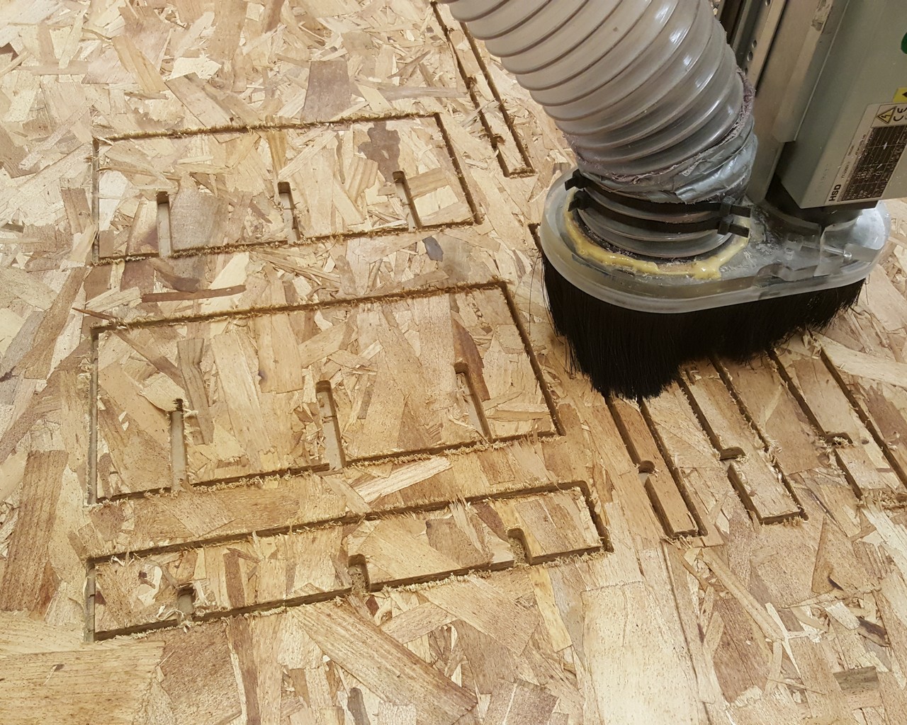
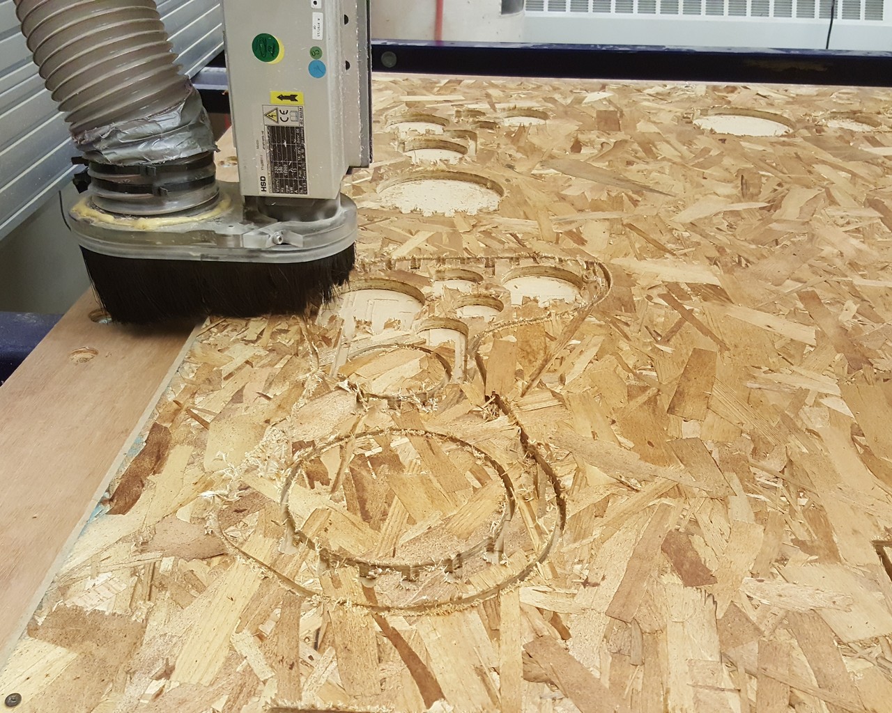
Figure 8a: Cutting.... Finally! I needed to label these parts, to make assembly easy
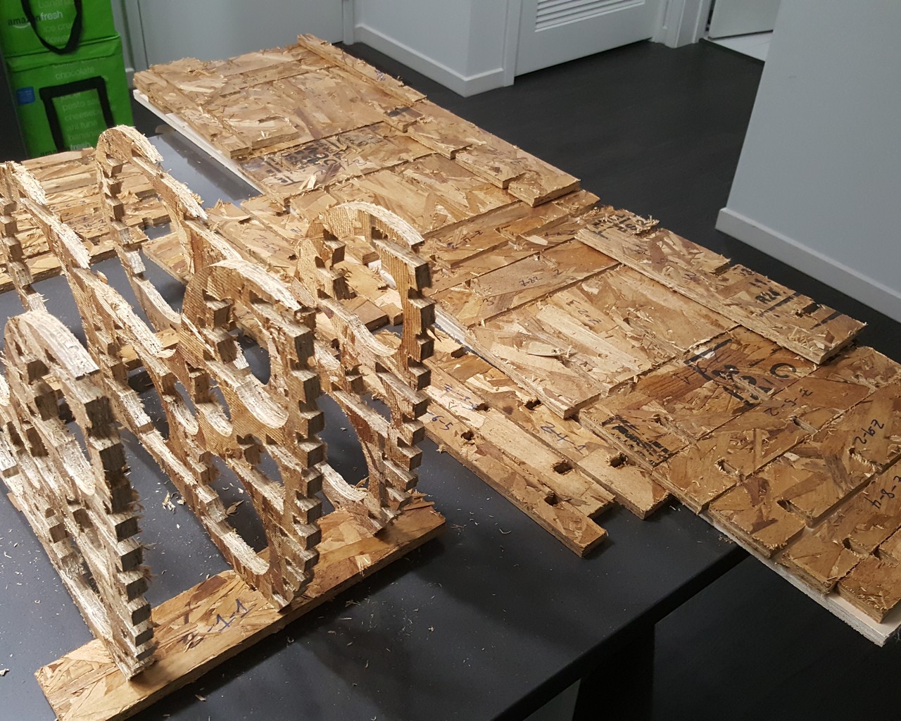
Figure 8b: Assembly
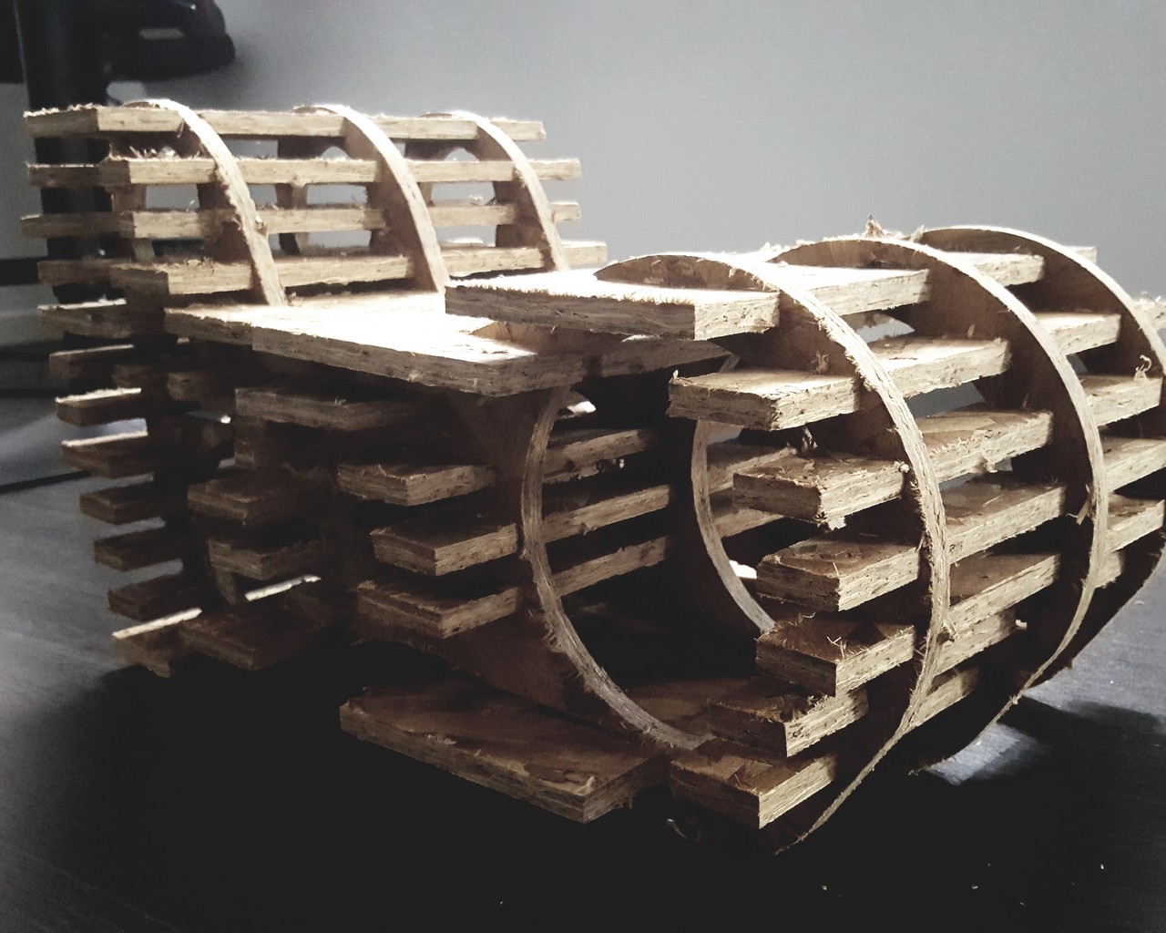
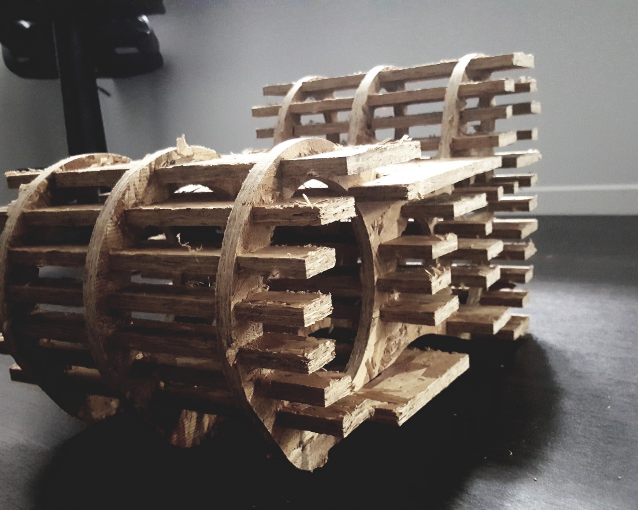
Figure 8c: Finished Product (Angled View)
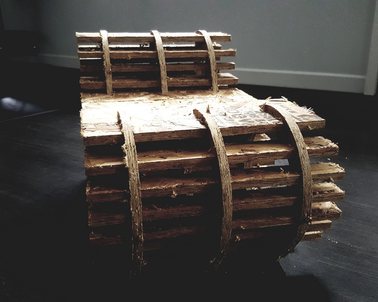
Figure 8d: Finished Product (Front View)
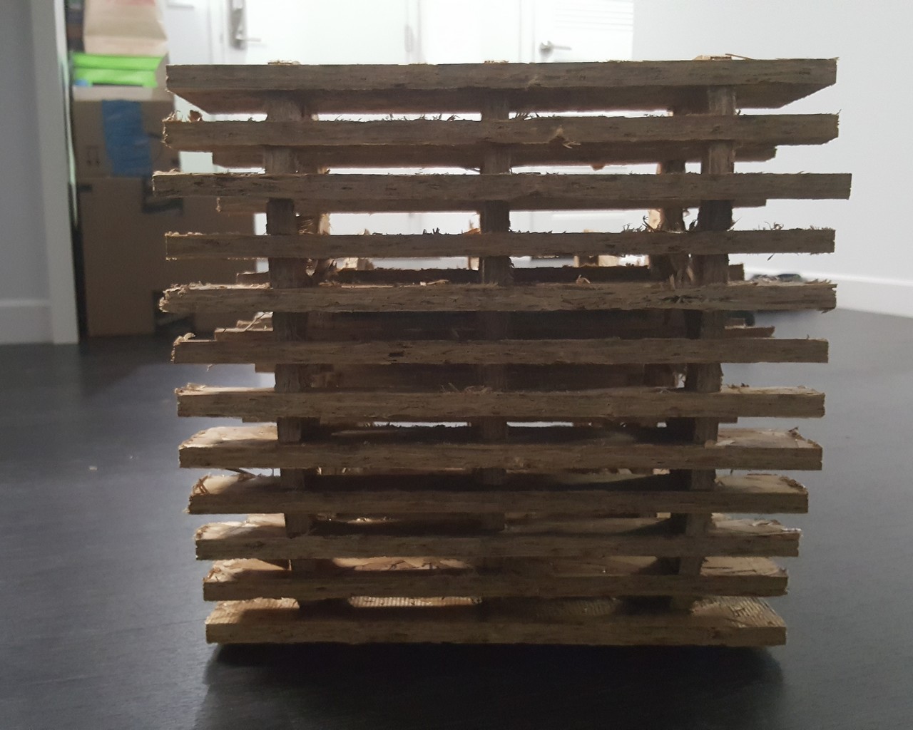
Figure 8d: Finished Product (Back View)
One thing to note is that because of the progressive scaling down of the design, to allow for faster cutting, and the fact that the slicing was board-thickness constrained, the physical product at the end looked more pixlated than I would have liked - some of the curved surfaces ended up appearing flat. But at larger scale, these facet issues would be resolved, at the expense of more time to cut, that is. Also, I was very impressed by the rigidity of the chaise, even at such a much reduced scale. I fully intend on scaling this up at a later time, doing the radial slicing, and using better wood, to get a full (yes, 6 sheet) version of this design.
That said, I really enjoyed the end-to-end process, and look forward to more computer-controlled cutting.