--How to Make (Almost) Anything--
--Week 10--
--Composites--
--Step 1: 3D Modeling and slicing in SolidWorks and 123DMake
I wanted to use this week to create the bicycle helmet that will be used for my final project, so my initial attempt was to design a helmet from scratch using solid works. This proved to be more involved than I initially thought, and I decided to look for a template of already existing helmet designs on the web (www.grabcad.com). This was with the hope that I will at some point be able to use this template and add modifications (inset locations for electronics and lights). For this week, it would be enough to just 3-axis machine the solid, and then use that to create the composite from burlap fabric and an epoxy mix.I then used 123DMake to scale the solid to fit withing a 16 cubic inch volume, and sliced the solid using the 3D method to be able to fit 5 (20 X 20 X 2) inch sheets of foam - the foot print that was allowed on the shopbot in the EECS lab. There were four STL mesh slices. These would then be run through "Cut3D" to creat a 3-axis machine tool path for each individual slice. The following figure 1 is a depiciton of the design in SolidWorks, and the slicing outcome from 123DMake.
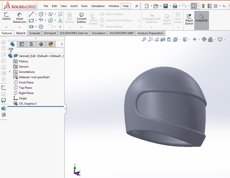
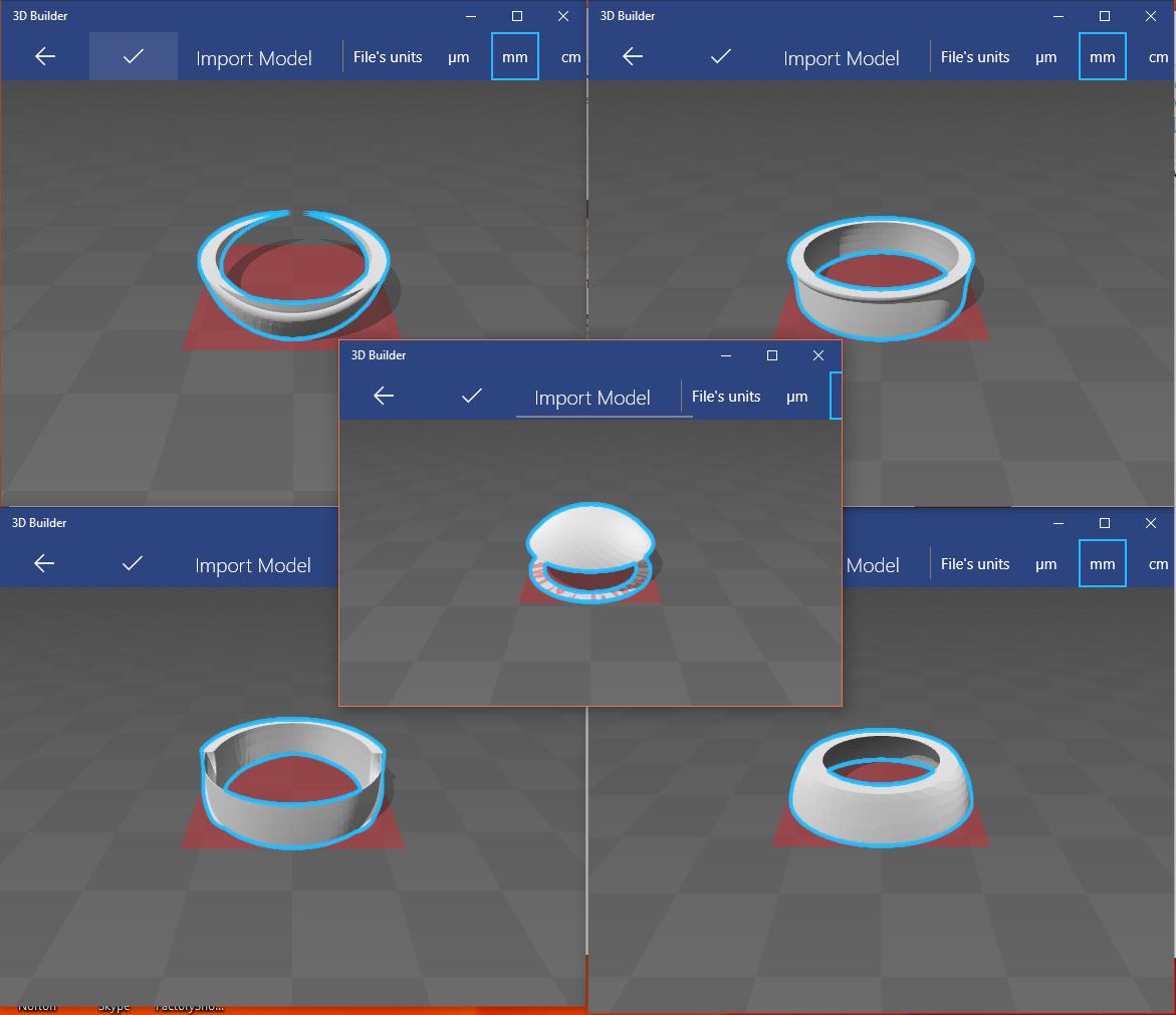
Figure 1: Helmet design and slicing
It was going to take about 4 hours to machine the part on all four sheets, so in the interest of time, and respect for everyone else who needed to use the shopbot this week, I decided to go with an easier design that would fit on a single 20 X 20 X 2 sheet. At this point, scaling the helmet down to fit just one sheet would not be a beneficial exercise, so I decided to go with a food tray - simple enough, and this is something I actually need. The point here is to get the process of creating composites down, processed, and documented. This design would allow for that. Figure 2 is a depicition of the SolidWorks design of the food tray. There was no slicing needed for this
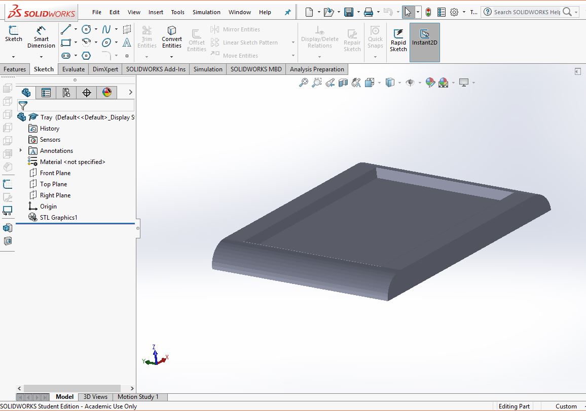
Figure 2: Food tray design
--Step 2: Milling and layering to create the composite
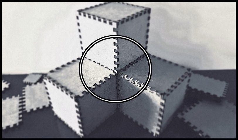
Created the 3-axis machining tool paths, and used the settings for the foam in the lab to set up the cut. Followed the same process as with the shopbot week for "make something big", to cut the foam. Cut the burlap, cut some foil, and cut the breather and the bleeder layers to fit the mold. Mixed the epoxy (2.1 to 1 - A to B ration) to coat 4 layers of the burlap. After coating the layers of burlap, placed some foil on the mold, and sprayed some easyoff on the foil (this will allow for an easy removal of the composite from the foil). I then the placed the layers of the coated burlap on, then placed the bleeder and the breather layers, and then placed everything in a vaccum bag. Created a vaccum, and waited for four hours for the process to cure.After curing was done, I took the part out, and took off all the different layers to reveal the finished composite. Figure 3 is a depiction of the process described in this step. One thing to note, the process of taking the layers off was not as easy as I had expected it to be, the breather and bleeder layers were stuck pretty tightly to the composite. Perhaps the vaccum was too tightly formed. I'll determine this once I run through this again for my helmet design.
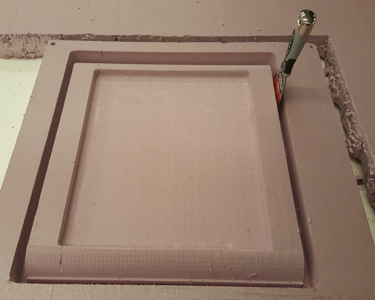
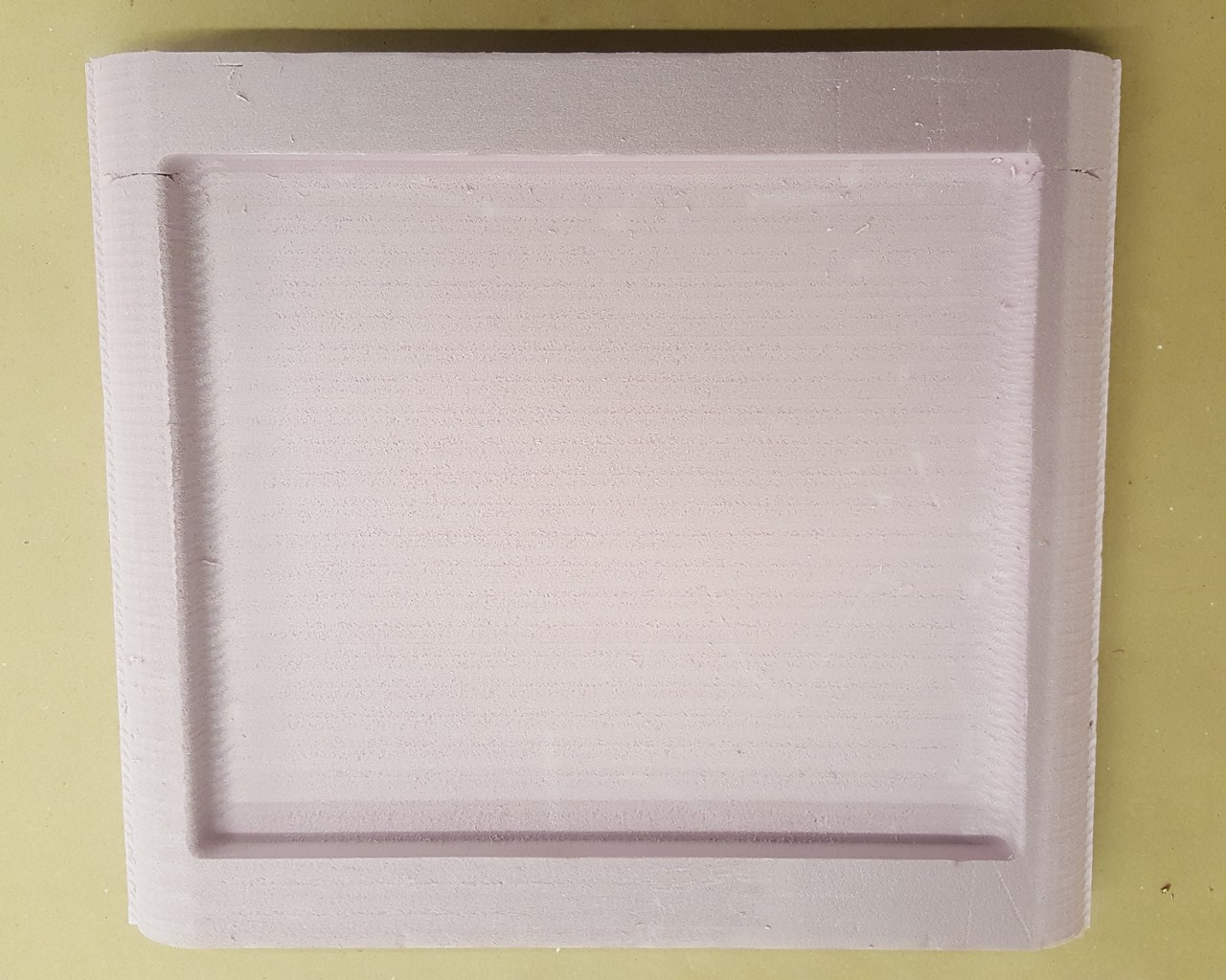
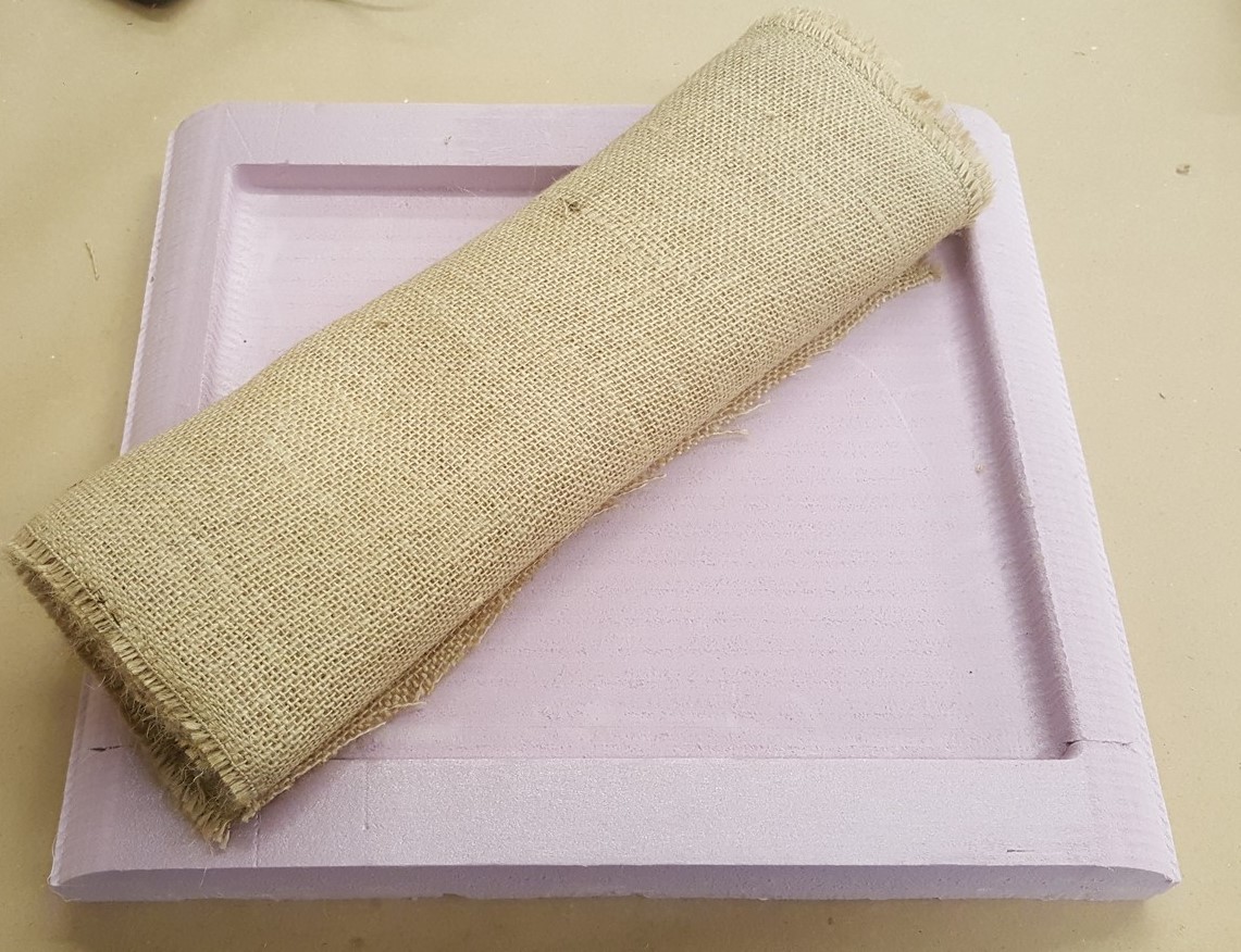
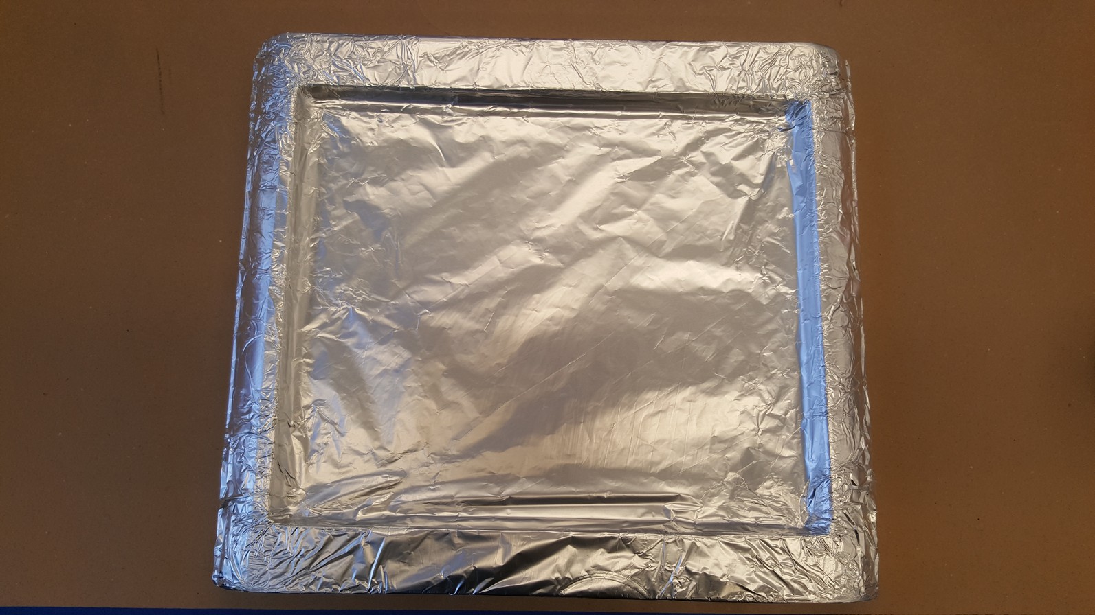
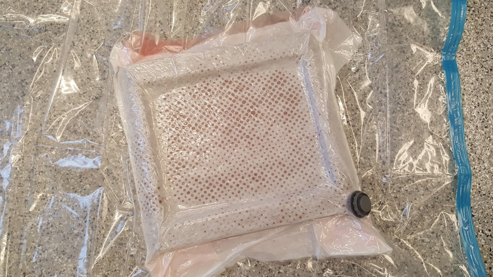
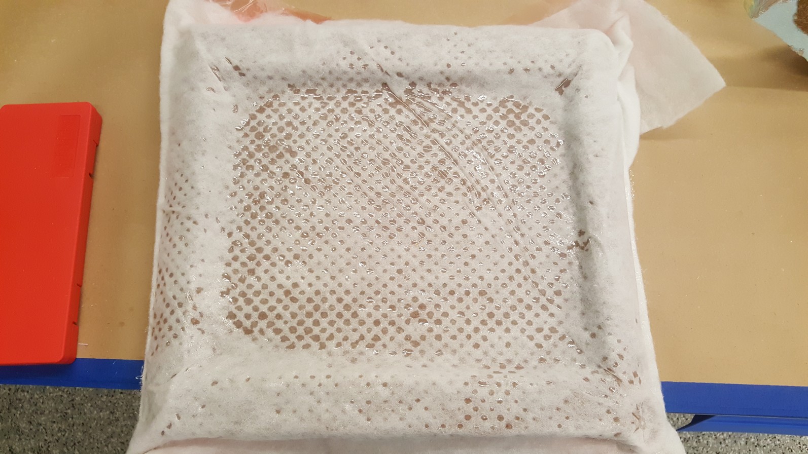
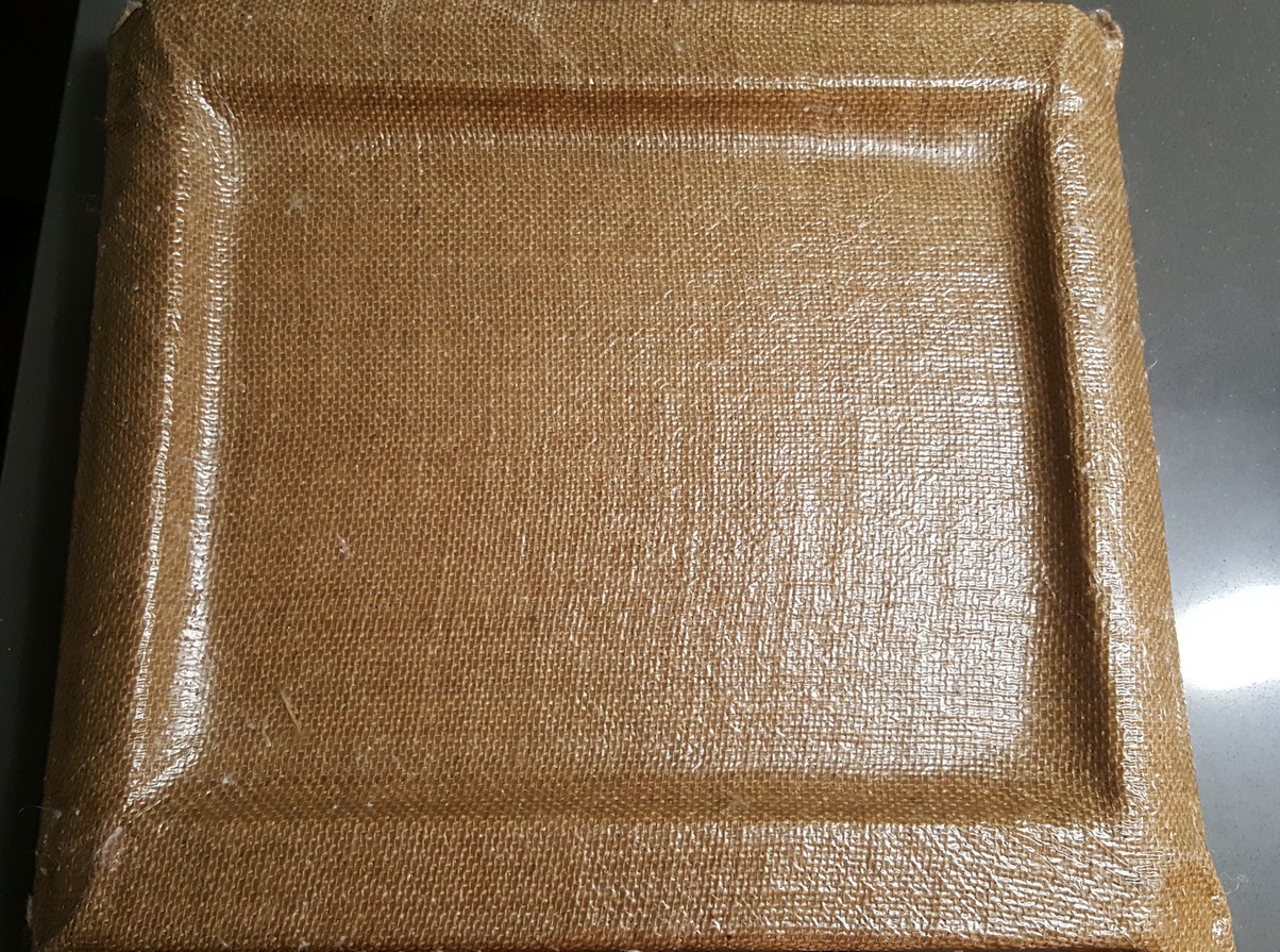
Figure 3: Creating the composite