--How to Make (Almost) Anything--
--Week 11--
--Output Devices--
--Step 1: Designing the board in Eagle
This week, my goal was to further develop my final project idea, and test the output functionality of the Atmega328 IC, because this is what I intend on using in my final project design. I designed a breakout board for the 328 chip to let me interchange peripherals on the fly (in the spirit of rapid prototyping, as defined by this FAB class). This board has power and ground pins exposed for other boards to tie to. I also designed a breakout board for the accelerometer with a few LEDs embedded on them. The process is meant to be in two stages. The first stage is to turn on an LED tied to port PB5 on the 328 breakout board, based on a treshold level on the ADC pins that the accelerometer board is connected to. Stage two involves turning on the LEDs on the accelerometer board based on the input sent to 328 IC, and then output levels on the output pins from the 328 board, tied to the LEDs on the accelerometer board. The following figures depicts the board design for both the 328 breakout board and the accelerometer board.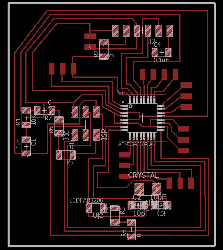
Figure 1: Atmega 328 breakout board design
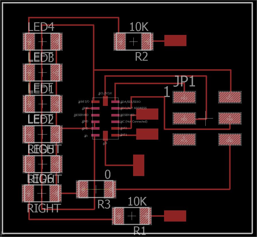
Figure 2: Accelerometer board design
The export, milling, and stuffing processes were similar to steps that had been taken in previous weeks, so I will spare those details here, because nothing particularly interesting took place.
--Step 2: programming and testing the boards
Most of the work done for this week was focused on step 1 as described above, with some attempts at step 2 that did not provide any valuable results. I was able to successfully employ a program (Pieced together from a variety of sources, with some editing) that would sense a level change in the output from the accelerometer board, and then use that value change to turn on an LED. However, when it came down to turning on the LEDs on the accelerometer board itself, I was unable (thus far) to get those to turn on under any conditions. I am uncertain if this has to deal with my board design, or some fault in my programming (I2C protocol I want to implement here) - but with further digging, I should be able to determine the root cause, and mitigate the issue I am experiencing. The following Figure 3 is an excerpt of code used to implement step 1.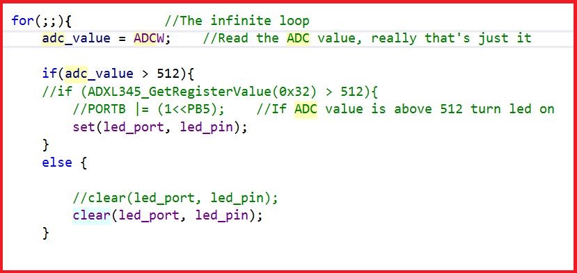
Figure 3: Milled Board
The following is a video illustration of the program in practice.