--How to Make (Almost) Anything--
--Week 12--
--Interfaces and application programming--
--Step 1: Finding a suitable interface
Thus far, I have been struggling with getting I2C or SPI to work on my Atmega328 board to communicate with any peripherals (particularily, with my accelerometer expansion board). I decided to use this week to explore a different programming interface or environment, i.e. the Arduino IDE. Considering that up to this point, I have been programming directly in C, and using Atmel studio to do all of my programming via Windows 10, I wanted to explore a different option. This way I can hopefully determine that the Atmel studio, and its associated "Terminal" extension are not the reasons why my communication protocols don't seem to be working properly.The abstraction that the Arduino IDE offers, typically works with standard boards that are made specifically for the IDE. That said, the core of some of these off the shelf boards is the Atmega328p IC - especially the Arduino pro and the Arduino pro mini boards - so I looked to "back-map" behind the abstraction layer, in order to see what pins are connected to what abstractions in the IDE. This way, I can easily communicate with my board.
Lucklily I came across the arduino pro mini board annotation pdf document, and this was very helpful in understanding pin connections on the 328 IC and how it relates to the IDE. Figure 1 is an excerpt from this document, particularly showing the IC itself.
.
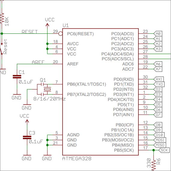
Figure 1: Final board design from eagle
--Step 2: Setting up the interface and programming
To work with the interface, a few things needed to be selected - first, the programmer "USBTinyISP" needed to be selected from the "Tools" menu, then the Board: "Arduino Pro or Pro Mini", then ensure that the processor "Atmega328 (5V 16MHz)" is also selected. Figure 2 depicts this process.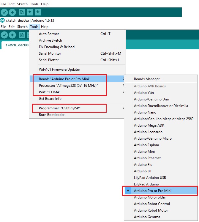
Figure 2: Selecting appropriate settings to program in the interface
When the right program is selected, the next step is to write the program to be loaded onto the board. The Arduino IDE does have some sample programs, I was was able to find ones that were written for the Pro or Pro Mini board and cherry pick items to create the "sketch" that will be loaded to the IC. The following Figure 3 is an excerpt of this code.
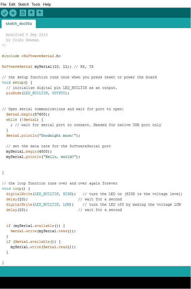
Figure 3: Excerpt of code for the Arduino IDE
When the code runs, the delay in the "loop" function does not seem to match physical timing accurately - For instance, one would assume that 250 refers to 250 milliseconds, but unfortunately there is a factor multiplied to this number to cause it to mean a different interval of time, and I am yet to determine what this factor of multiplication is. The video below shows different delays and the effect on the board. All we are doing here is turning an LED on and off. There is also code to send data to the serial port, in this case via COM4 - however, all that we get in the serial monitor is garbage values
I need to further investigate why my serial communication continues to be non-functioning. At least, in this case I see some data being transmitted, albeit garbage data.