Chika Makes Things 2016
Week 9: Input Devices
Goal: Add a sensor to a microcontroller board that you have designed and read it.
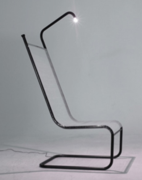
One feature that I want to incorporate into my final project plan of fabricating an ergonomic chair, is a lamp that turns off when ambient light diminishes. I am invisioning a design similar to the one shown below.
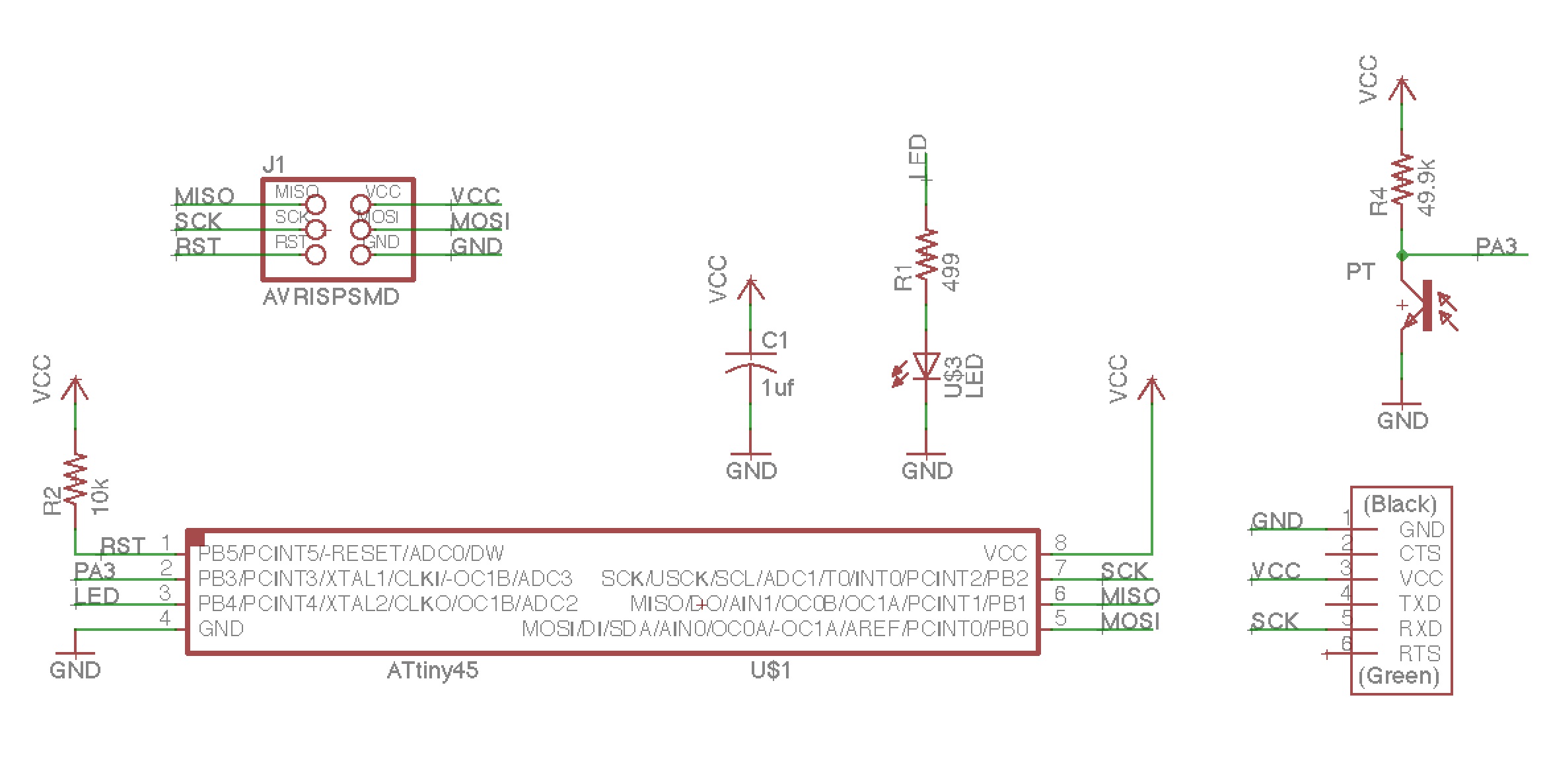
 I was happy to find a pcb designed by Keith Tan in a previous year that incorporated the main components needed for this idea: phototransistor and LED. The board is a simple extension of Neil's Phototransistor example board by adding an additional resistor and LED. Here is the list of components used:
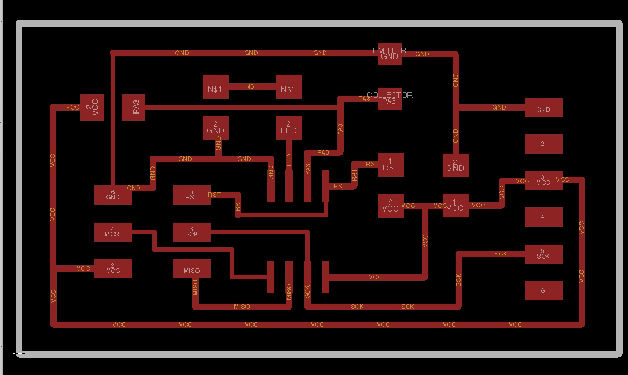 After exporting the board, designed in Eagle, at 600dpi and checking Monochrome, I imported the png into fab mods. I made sure to multiply the dpi by 2 as recommended for Retina displays.
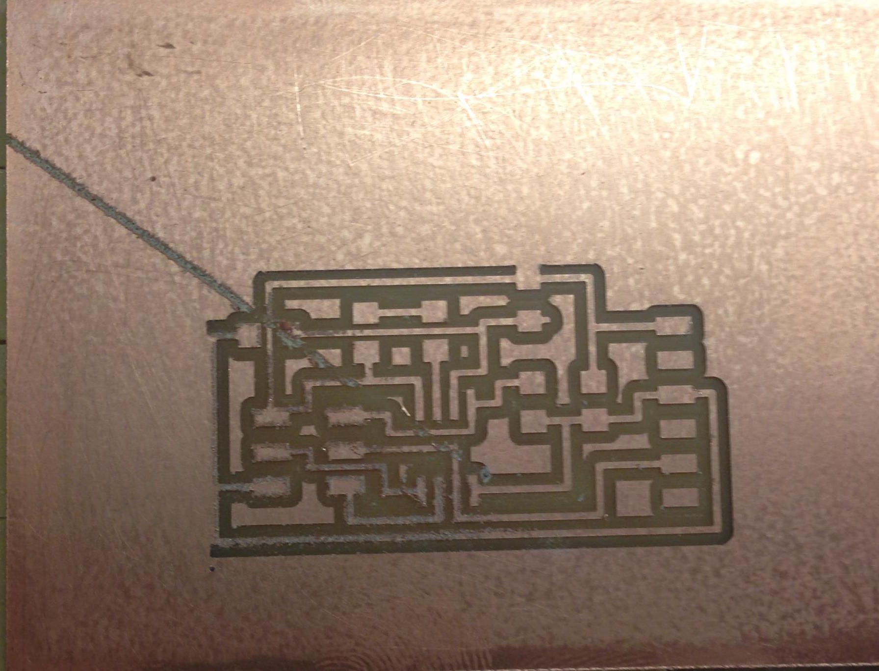
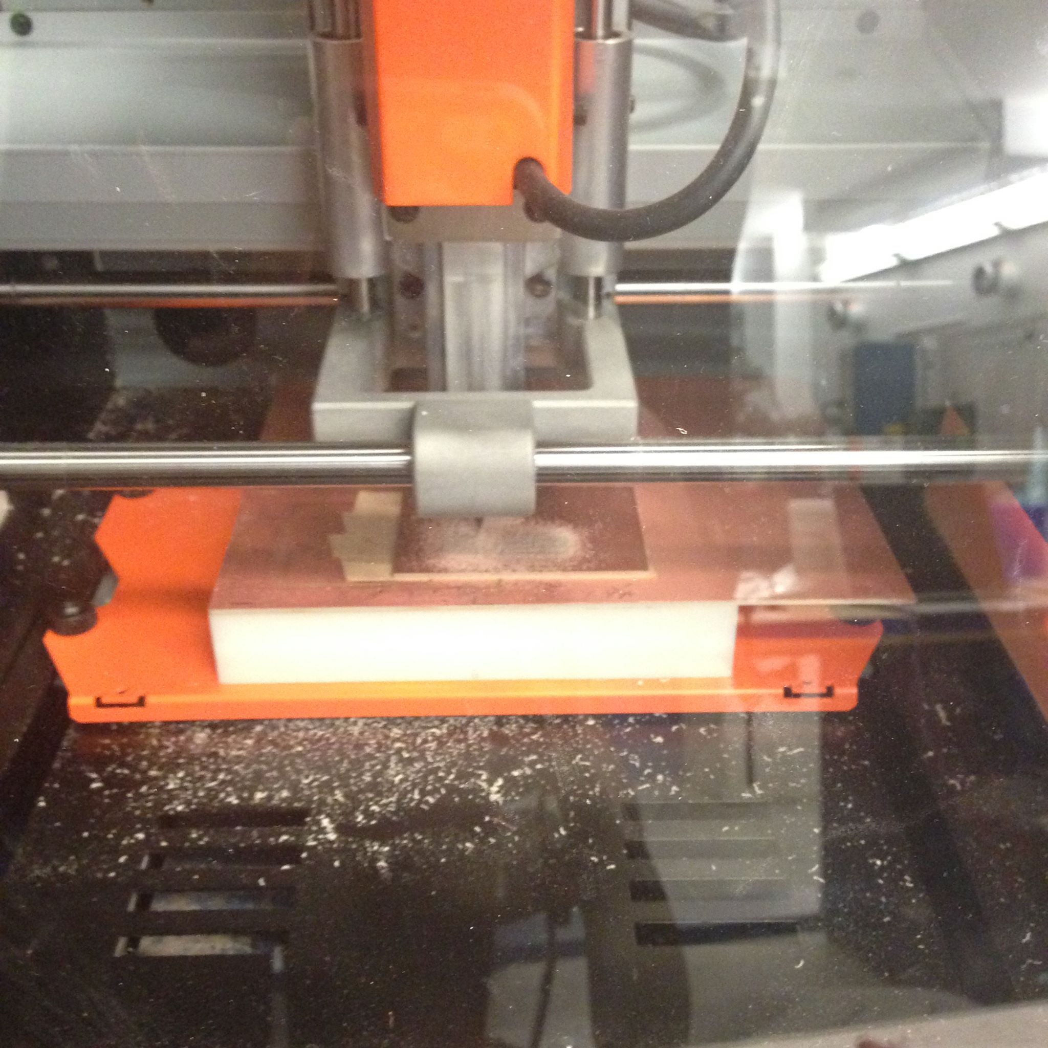 The milling went somewhat smoothly. I had a slight hiccup due to forgetting to check that the home z value was higher than the origin height. This mistake resulted in the bit dragging across the board at the end of the job.
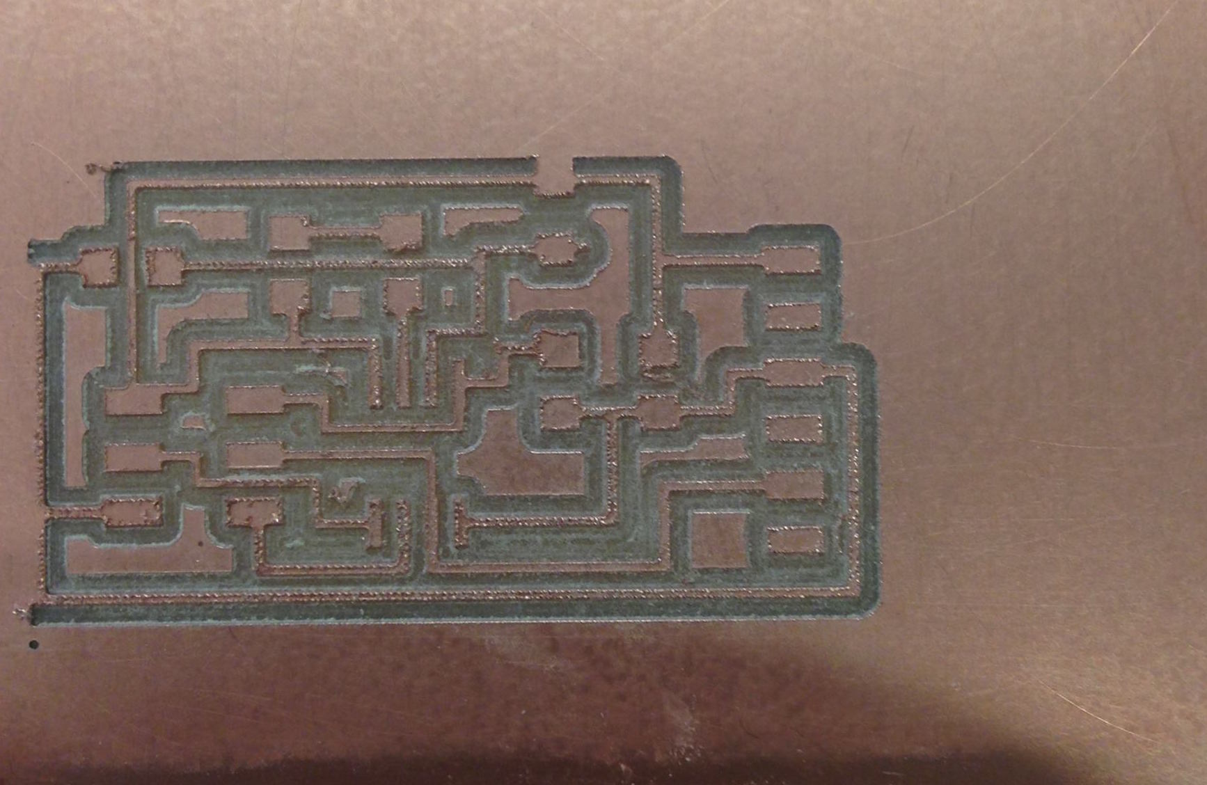
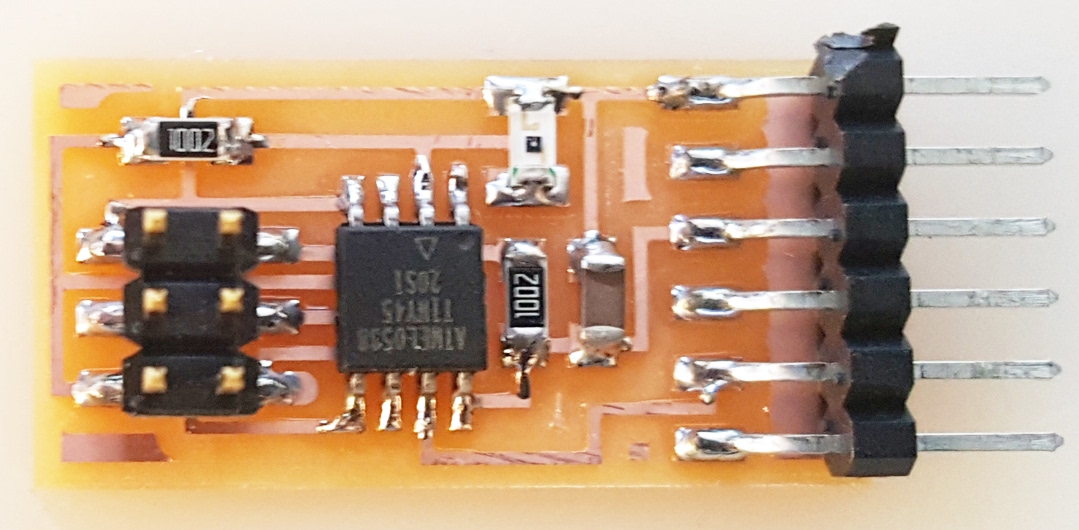
 Here is an image of the corrected board.
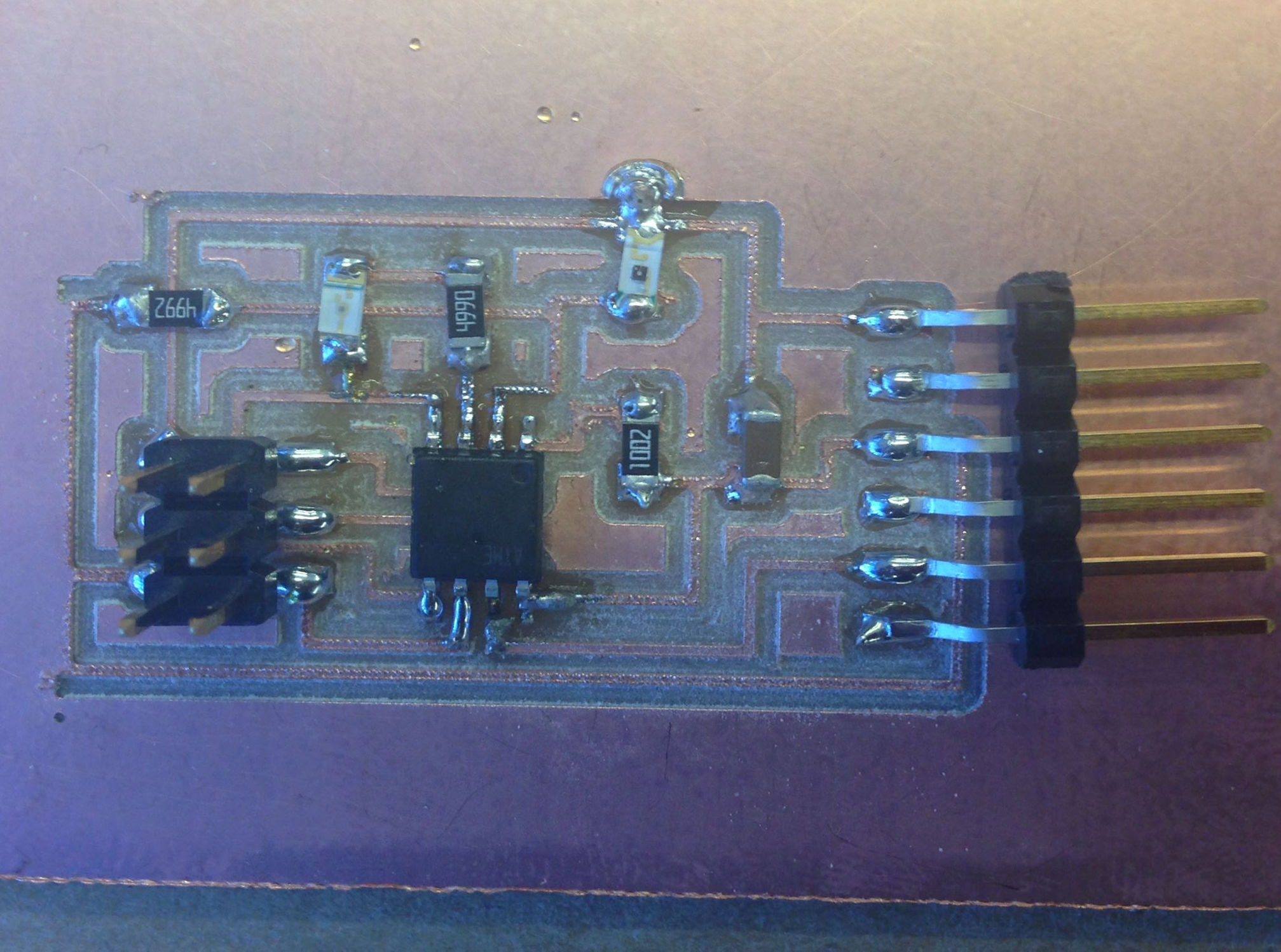
 I soldered all of the components, but quickly noticed a short caused by an overflowing blob of solder next to the phototransistor. To correct this, I used the copper wire to remove excess solder and then an exacto knife to ensure that the 2 traces were completely seperate.
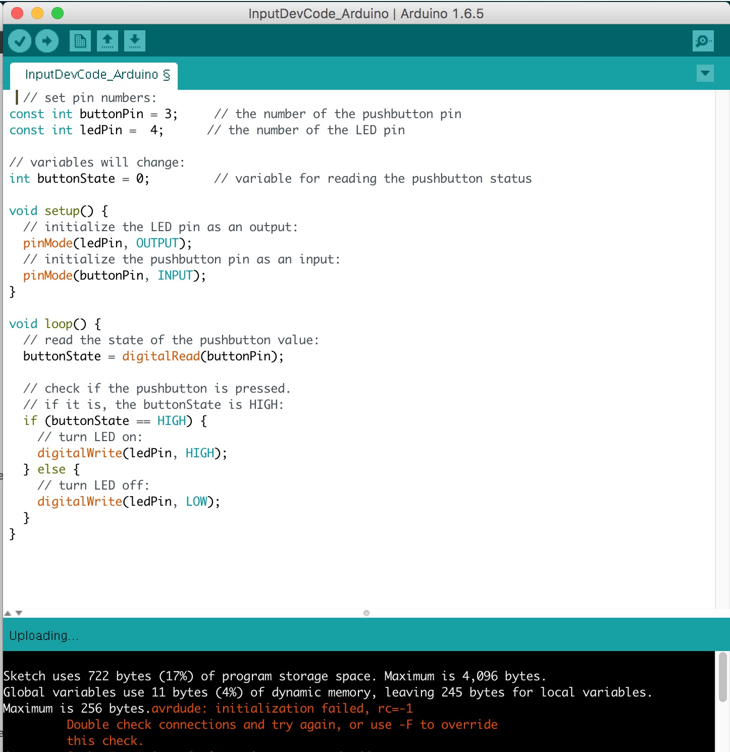
 What came next was puzzling. I checked all of the connections to VCC and GND and between components with a multimeter to ensure that no other unexpected connections were made. I also double checked the orientation of the applicable components: LED, photransistor, and Attiny45. When I attempted to power the board with the FTDI cable connected to my laptop, the AVRISP I was using for programming flashed green, indicating that the board was indeed receiving power. Even after all of these checks, I received the dreaded and vague arduino error when trying to run my program below: "avrdude: initialization failed, rc=-1. Double check connections and try again". The goal of the program is to turn off the LED when the phototransistor is obscured.
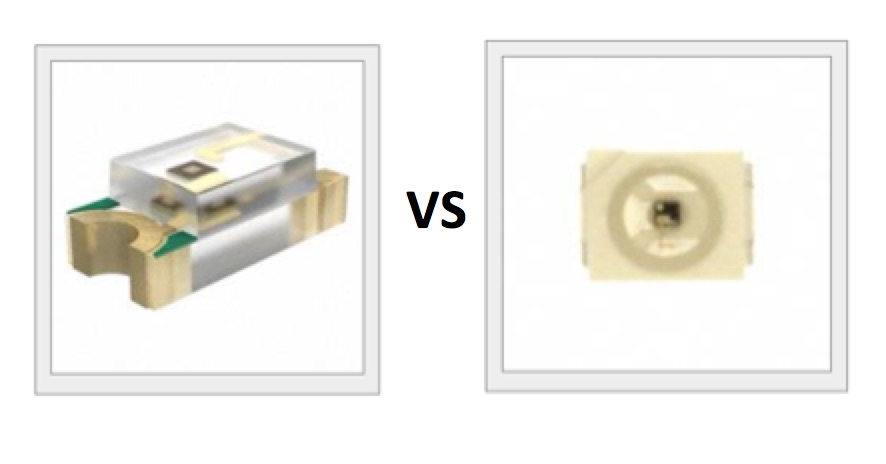
 One idea that I have is that I may have accidentally used the wrong phototransistor. I could only find the one shown on the left in my lab section, but it appears that Keith used the one on the right for his design. I am still working to understand the differences between them and what that might mean for functionality of the pcb:
ATtiny45
Resistor 10K
Resistor 49.9K
Resistor 499
Capacitor 1 uF
HDR 2x3
FDTI HDR
LED Red
SM/Phototransistor: NPN 1206