week 01 // computer controlled-cutting
For this week's assignment, we explored rapid prototyping with laser and vinyl cutters. We began with a group assignment to determine the best settings on the laser cutter for a cardboard to press-fit well together. Then, we used what we learned to design a laser-cut press-fit construction kit. Finally, we used the vinyl cutter to make anything we wanted.
01.01 // group laser cut test
For this week's assginement, we had to make a press-fit laser cut construction kit as well as learn how to use the vinyl cutter. First, as a group, make laser cut test parts by varying cutting settings and slot dimensions. We received a cardboard sheet that was approximately 0.177" thick. Then, using Corel Draw (the software that the laser cutter can read), we made squares with slots varying in increments of 0.005" from 0.177" to 0.137". The slots were created by drawing rectangles of a specific width and using the "Back minus front" tool. To make comparing dimensions easier, we also engraved the dimension of each slot on the pieces.
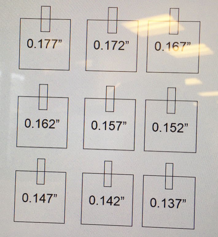
// using coreldraw to lay out squares of various slot dimenions //
From there, we used the Universal Laser Cutter toolbox to try a few power and speed settings both for the vector and raster cuts. We wanted to achieve a complete cut through our cardboard and readable engravings, but we did not want to char the mateiral at all. In the end, we settled on 60% power and 7% speed for vector cuts and 45% power and 100% speed for rasters.
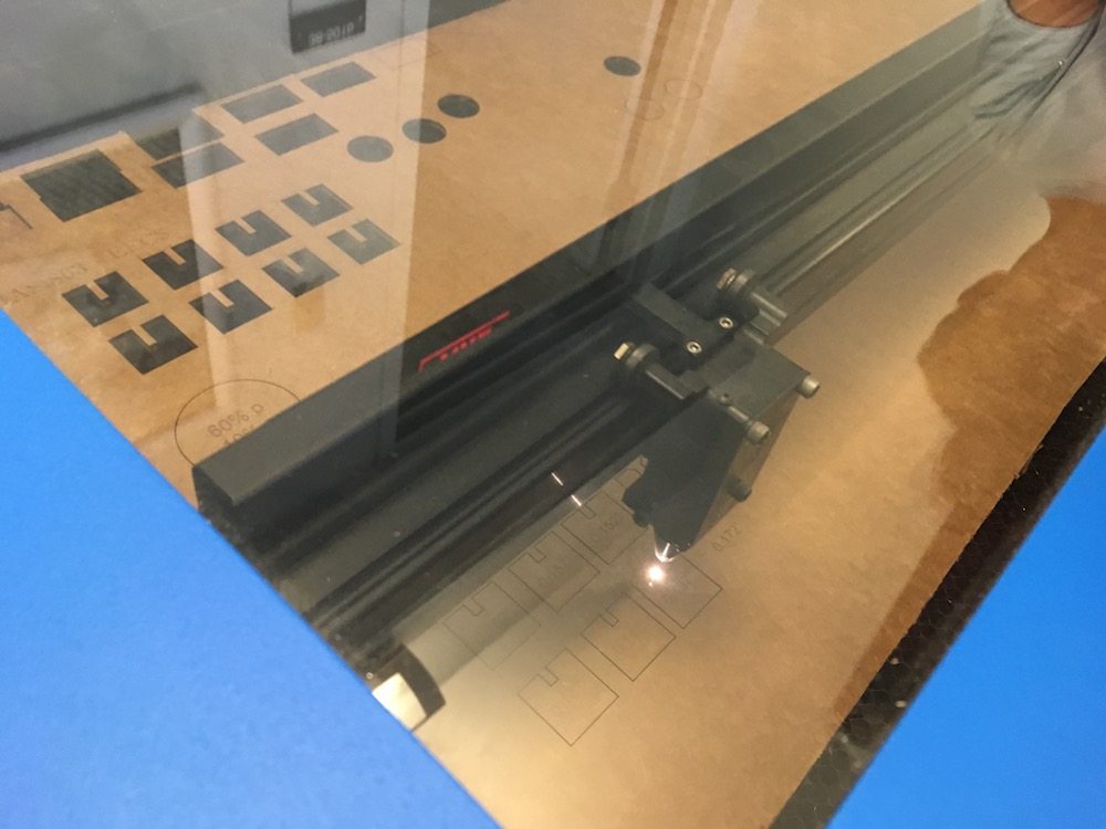
// snapshot of laser cutting hard at work! //
With those settings, our cuts came out excellent!
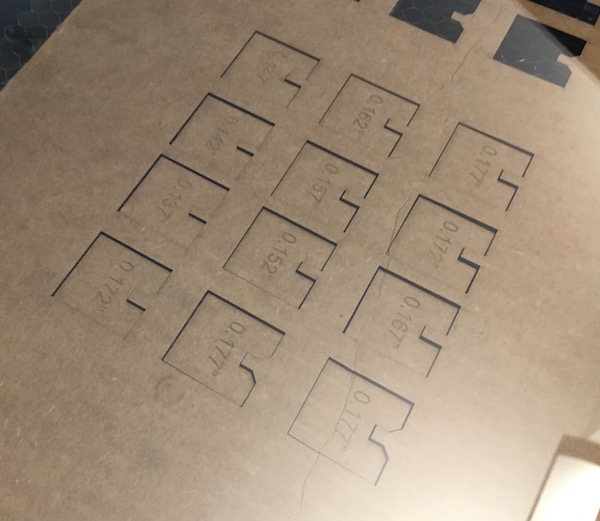
// laser cut slots with varying dimensions //
We played around with the various slot sizes and found that the smallest, 0.137", led to an ideal press-fit.
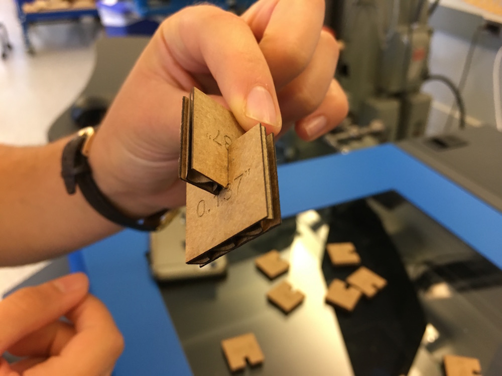
// successful press-fit with the 0.137" slot for a 0.177" thick cardboard //
01.02 // laser cut press-fit construction kit
For my press-fit laser cut construction kit, I decided to make a modular action figure, as a step towards designing my modular robot final project. First, I needed to determine all the pieces I would need to make. I quickly sketched out some ideas to keep me organized. I decided that it would be best if the action figure could be made from one type of piece, a simple cube.

// sketching idea of modular robot and press-fit cube components //
From there, I tried to make the cube out of as few pieces as possible. I was able to come up with a way to make a cube from just two distinct pieces. Below you can see the two distinct parts of the cube, and the cube assembled.
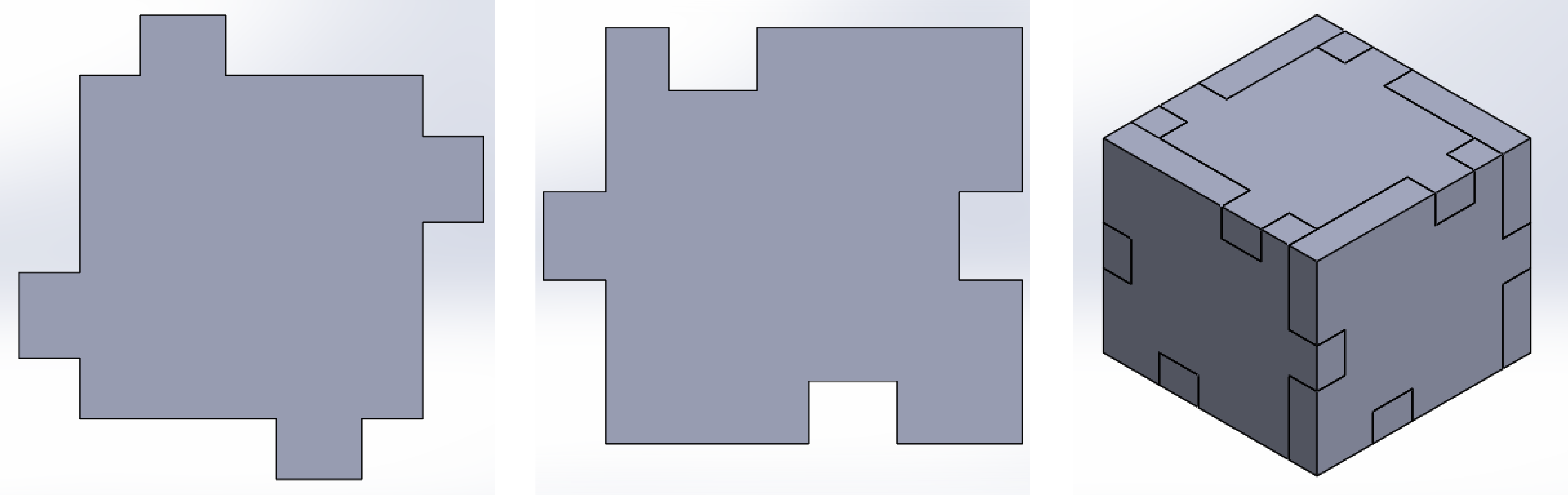
// solidworks models of two parts and resulting cube //
Using SolidWorks, a modeling software that I am already familair with, I was able to apply a lot of constraints between sketches in order to make modification of the tab or slot sizes very simple. This is crucial because I knew I would have to test out a few different dimensions depending on the laser kerf before I would get a good press-fit.
Shown here are a few of the different dimensions I tried before settling in a slot size of XX and a tab size of XX. With a successful cube made, the next step was to figure out a way that the cubes could be connected to one another. To do this, I decided to incorporate a flexure. Shown below, this double-sided flexure can be slipped into holes on one face of the cube in such a way that it is unlikely to pull out easily. Making things a bit more complicated, I knew that some pieces of the figure needed to rotate, like arms and legs. For that, I used the same double-sided flexure, but arc-shaped holes that allowed for the flexure to slide.
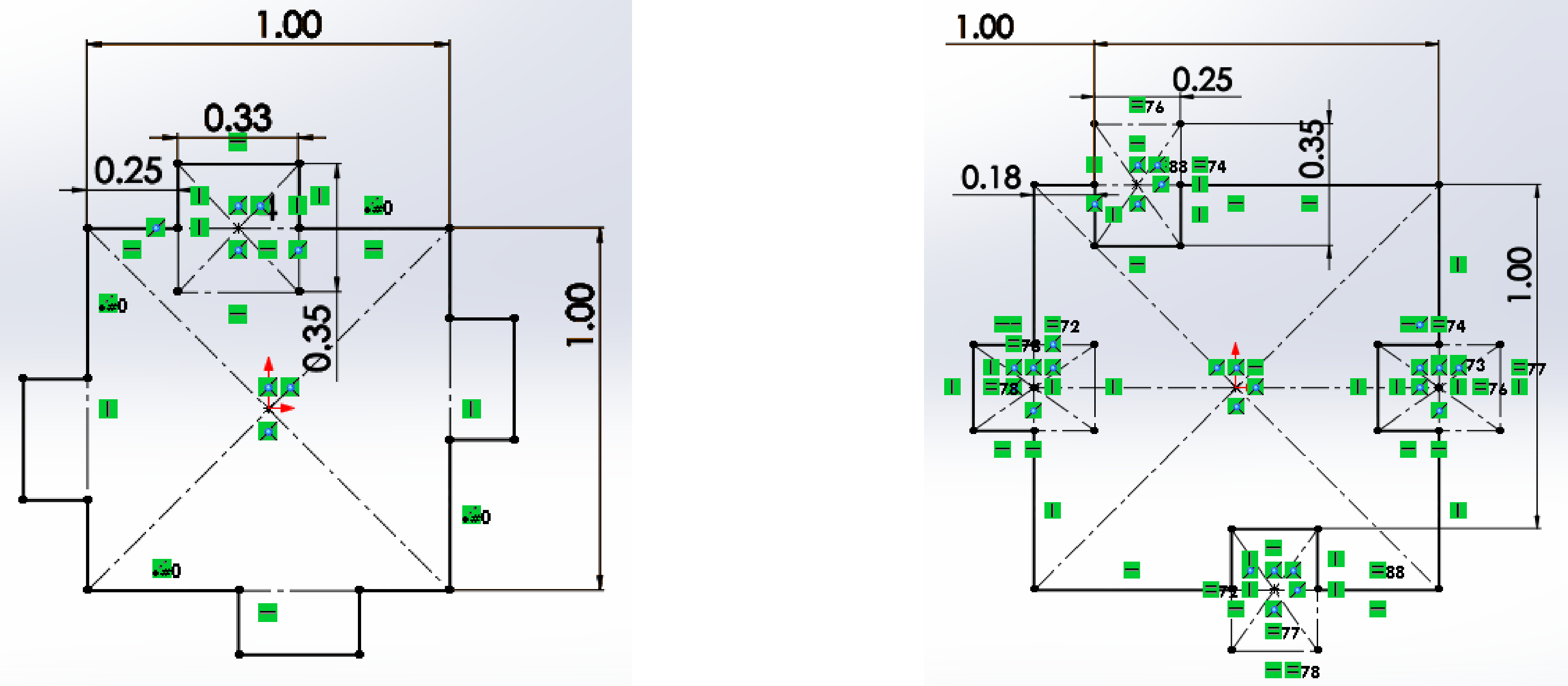
// sketch details of two parts //

// testing various slot dimensions //

01.03 // vinyl cutter