week 02 // electronics production
For this week's class, we had to use a table-top milling machine to mill out the traces of an in-system programer (ISP) from a blank, copper-covered, composite board made of FR1. From there, we had to solder surface-mount parts to fabricate the FabISP Board. This circuit functions as a programmer and once programmed, it can be used to load code onto other devices. Essentially, we "program the programmer." The idea behind our devices were that they could replace the more expensive, off-the-shelf programmers such as the AVRISP2.
02.01 // milling the board
In order to mill out the board, we used a Roland SRM-20 desktop mill, shown here. You can see that there is a layer of sacrifical layer of plastic and a large sacrificial sheet of FR1 board to which we can affix our pieces to.
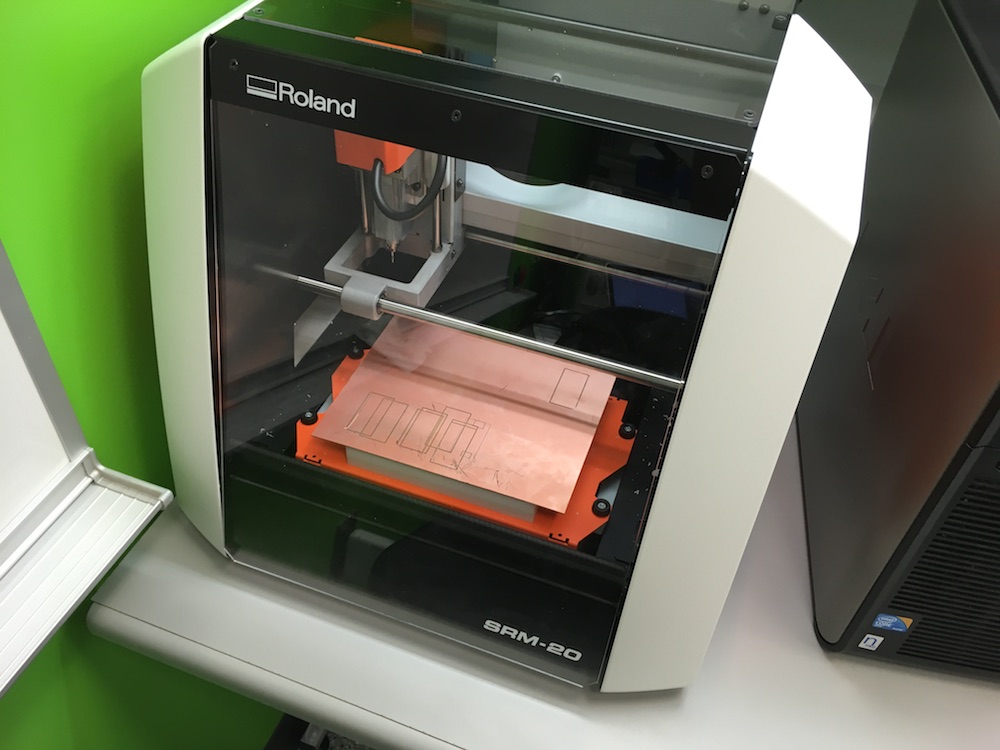
// roland srm-20 desktop mill //
The first step in milling the circuit out of the copper clad FR1 board was to ensure it was properly secured to the mill bed. To do this, I used a few pieces of double-sided tape and then firmly pressed the board down onto the sacrificial material on the mill bed.

// double-sided tape on back of FR1 piece to secure it to the mill bed // |
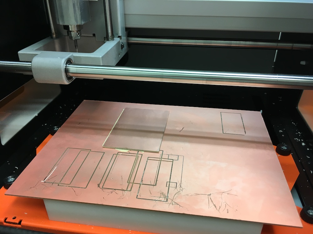
// FR1 piece secured to the mill bed // |
From there, the mill had to be programmed with the proper machine toolpaths. Using the SRM-20 PCB programmer, shown below, I first loaded the traces tool path and loaded the 1/64" inch endmill. See a screenshot of this program below.
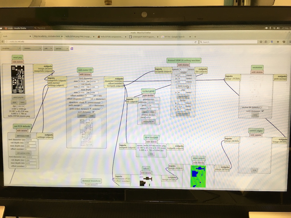
// screenshot of the SRM-20 PCB programmer //
// mill hard at work //
After the traces were milled, I vaccuumed up the copper chips and checked that the result of the job. As you can see here, the traces milled out perfectly! The piece did not shift during the cutting process so everything lineed up well.
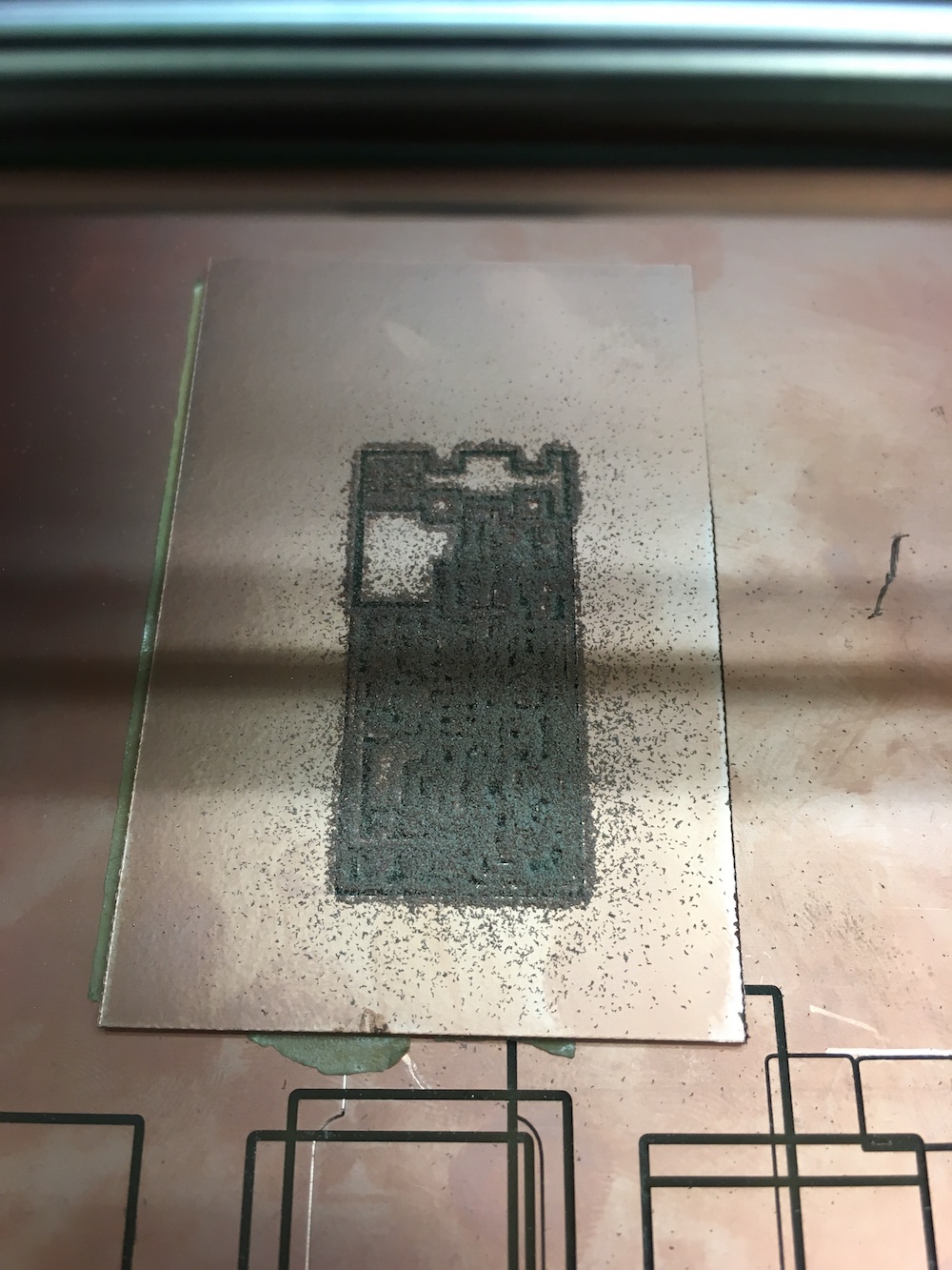
// what's left behind after the mill job // |
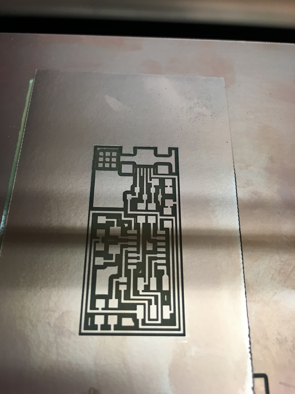
// freshly milled traces // |
02.02 // soldering the components
With the board milled successfully, the next step was to solder all the components to the board. We were given a layout to follow. In order to keep myself organized, I kept a neat sheet detailing all the components that I would be using, shown below.
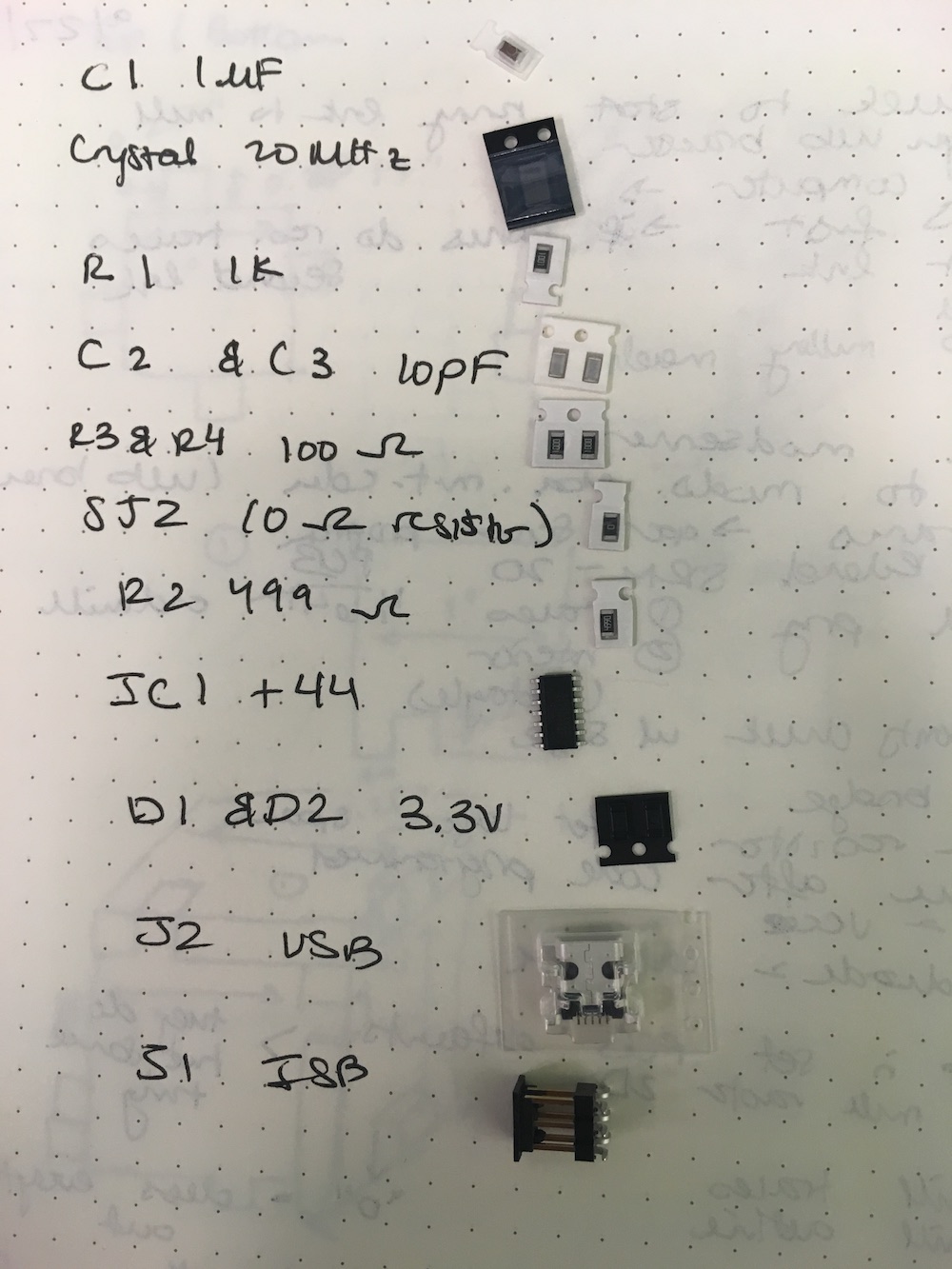
// just trying to keep it all organized //
I had previous soldering experience, but I had never done so for surface-mount components. I learned that a soldering iron with a very small tip, a pair of tiny tweezers, and small diameter solder, was the best way to accomplish this. It was a slow, but steady process!
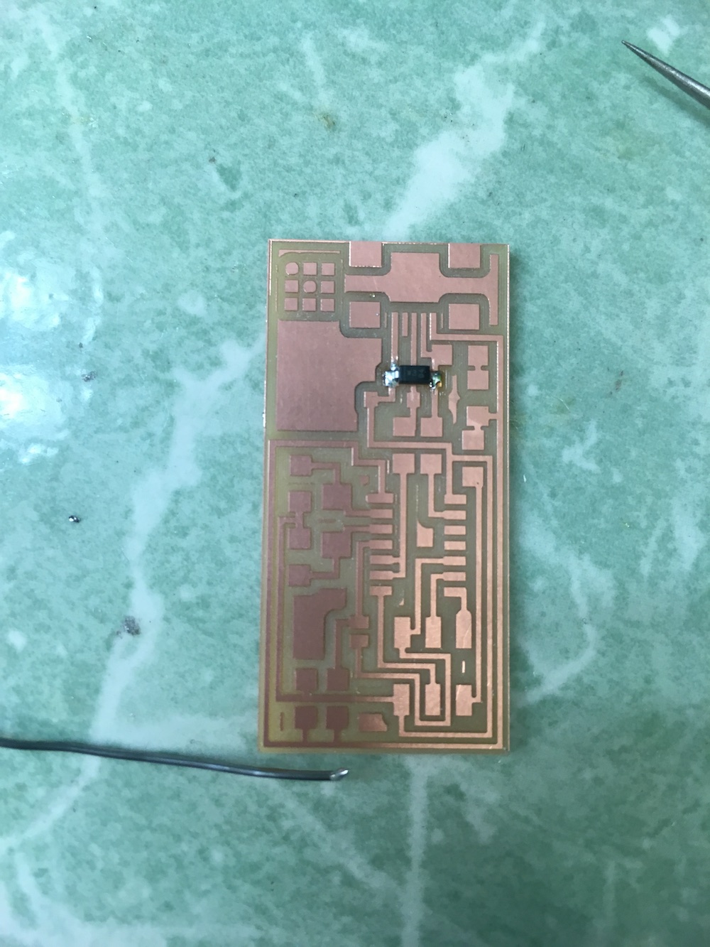
// one component down, so many more to go... //
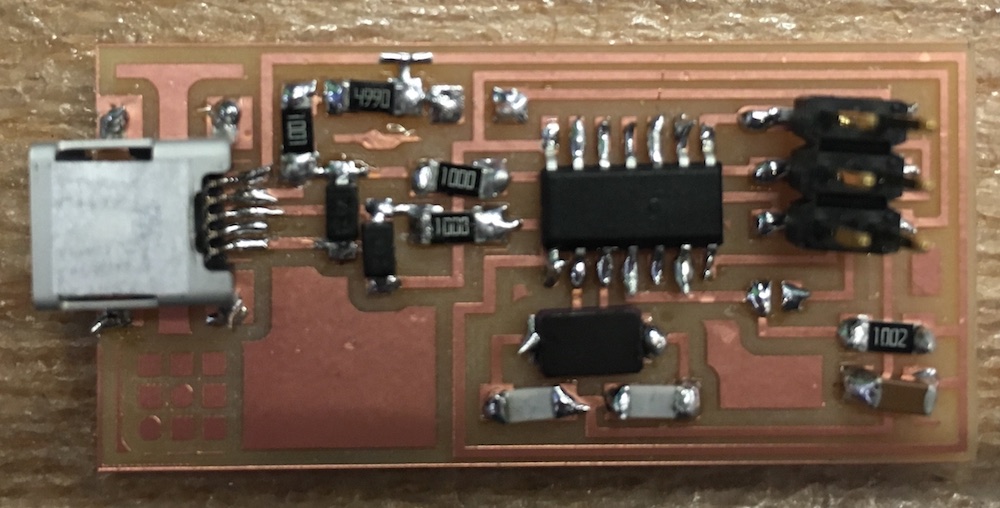
It was a long, tedius process, but with perserverance, I finished!
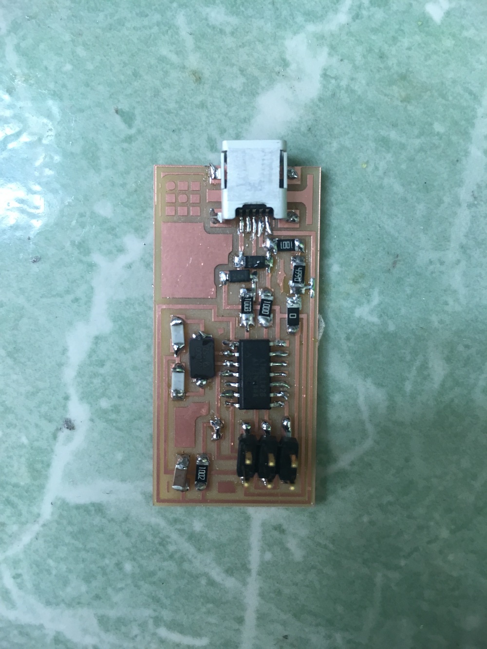
// final ISP board! soldered and ready to be programmed! //
02.03 // programming the board
In order to program the board, I plugged it into a USBtiny programmer using a 6-pin programming header. Then, both were plugged into my computer via USB and I followed the "make hex, make fuse, make program" approach in order to program the board.
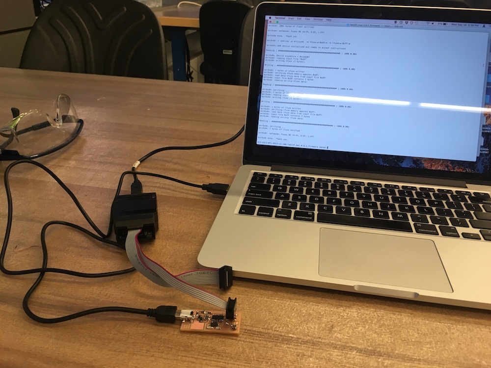
// ISP board plugged in to USBtiny //
Luckily, I did not run into any errors while programming. Phew! I then verified my board by going to the System Information menu on my computer and saw it was successfully programmed because it was recognized as FabISP! Woohoo!
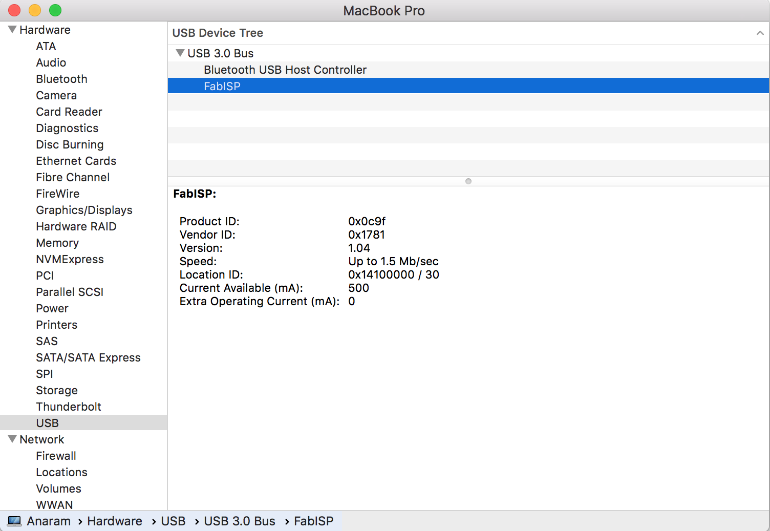
// success!!! //
Finally, in order to ensure that the board cannot be programmed again and instead used as a programmer itself, the zero ohm resistors had to be removed. And voila, my programmer is complete!
