week 03 // 3D printing and scanning
This week, we had to use a 3D printer to print something that could not be made subtractively. We also had to use the 3D scanner to scan an object and 3D print it as well. Before all of this, we had to work as a group in order to characterize our 3D printer and see how it's printing capabilities compares to those quoted by the manufacturer.
03.01 // characterizing the 3D printer
The 3D printer we are using in this class is the 3D Wox by Sindoh. According to the manufacturer's website, the specifications of the printer are:
| nozzle diameter | 0.4mm |
| max build size | 210 x 200 x 195mm (8”x8”x8“) |
| layer thickness | 0.05 ~ 0.4 mm |
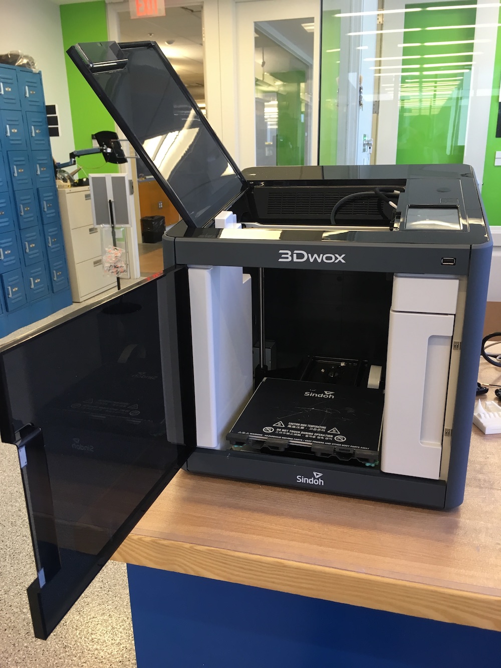
// 3DWox printer by Sindoh //
To examine the actual specs of the printer, we designed a series of rectangular prisms of varying side lengths and wall thicknesses. Below is a summary of all the cubes designed:
| cube | side length | wall thickness |
| A | 10mm | 1mm |
| B | 5mm | 1mm |
| C | 15mm | 1mm |
| D | 10mm | 2mm |
| E | 10mm | 0.5mm |
| F | 10mm | 0.4mm |
| G | 10mm | 0.3mm |
| H | 10mm | 0.2mm |
| I | 10mm | 0.1mm |
As you can see, some of the cubes have wall thicknesses smaller than the nozzle diameter. This suggests that they might not be printed, however we wanted to check that assumption. The idea was that once the cubes were printed, we could use calipers to verify the dimensions of the actual printed cubes.
In order to make the cubes themselves, we used SolidWorks. Using this program, we were able to generate a design table and automatically create 3D models for the various cubes.
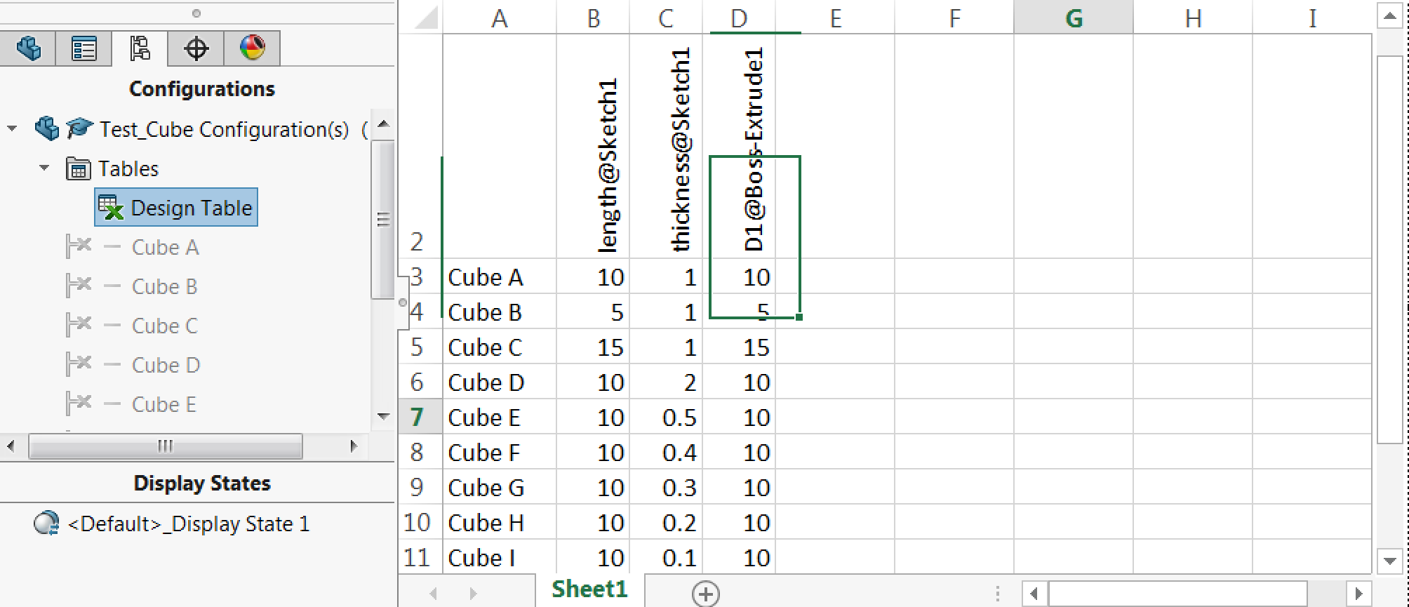
// using design tables in solidworks to generate multiple models //
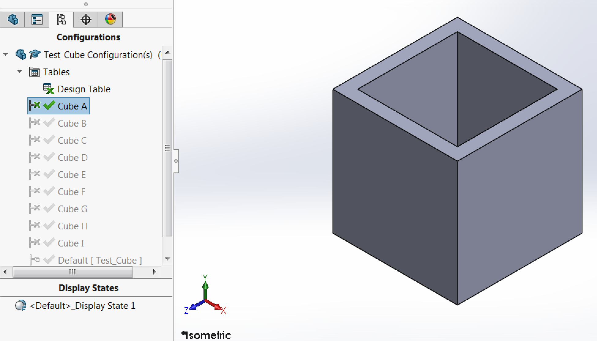
// cube a // |
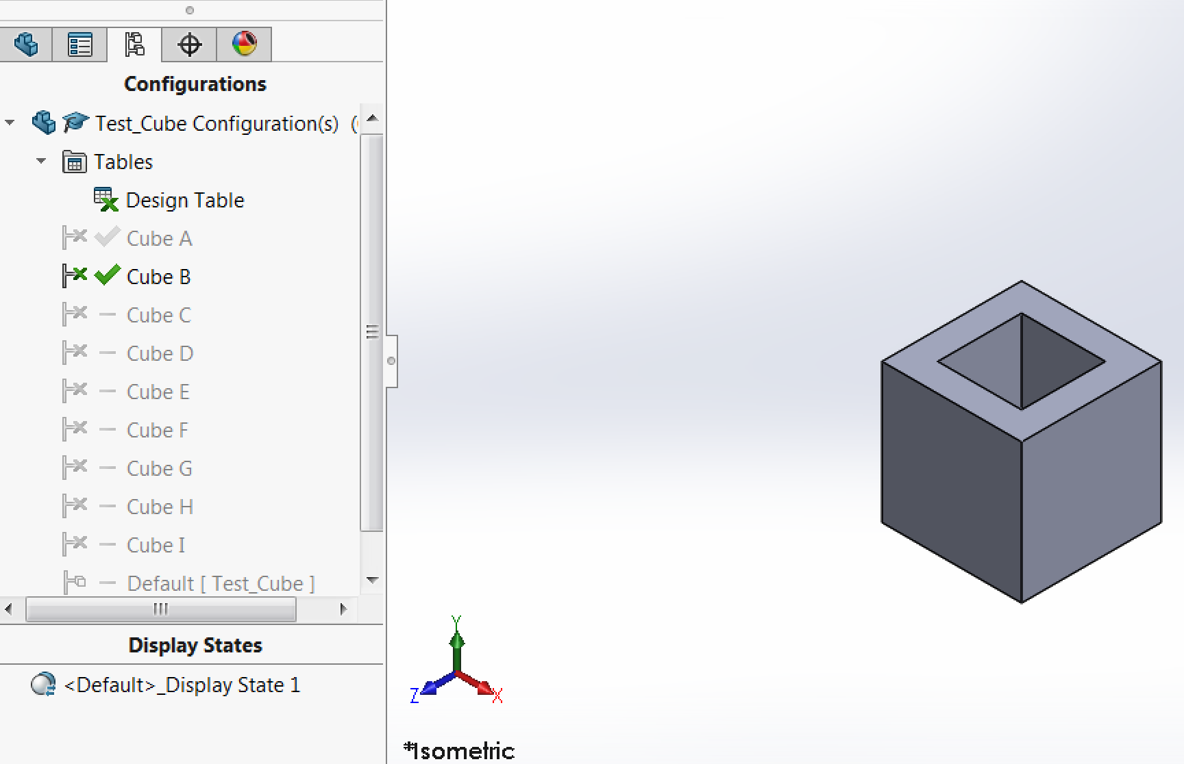
// cube b // |
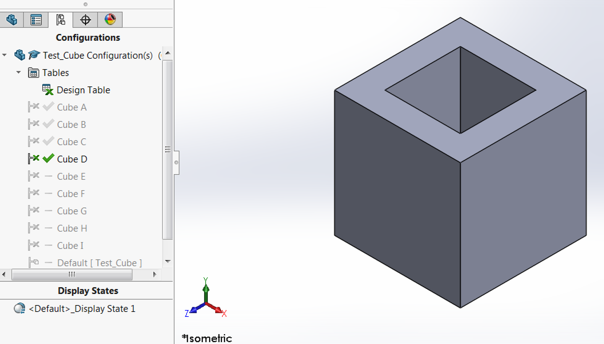
// cube c // |
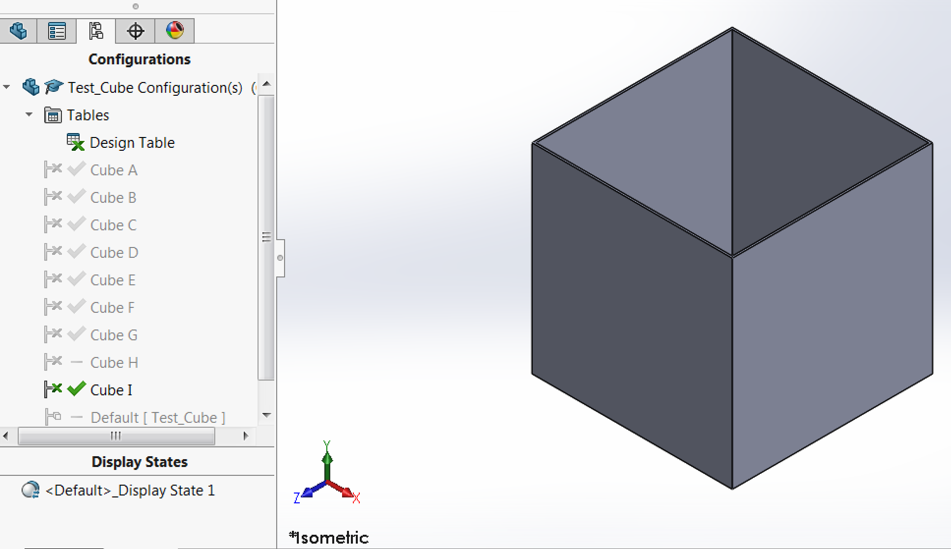
// cube i // |
// screenshots of a few of the cube models //
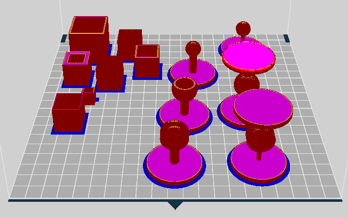
Once the models were made, we used the 3DWox printer to print them. First, we had to import each of the models into the 3DWox software. Then we have to orient and arrange them in a way that made the most sense printing-wise (eg. not using unnecessary support material). Finally, pressing "Print" would slice the model and generate a G-code file readable by the machine. Shown below are screenshots of the 3DWox software when importing the models for printing. In addition to the cubes, I began printing my individual assignment as well as the image created by the 3D scanner.
// model view in 3DWox software // |
// sliced view in 3DWox software // |
Fortunately, it seems the printer was pretty smart and realized that some of the cubes were unprintable due to their wall thickness. As you can see in the sliced view, a few of the cubes went missing, meaning they would not be printed. Additionally, the item I 3D scanned would require a lot of support material (it was "floating" in the area). Given these issues, I decided to remove the 3D scanned part from this print, and increase the cube sizes so that more of them would be printable. Using the 3DWox software tools, I scaled all the cubes up uniformly by two.
// sliced view in 3DWox software with scaled up cubes and no 3D scanner part //
With the models all loaded up and ready to be printed, I sent them to the printer and waited a little while for the initial raft layers to be printed to ensure the nozzle was clear and everything was going well. According to the software, my print was expected to take 7 hours and 34 minutes!
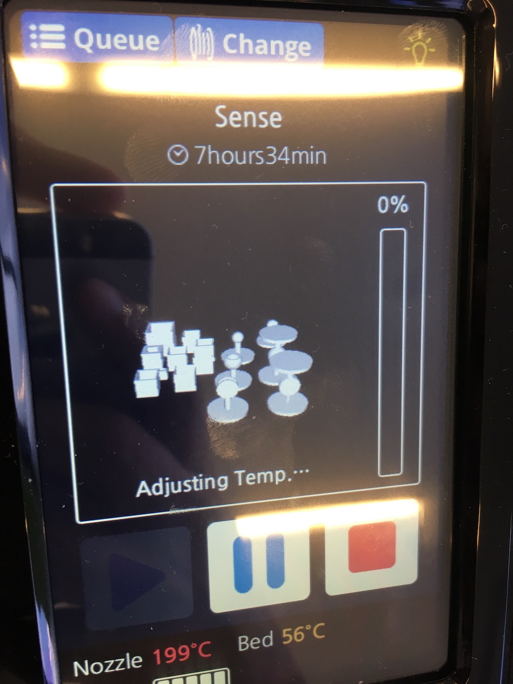
// time estimate and preview of 3d prints // |
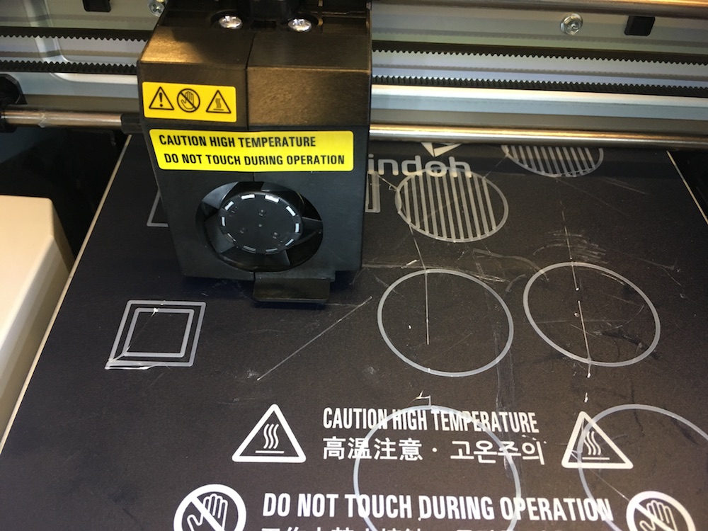
// initial raft layers being printed // |
After a looonnngg time, the prints were completed! Overall, they turned out pretty well. I was able to take calipers to the various cubes and verify their dimensions. The details are below (remember, they were scaled up by a factor of two in order to be printed). The side lengths were measured in all orientations using calipers and then averaged. All four wall thicknesses of each cube were also measured using calipers and then averaged.
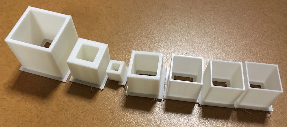
// final, printed test cubes //
| cube | side length | wall thickness | avg meas side length | avg meas wall thickness |
| A | 20mm | 2mm | 20.20mm | 2.04mm |
| B | 10mm | 2mm | 10.19mm | 2.04mm |
| C | 30mm | 2mm | 30.24mm | 2.05mm |
| D | 20mm | 4mm | 20.22mm | 4.02mm |
| E | 20mm | 1mm | 20.21mm | 1.04mm |
| F | 20mm | 0.8mm | 20.20mm | 0.85mm |
| G | 20mm | 0.6mm | 20.17mm | 0.71mm |
| H | 20mm | 0.4mm | did not print; | wall thickness <= nozzle diameter |
| I | 20mm | 0.2mm | did not print; | wall thickness <= nozzle diameter |
As you can see, in general, the 3DWox would not print anything that had features equal to or less than it's nozzle diameter. Additionally, there was an approximately 0.2mm expansion in the parts overall dimensions and on average about 0.05mm expansion wall thicknesses. Furthermore, this wall thickness deviation decreased the thicker the walls were and the larger the object that was printed. However, the z-dimension was often undersized by about 0.2mm for the smaller prints and as little as 0.03mm for the larger prints. I believe this discrepency probably has more to do with the number of layers and layer thickness as the printer has a large range from 0.05mm to 0.4mm.
03.02 // 3D printing part
For the individual portion of this week's assignment, we had to design and print an object that could not be made subtractively. Thinking about my final project, I decided to try printing some possible joints for a modular robot. I decided these would be best 3D printed because I could print both a male and female portion of a joint, already assembled, with support material to fill in the gaps.
In addition to the 3DWox, we had access to a uPrint which uses dissolvable support material. This would be perfect for things like the socket joints I had in mind. After some brainstorming, I decided it would be best to try and design some joints for arms and legs of the robot. For arms, I knew they required a large range of motion in multiple directions, so I decided that a socket joint would be best. With regard to the legs, I decided I could get by with just one range of motion and therefore decided on a circular slider type joint.
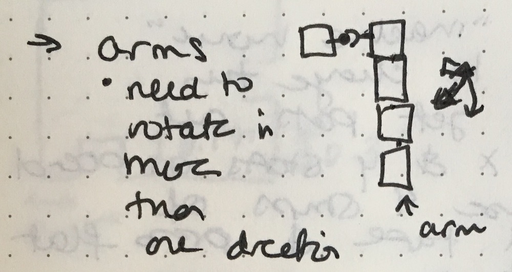
// arm joint requirements // |
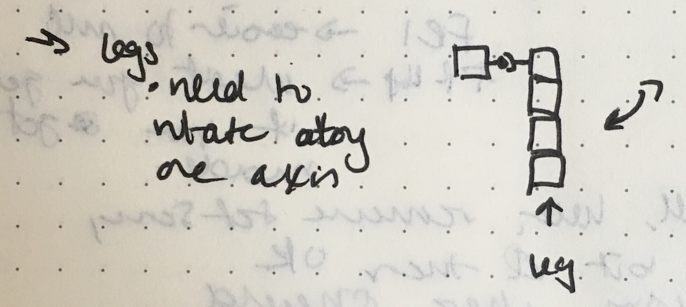
// leg joint requirements // |
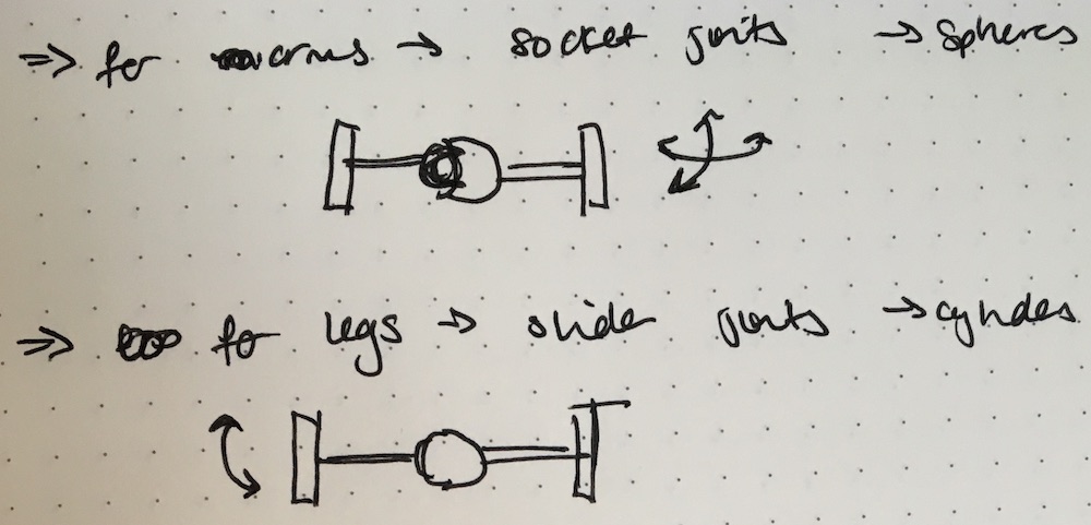
// types of joints //
Once my ideas were complete, I went to SolidWorks to model up the various pieces. Each joint would require a male and a female part, and I wanted to try printing them as an assembly with dissolvable support material filling in the gaps.
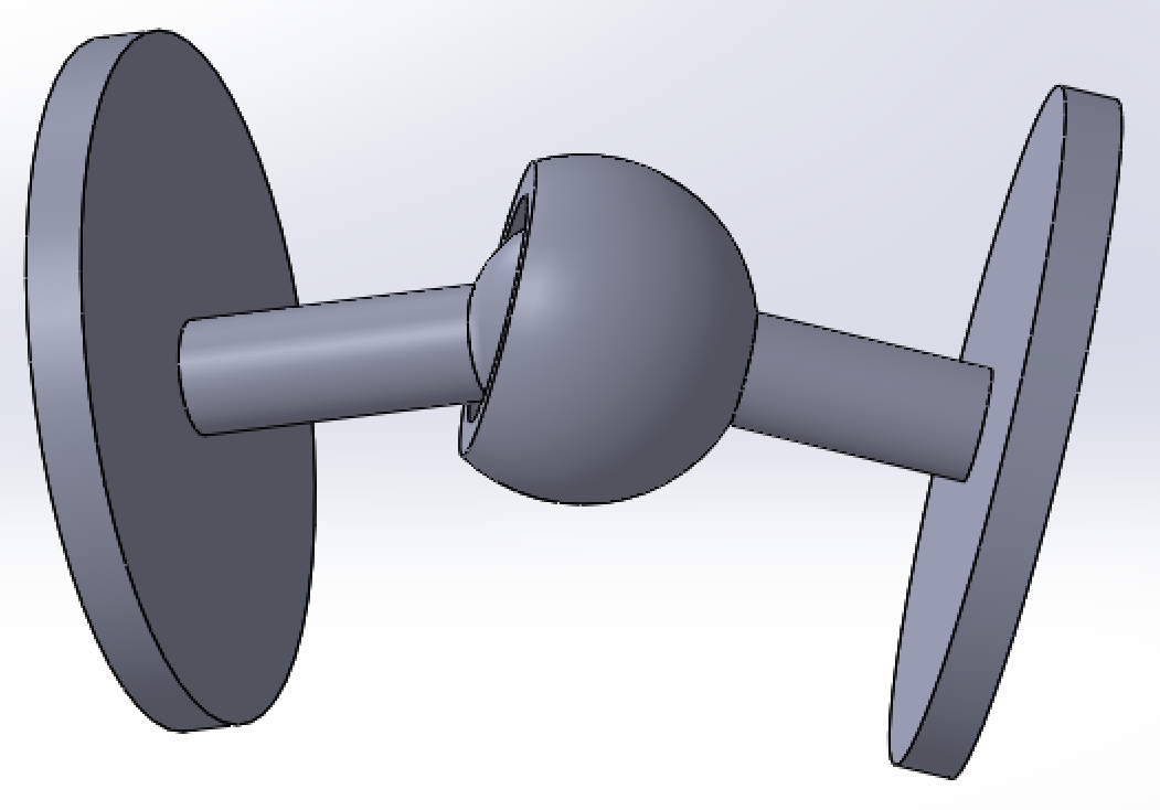
// socket joint assembly // |
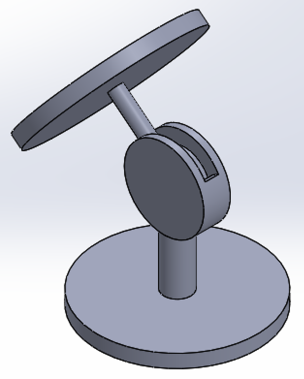
// cylindrical slider joint assembly // |
I decided to also print these items on the 3DWox, just to see how the individual parts would turn out as well as the assemblies. I was curious to see if I could press-fit together the male and female parts if they were printed on the 3DWox, or if I could remove the support material from the assemblies printed on the 3DWox, or if they truly required dissolvable support material to work. In the case of the 3DWox, the parts were printed with the cubes used to characterize the printer (described above).
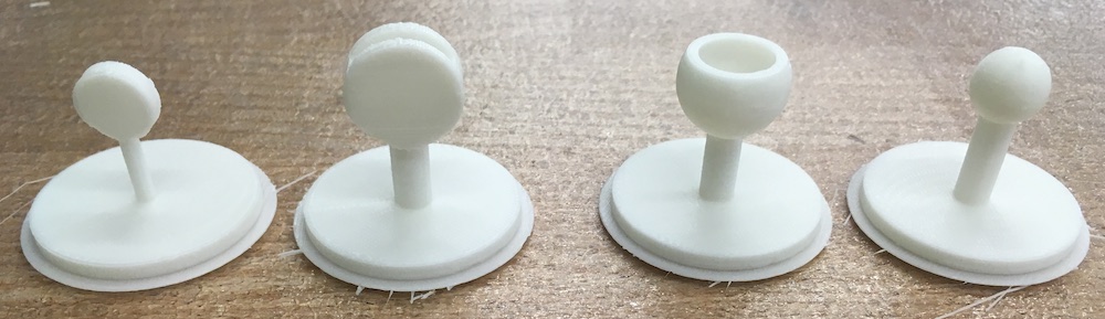
// final separate joints as printed on the 3DWox //
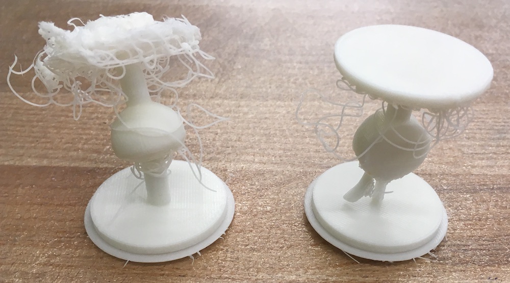
// final combined joints as printed on the 3DWox //
As you can see, while the separate joints printed great, the combined joints did do so well. It seems that there was probably an issue with the lack of support material surrounding the combined joints which caused the part to shift often and hence not print well. However, the combined socket joint actually moved! Additionally, the dimensions on the male and female socket joints were such that I was able to press-fit them together and they worked as well!
// even though the printer failed for the combined socket joint, it works! //
// the separate socket joints fit well together and work! //
Using the uPrint was slightly different than the 3DWox. It involved printing the parts and then submerging them in a bath in order to dissolve away the support material.
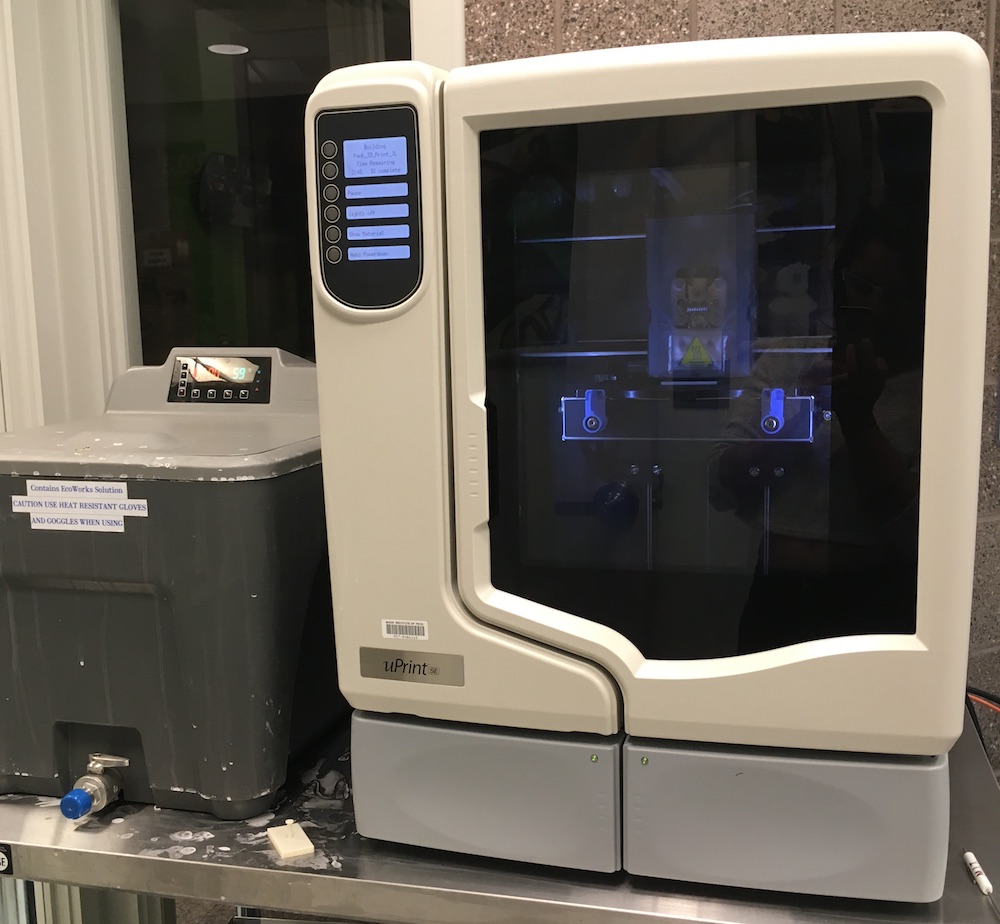
// uPrint SE (right) and bath (left) //
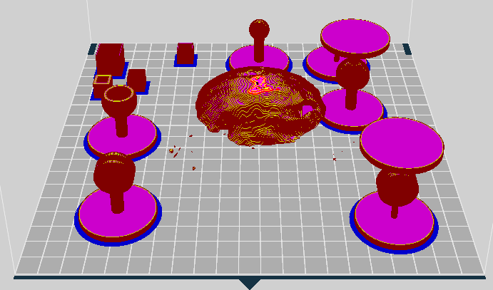
The uPrint software was fairly straightforward. I was able to import the STLs of the SolidWorks assemblies of both types of joints. From there, I was curious as to printing in a different orientation might affect the part so for each of the parts, I tried orienting them in two ways. From there, I laid out all the parts on the bed in the software and sent the print to the uPrint.
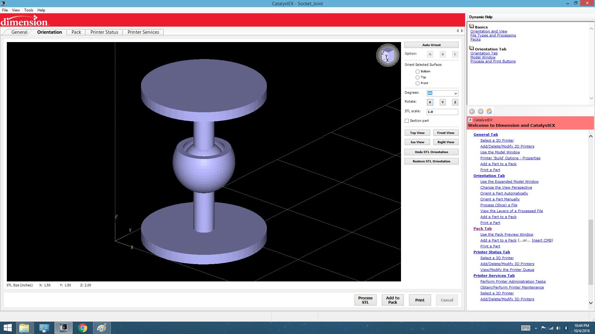
// screenshot of uPrint software //
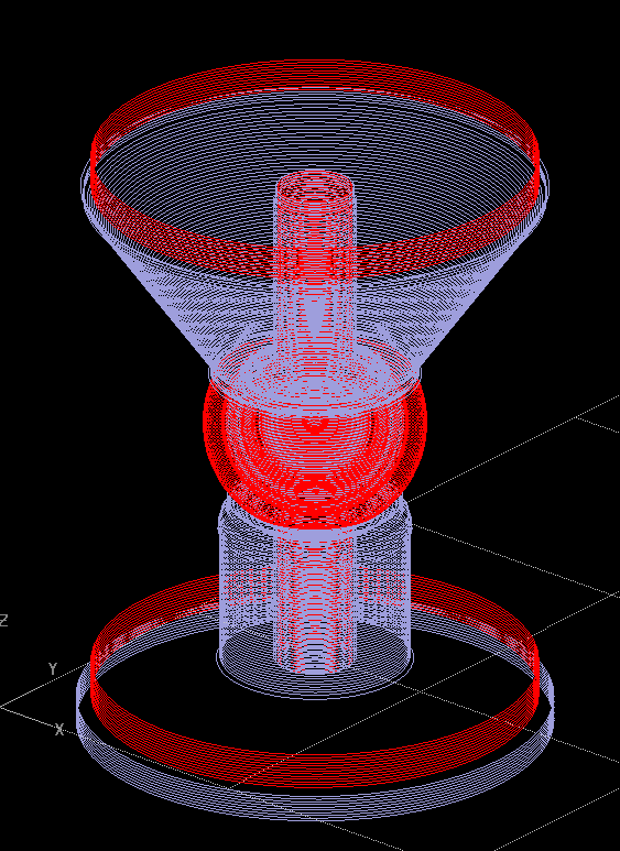
// processed orientation of socket joint showing print layers. build material (red) and support material (blue). // |
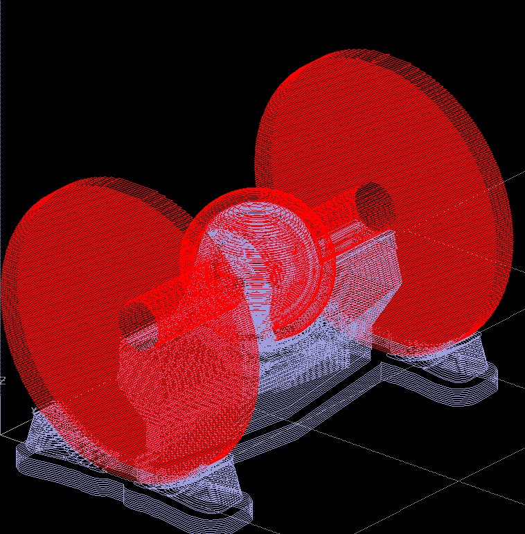
// processed alternate orientation of socket joint showing print layers. build material (red) and support material (blue). // |
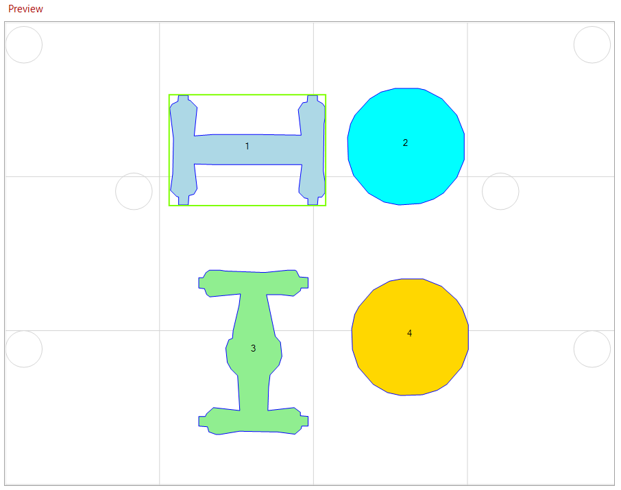
// screenshot of parts layed out on bed. //
All in all, the print took 5:36 hours, and the bath required XXX minutes.

// final joints as printed on the uPrint //
03.03 // 3D scanning
For this week's class, we also got a chance to try 3D scanning items! We used the 3D Sense scanner. Through trial and error, I found that the best way to use the scanner was to actually have it mounted on a tripod with the object to be scanned on some sort of rotating platform (like a stool!) in front. It was much easier to swivel the platform than it was to try to keep the camera steady moving around the object.
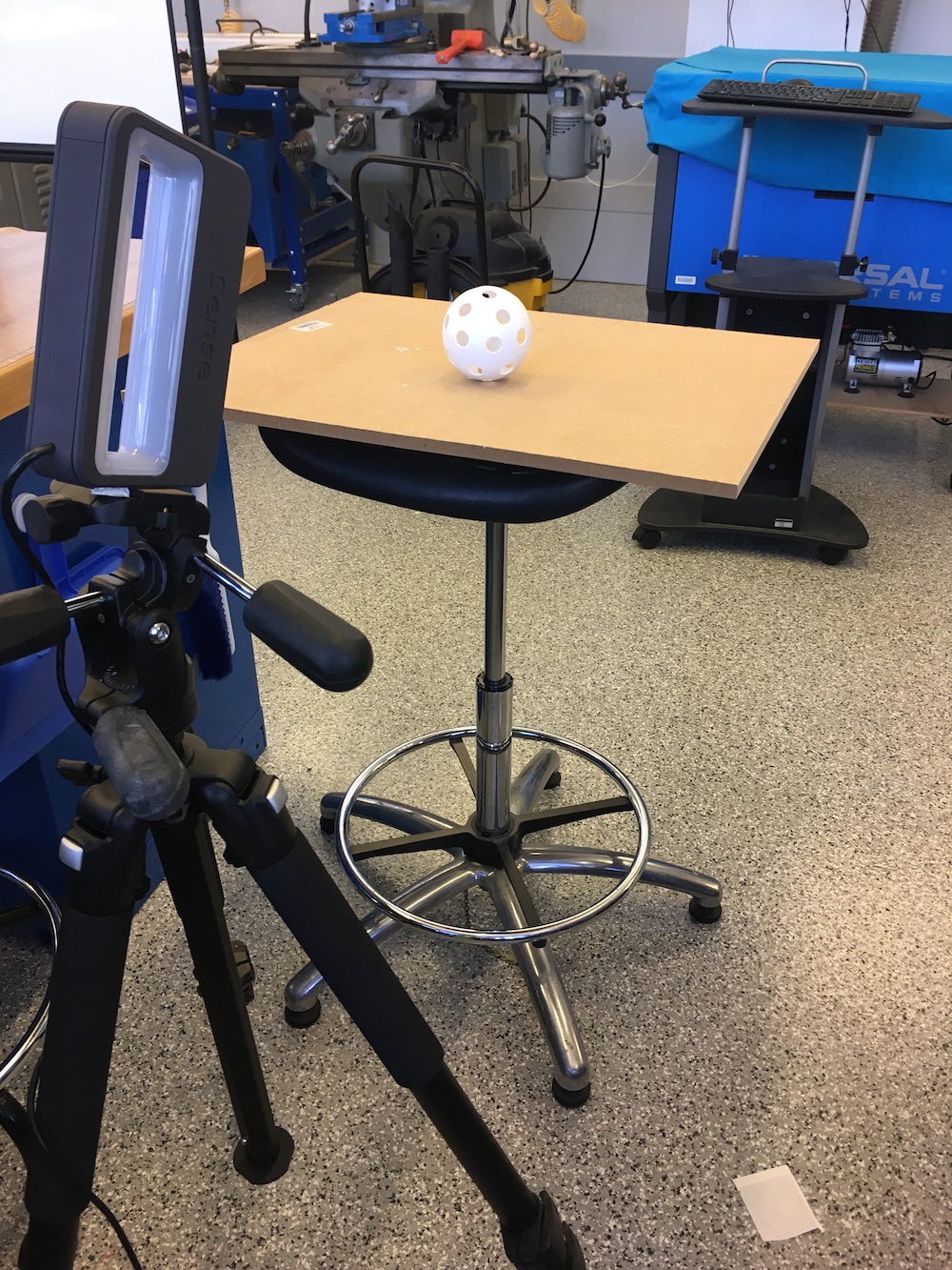
// 3D Sense scanner set-up //
From there, the software was fairly straight forward and guided you through selecting the size of object you were scanning and when to rotate the object or camera to scan all sides of it.
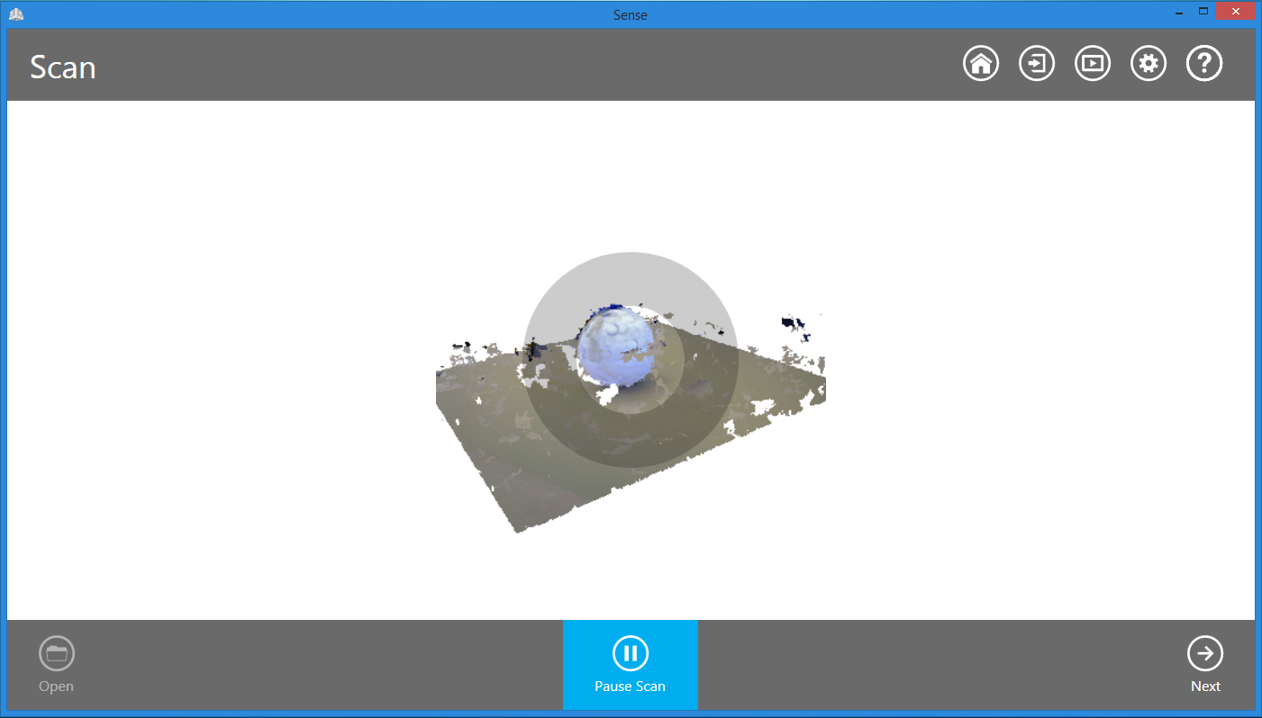
// screenshot of 3D Sense software //
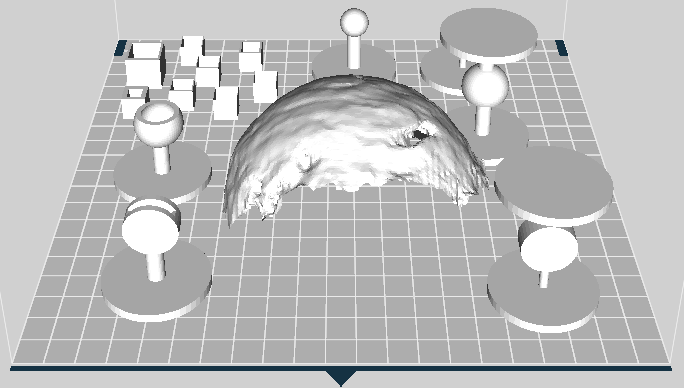
I decided to try scanning a large wiffle ball because I was curious about how the scanner would pick up holes. Unfortunately, it wasn't able to do pick up the entire ball, nor did it identify the holes (they did show up as indents though, so that might be a start!).
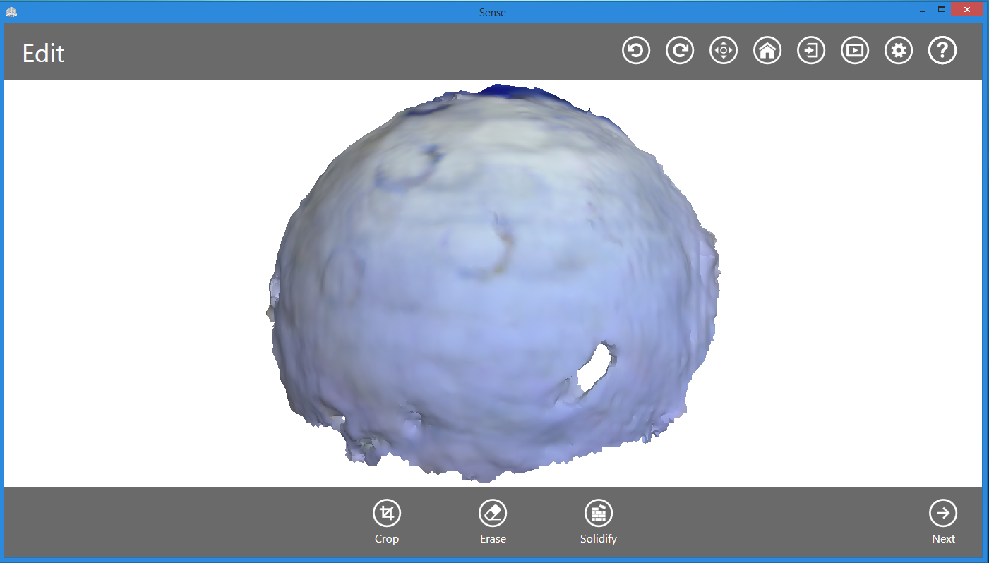
// 3D scan of wiffle ball //
I also tried exporting the model as an STL file for printing, however because the 3D scanner did not determine the object to be a sphere, but rather a hollow top shell of a hemisphere, the resulting print would require a lot of support material to print.