week 07 // molding and casting
This week's assignment was to design a 3D mold, machine it, and cast parts from it. This involved the following steps:
- Design a positive 3D mold
- Machining the positive mold
- Use it to cast a negative 3D mold
- Cast a part from the negative 3D mold
07.01 // design a positive mold
Given that summer is most definitely gone from Boston and winter is inevitably coming, I decided to design a mold to cast a snowman. To do this, I first found a 3D model of a snowman from GrabCad. After looking through a number of the posts from previous students of this class for the molding and casting week, I decided that it was best to try to cast a part that was as simple as possible, with the least amount of small pieces or details.
With the 3D model in hand, I used SolidWorks to make the two halves of the positive 3D mold. I made sure to include some mating features so that the two negative mold halves that would be casted, could be easily lined up. I also placed the snowman's hat right at the top of the mold so it could double as a spout for the plaster that would be used in the final casting step.
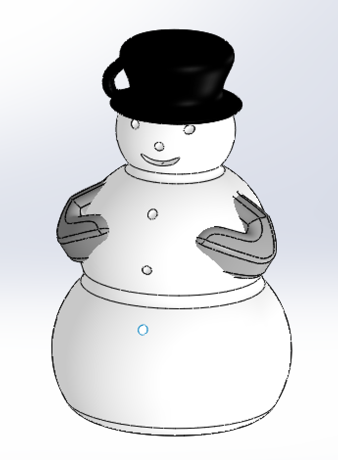
// 3d model of snowman // |
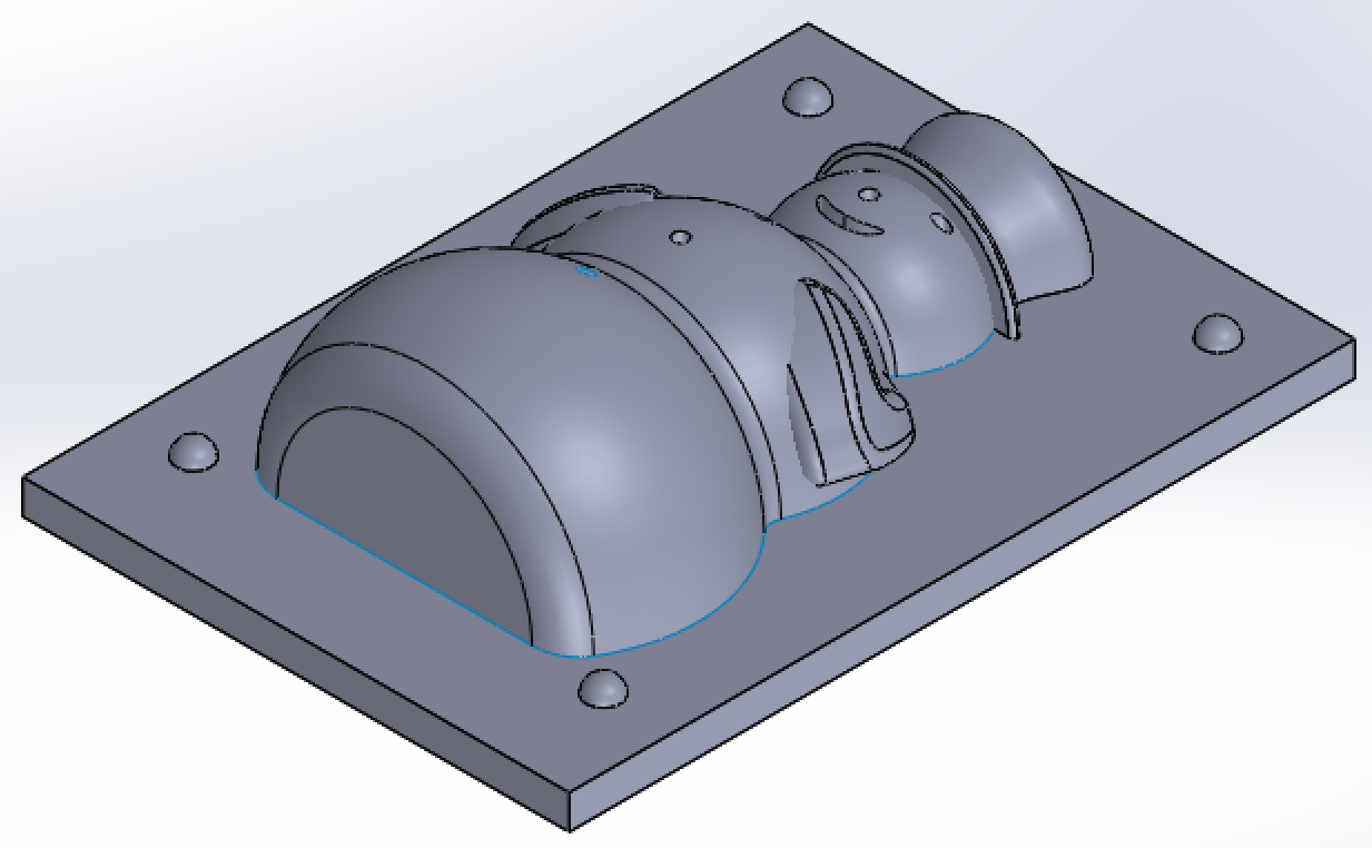
// positive mold of front half of snowman // |
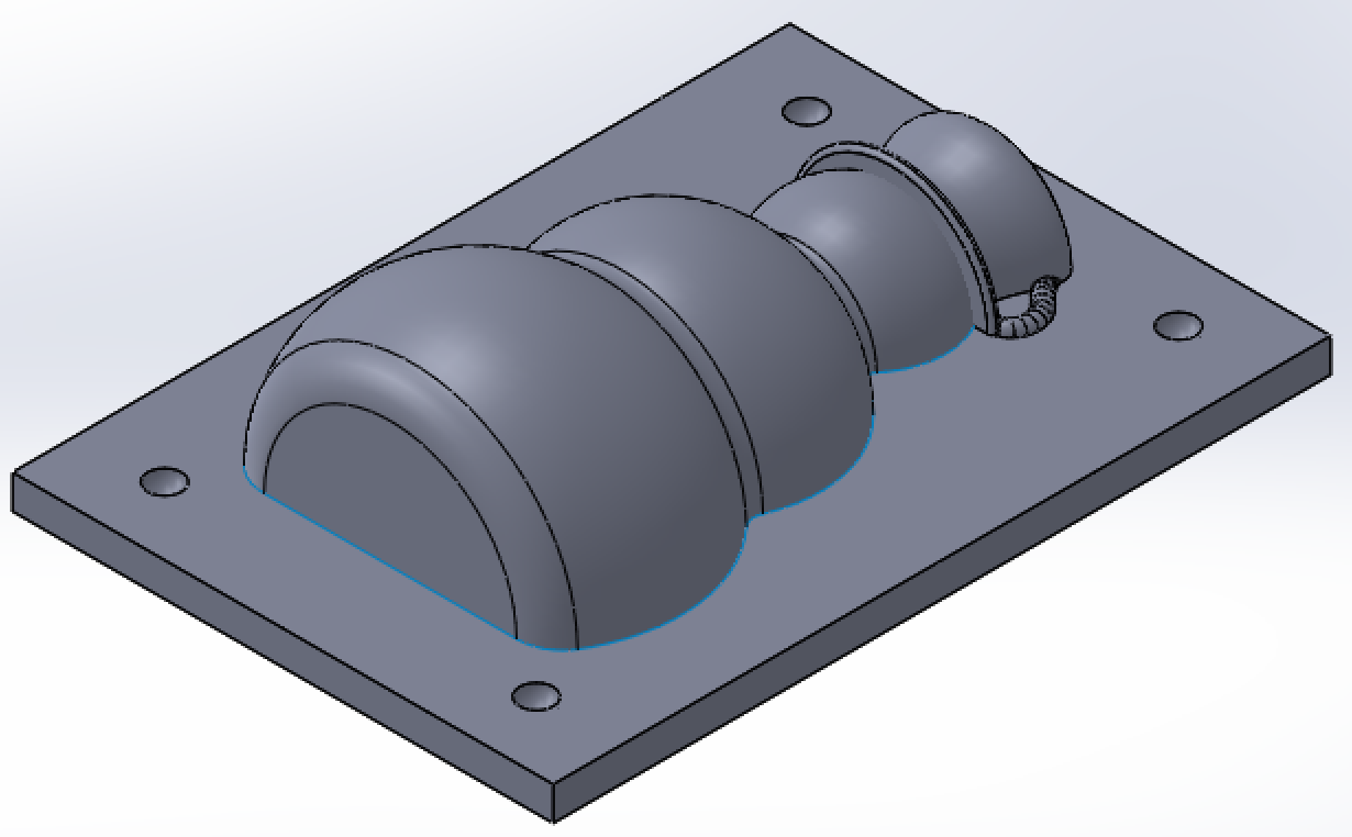
// positive mold of back half of snowman // |
Finally, I scaled the model to ensure that both parts could be machined out of the wax block we were given in class, whose dimensions were 3.5" x 3" x 1.5" and saved each of the halves as .STL files for use with the fabmodules script. I also used meshlab to view my files and ensure there were no issues with the meshes.
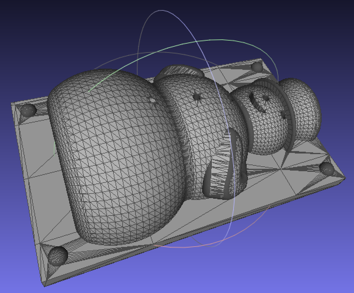
// mesh of front mold // |
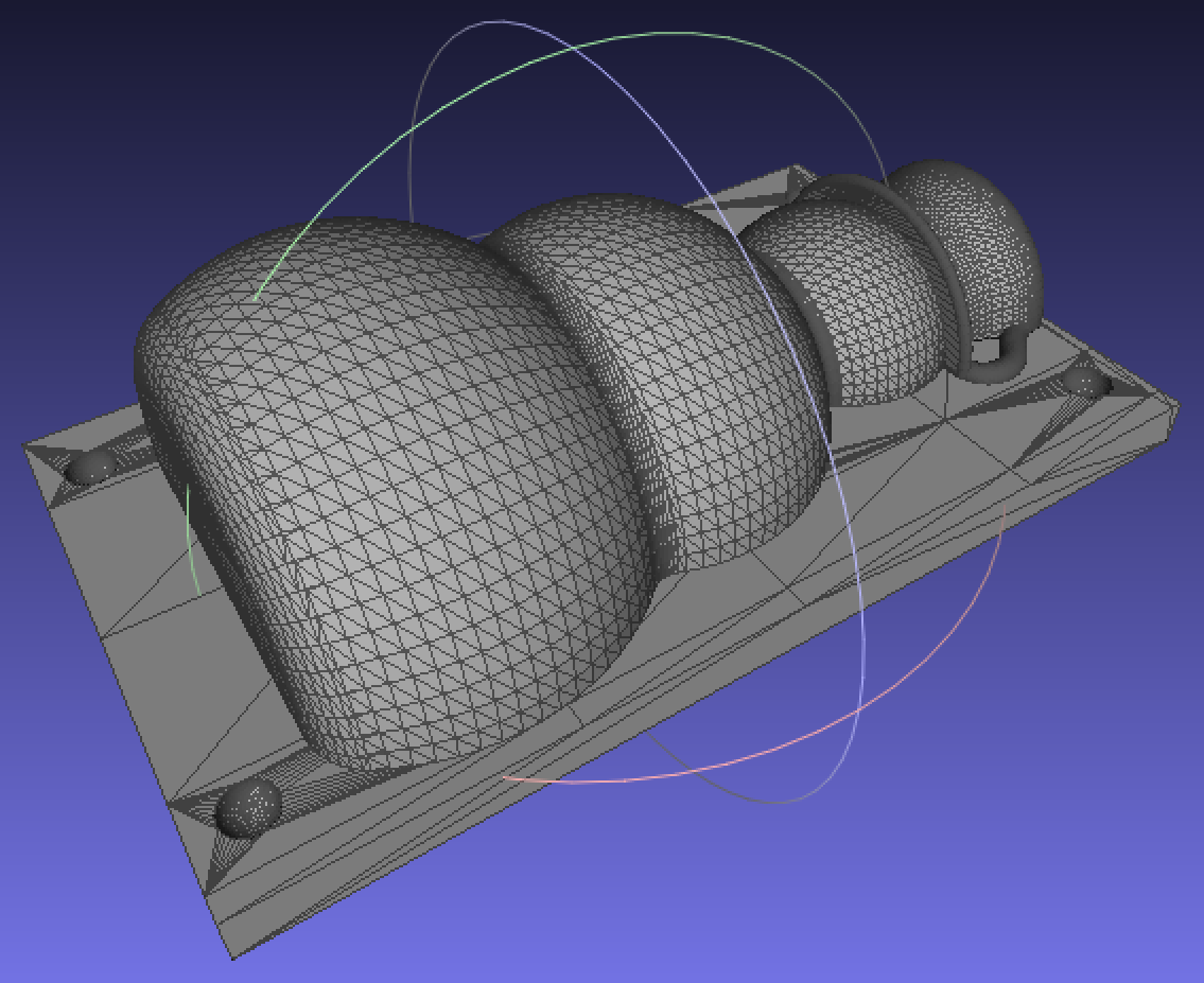
// mesh of back mold // |
07.03 // machining the positive mold
To machine the two positive molds, I used an Othermill, a desktop CNC for electronics and small parts. I used the fabmodules script to convert the .STL files into toolpaths in .nc files (g-code) readable by the Othermill. The process took a LONG time because there were no settings for machinable wax. Instead, I had to do a LOT of trial and error to determine the best setting for both the rough and fine cuts I wanted to do.
// trial and error testing settings for othermill toolpaths //
Some key points I learned:
- All mesh files should be saved with ".stl" as the extension, all lowercase, not ".STL."
- Once the mesh is inputted, change "units/in" to "25.4" if the model is in inches.
- Ensure that the model is rotated so that you are viewing from the top down.
- Reduce the dpi to "300." The default is "1000," which results in unnecessarily long calculation times.
- Press "calculate height map." If your mesh is oriented correctly, a height map of varying colors will show up where the mesh image was.
- Select "Othermill (.nc)" as the output file type.
- Under "output," change the spindle speed to "6000."
- For "process," select "foam rough cut (1/8)" for a rough cut of your model and "foam finish cut (1/8)" for a finer, finishing cut of your model (this process assumes a rough cut has already been done.)
- Under "process," change "bottom z" to be negative and at least the depth of your model (shown in the "input" section), but no more than the depth of your material. Since we are machining molds, this value should be slightly larger than your model depth to ensure there is some material poured over the top of your mold during the casting process.
- Change the "cut depth" to "1." I found that a cut depth the same size as the bit diameter caused a lot of issues and often resulted in the material coming loose from the bed of the machine. I reduced this to 1 mm and had no issues. I suspect it could be increased a bit more, but I didn't spend too much time playing around once I found that 1 mm worked well. Note that if you are creating a finishing tool path and selected "foam finish cut (1/8)", there will be no option for the cut depth.
- Press "calculate" to calculate the toolpaths. Once that is done, press "save" to save your .nc file.
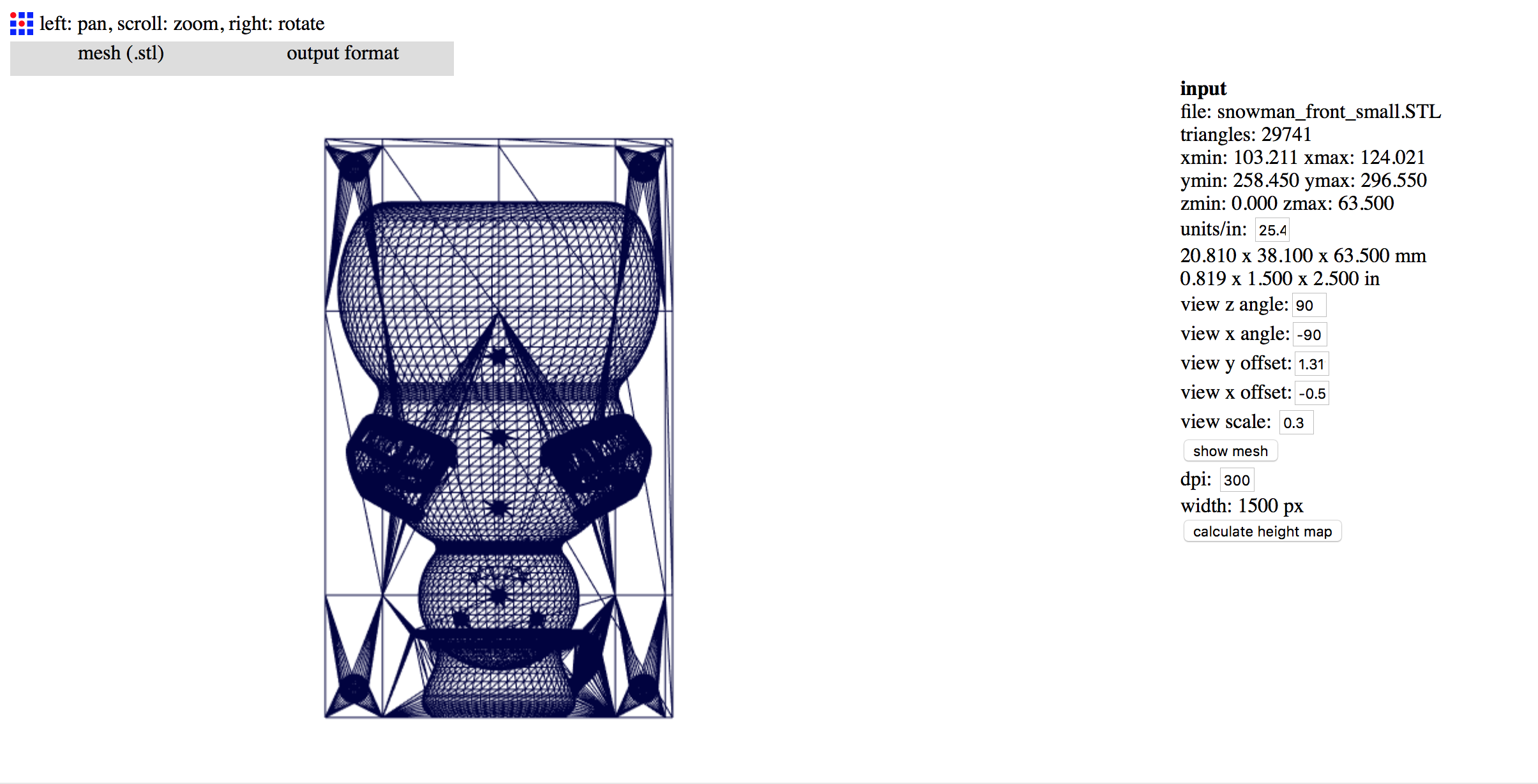
// importing the mesh into fabmodule //
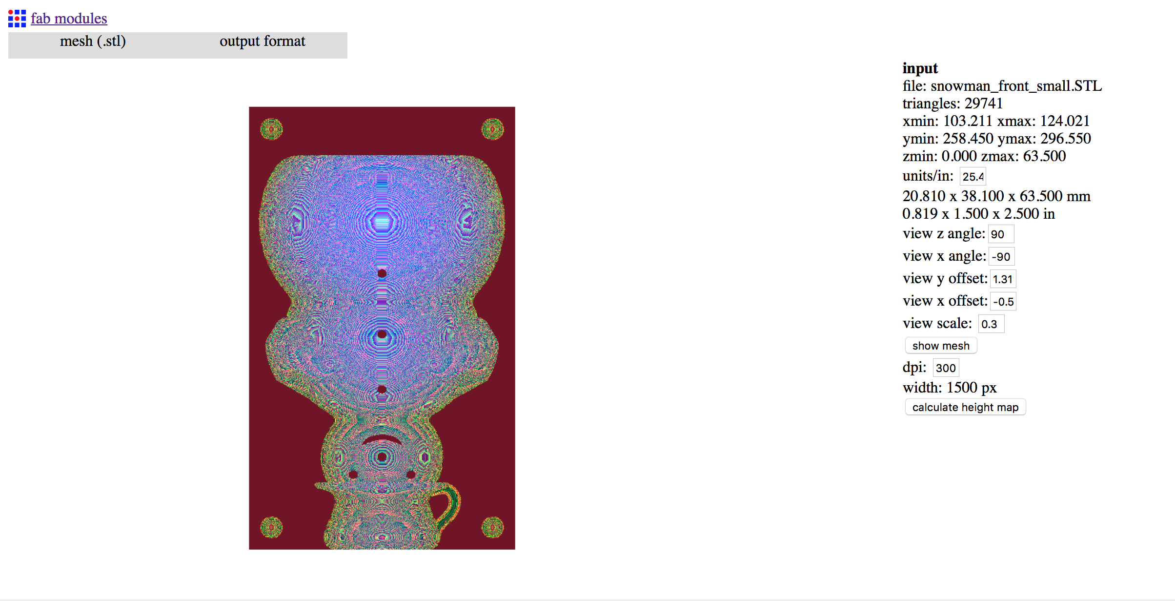
// calculating the height map //
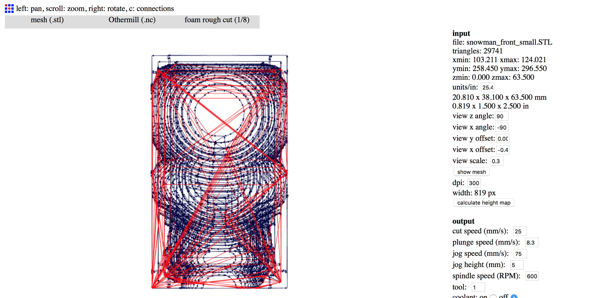
// rough cut tool path //
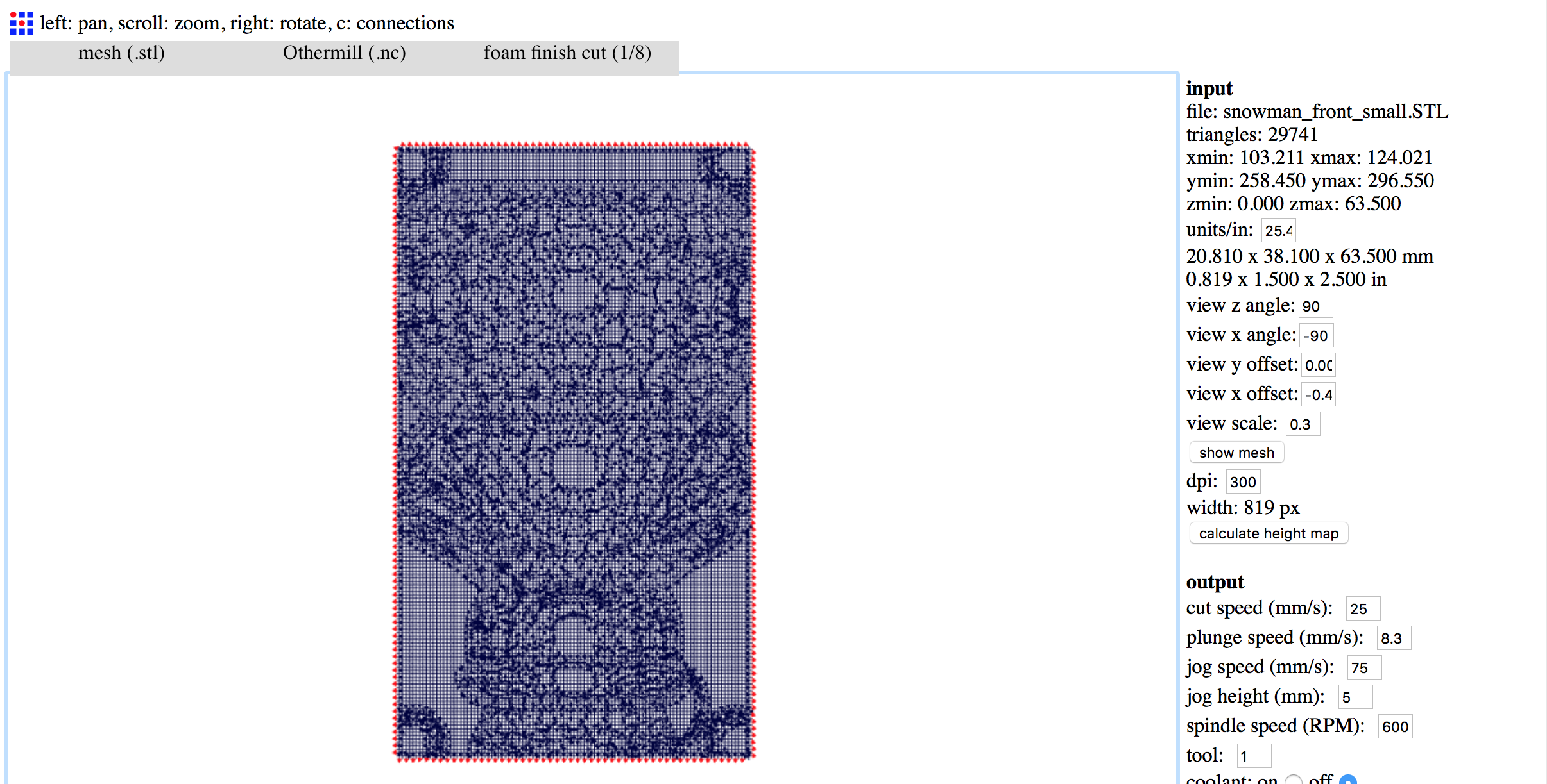
// finish cut tool path //
Once the .nc file has been generated, it can be loaded into Otherplan, the Othermill software for setting up and running a CNC job on the machine. For this part, I followed the instructions found on the Othermachine website. Fixturing was done simply by using double-sided tape, as suggested by the support website.
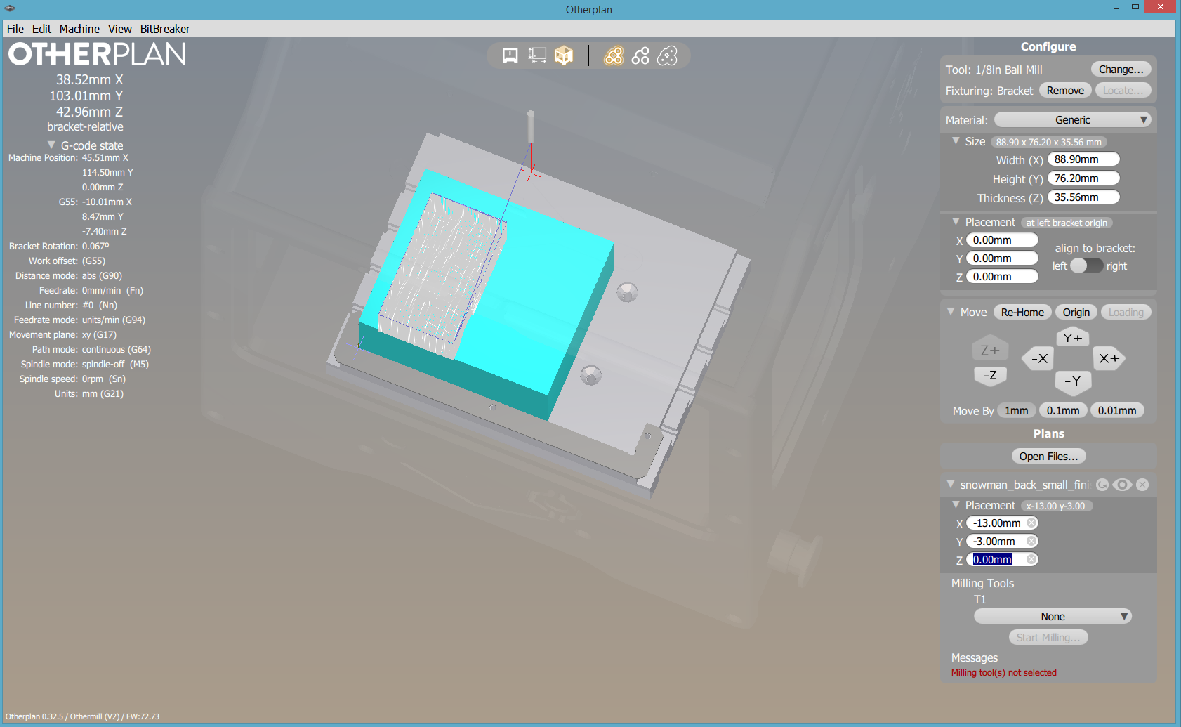
// finish cut tool path loaded into otherplan //
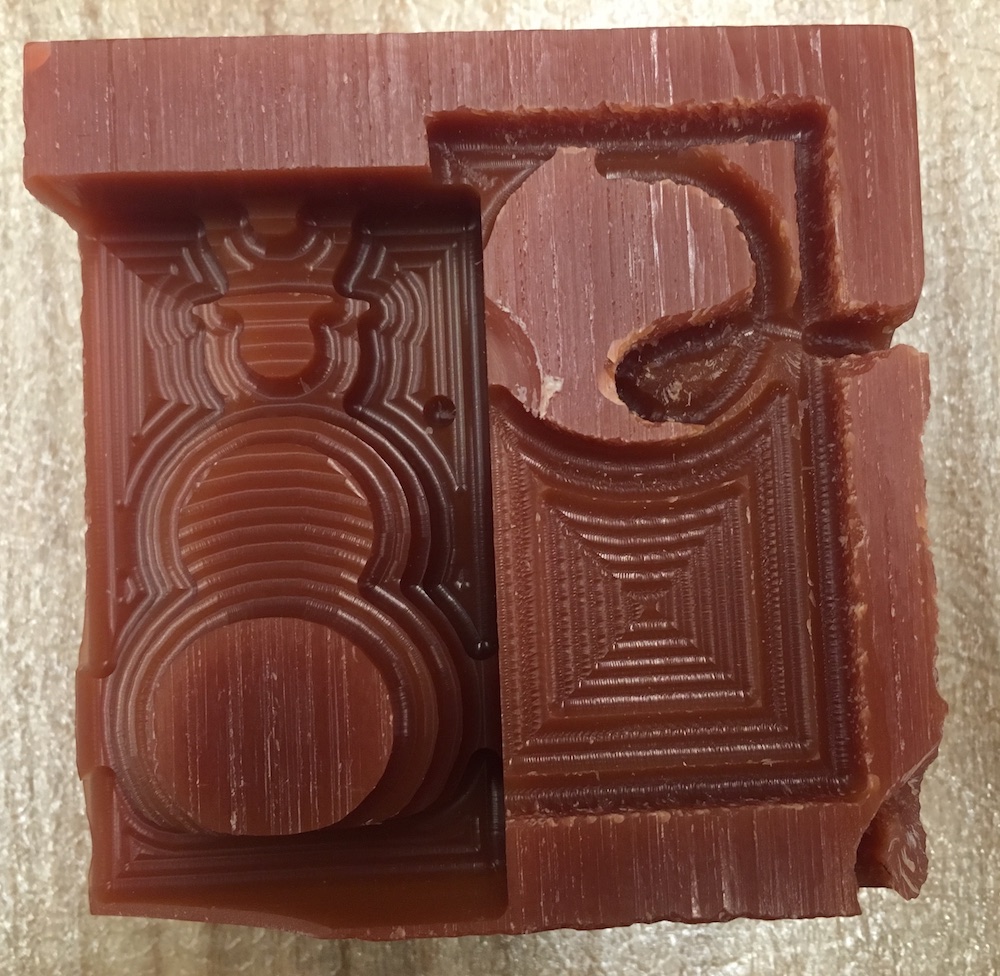
For each half of the mold, I used a rough cut and a finishing cut to achieve a smooth finish. Using the 1/8" ball endmill, I was able to produce some pretty nice molds. Once I got the hang of things and the settings down for the fabmodule, the entire process took about an hour. Unfortunately, some of the features on my model were too fine to be cut out with the 1/8" ball endmill. Additionally, there were issues in the toolpath generated when I tried to select "ball end" for the tool type with the "foam finish cut (1/8)" process, and therefore I had to select "flat end" for the tool type, which resulted in the loss of the placement bumps and corresponding holes on each mold half.
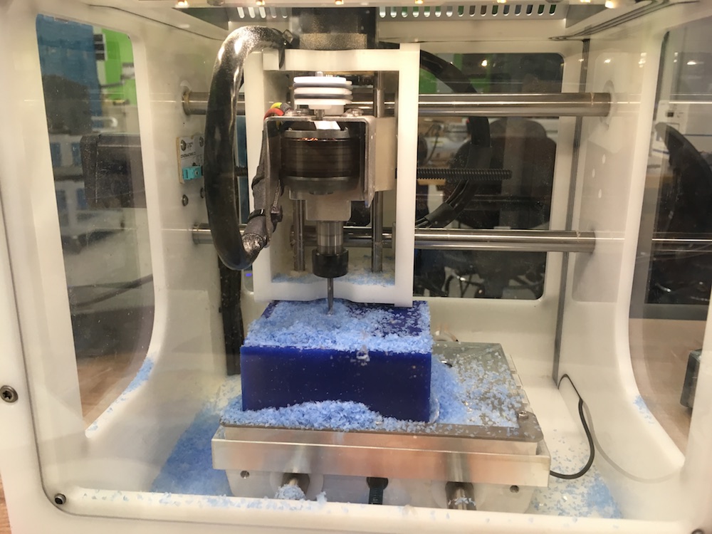
// othermill in action! // |
// rough cut of back mold complete // |
// finish cut of back mold complete // |
// full mold complete //
07.04 // casting the negative mold
The next part of the project is to use the machined mold to cast a negative mold. One issue I had with my machined mold was that the sides were not tall enough to really hold the mold liquid. Therefore, I quickly laser cut a press-fit box out of acrylic that could fit exactly around my machined mold.
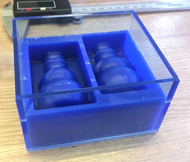
// full mold with acrylic box //
Next, I used OOMOO, a silicone mold making rubber. This mold comes in two parts, Part A and B, and they have to be mixed in a 1:1.3 ratio. Once you pour the two parts together, you have about 15 minutes before it begins to set. I was able to mix it pretty well, without getting too many bubbles in. I then poured it into my mold and tapped the sides a lot in order to get as many of the bubbles to rise to the surface as possible.
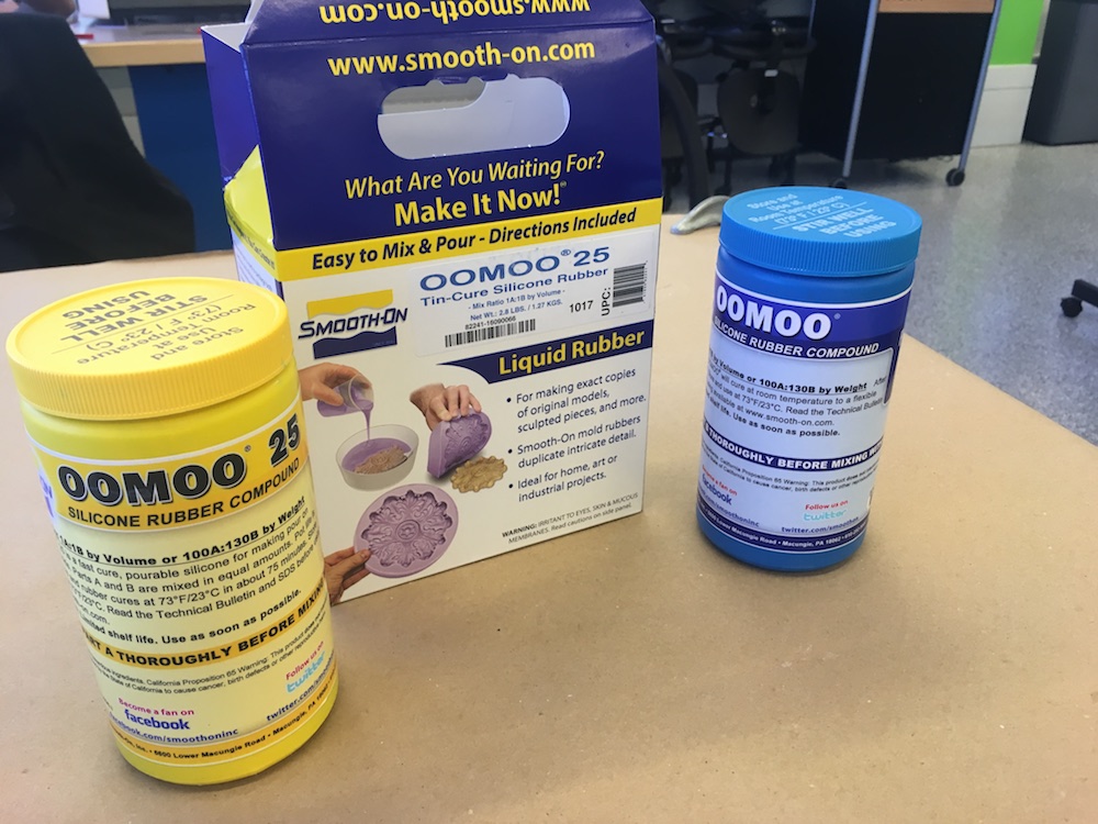
// oomoo // |
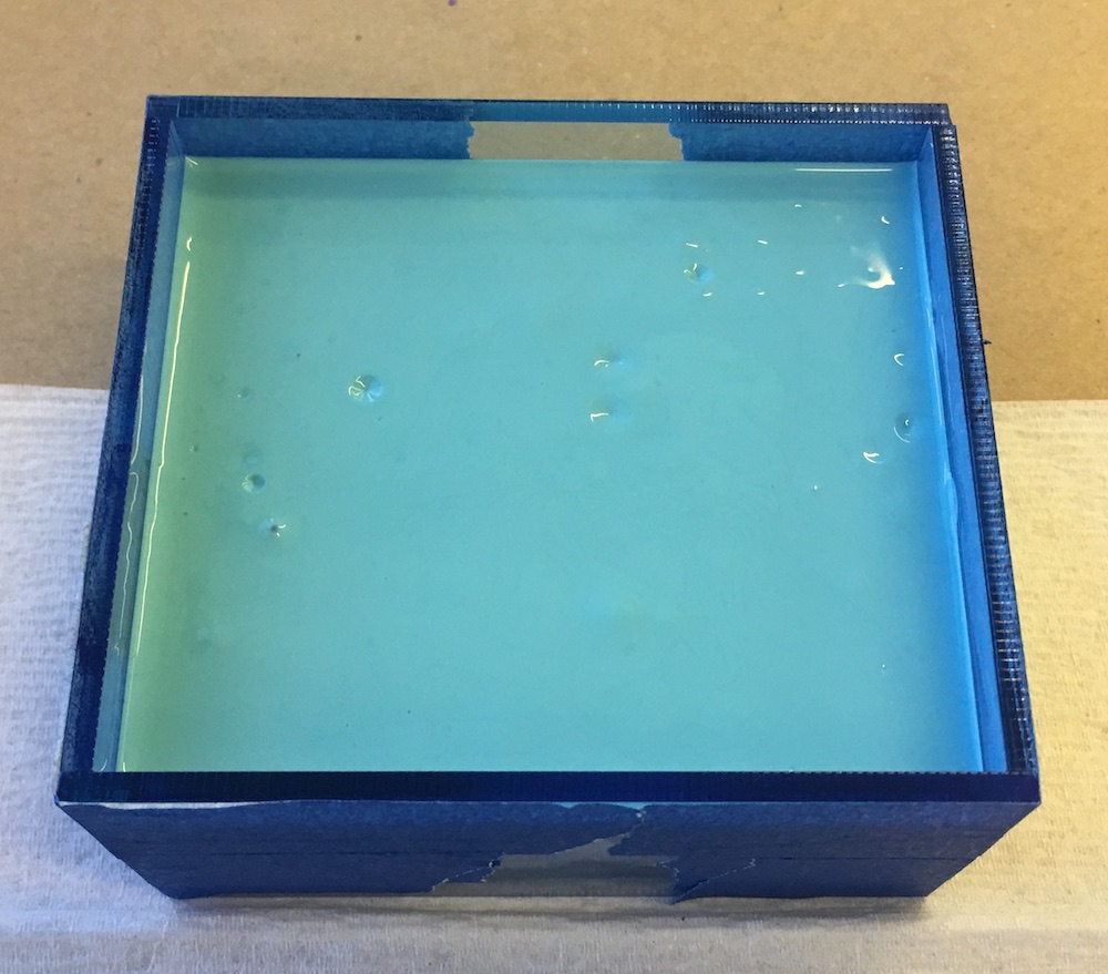
// oomoo poured into the mold // |
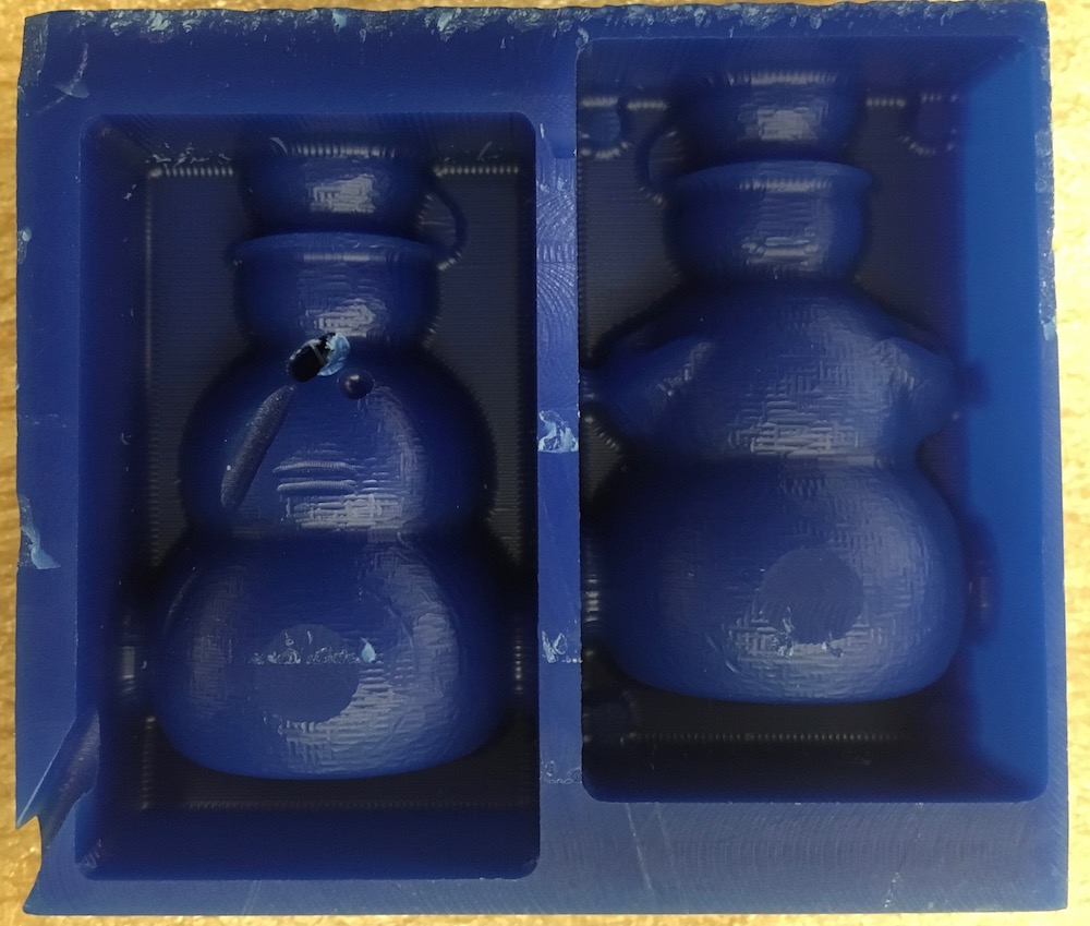
I made a point to really tap the edges of the mold in order to make sure all the bubbles in the Oomoo rose to the surface, and it looks like that worked well!
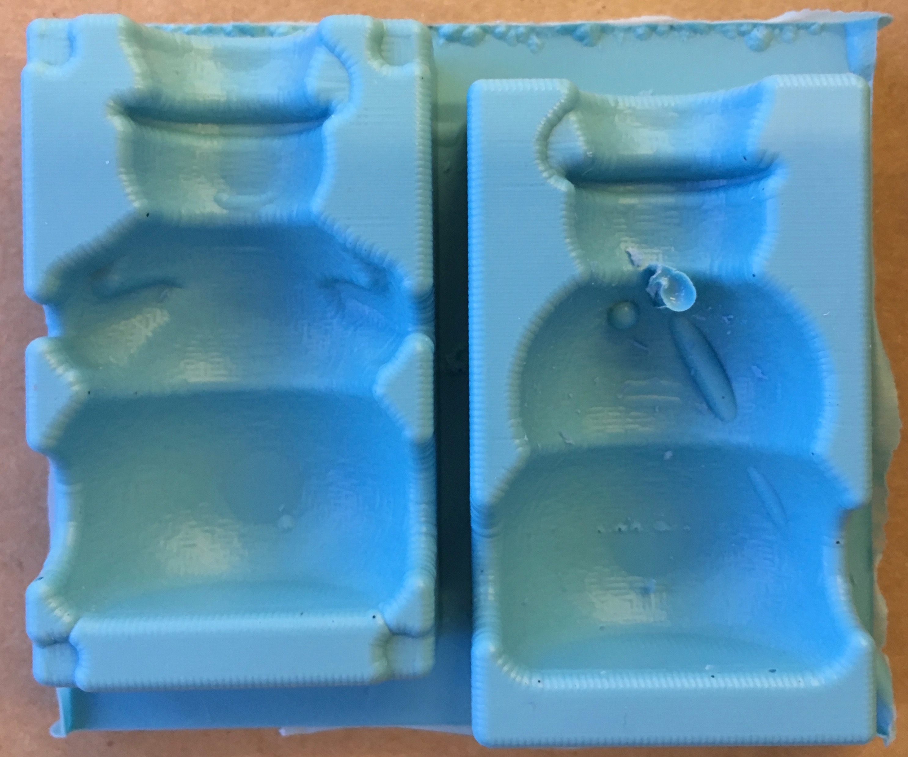
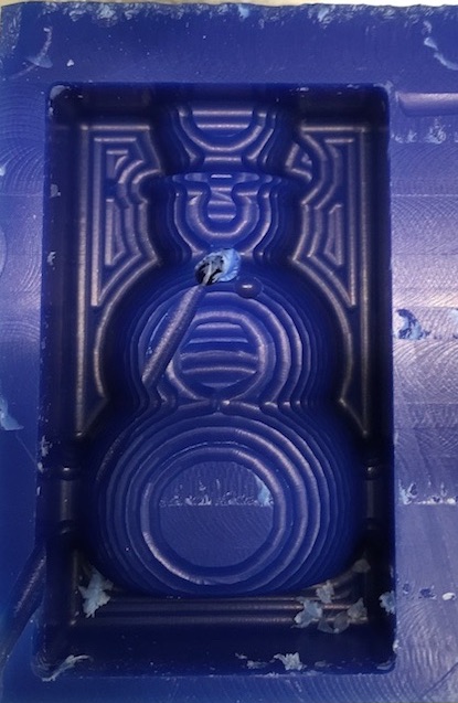
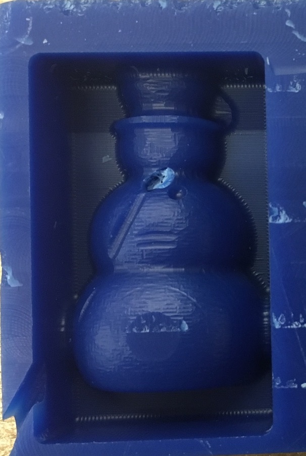
// final oomoo mold! //
07.05 // casting the final part
Unfortunately, my Oomoo mold was not ready to use as is because there was more than one opening around the mold due to their being minimal amount of space between the shape and the edge of the mold. So, I had to fashion some sides so the plaster did not pour out from the sides of the snowman! Additionally, the mating feature between the two halves of the mold was unfortunately too small to be machined on the OtherMill with the 1/8" diameter tool, so I also had to figure out the best way to mate the two halves to ensure the snowman came out correctly...