This week’s assignment was pretty straightforward - we were provided some traces and we had to mill our own PCB and then solder components onto it. The hardest part for me was milling the PCB - I spent a lot of time trying to get the Roland SRM 20 to work properly. One of the reasons behind this is that there were settings in the FabModules that weren’t so clear to me - like what the “jog” value was for.
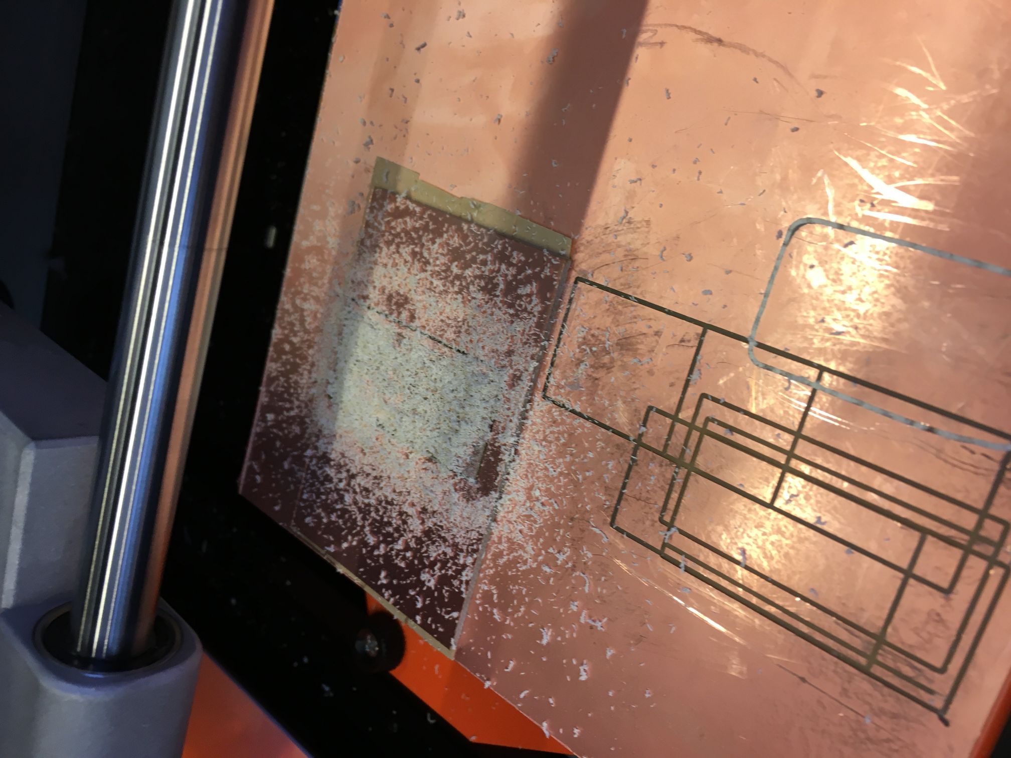
I had originally assumed incorrectly that the “jog” value was only for when we were trying to move the printing head to the origin, but I soon found out that the “jog” value is the height that the mill uses when it is going from one trace to another. Thus, I have some scratches on my board from when it went straight across traces to start making the new trace.
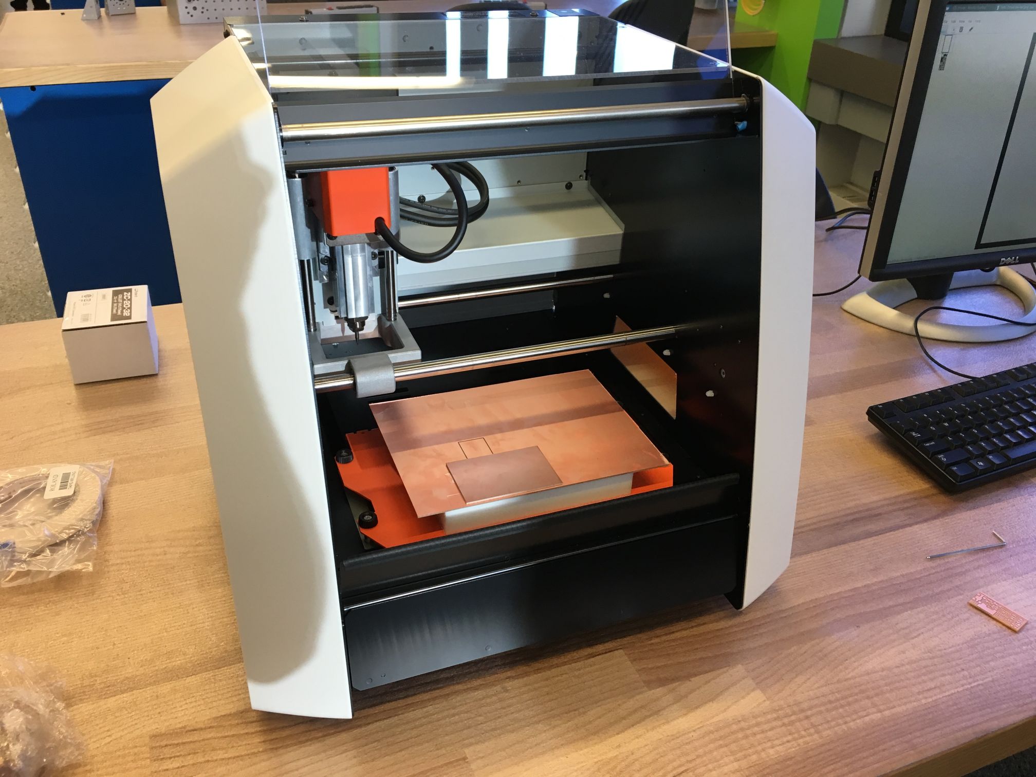
Some of the other things I learned was where to place the board on the milling platform. I had originally placed it too far right so that it wasn’t able to apply the necessary force (because the plastic block below the board was not there under it and so it didn’t have enough strength to hold itself up) and so the trace wasn’t deep enough and I had to restart.
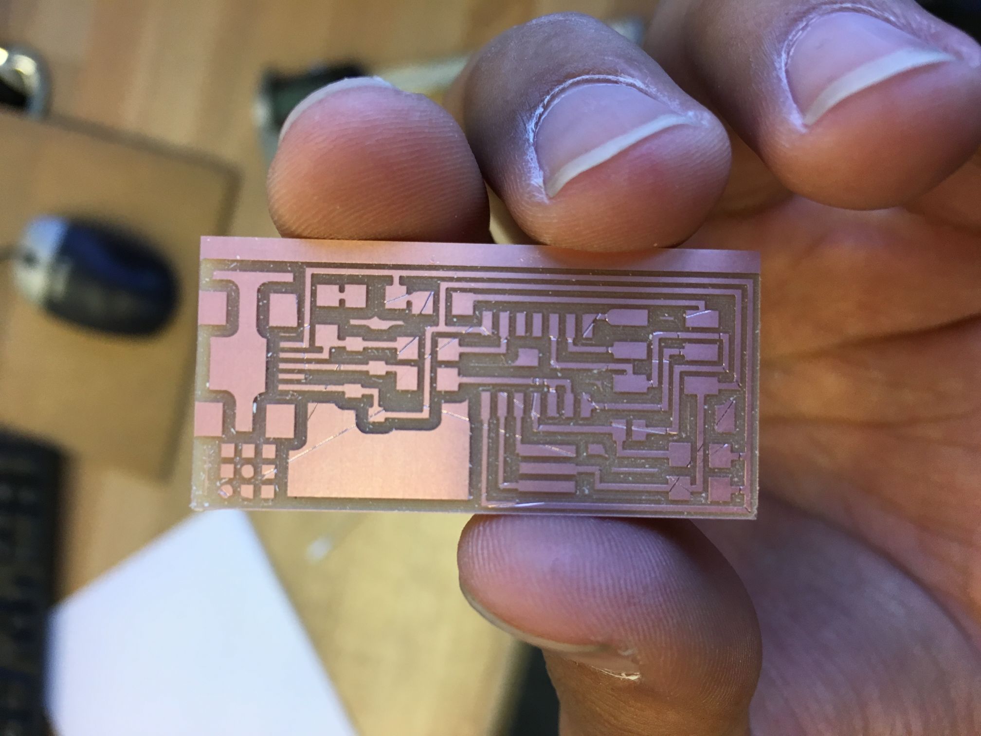
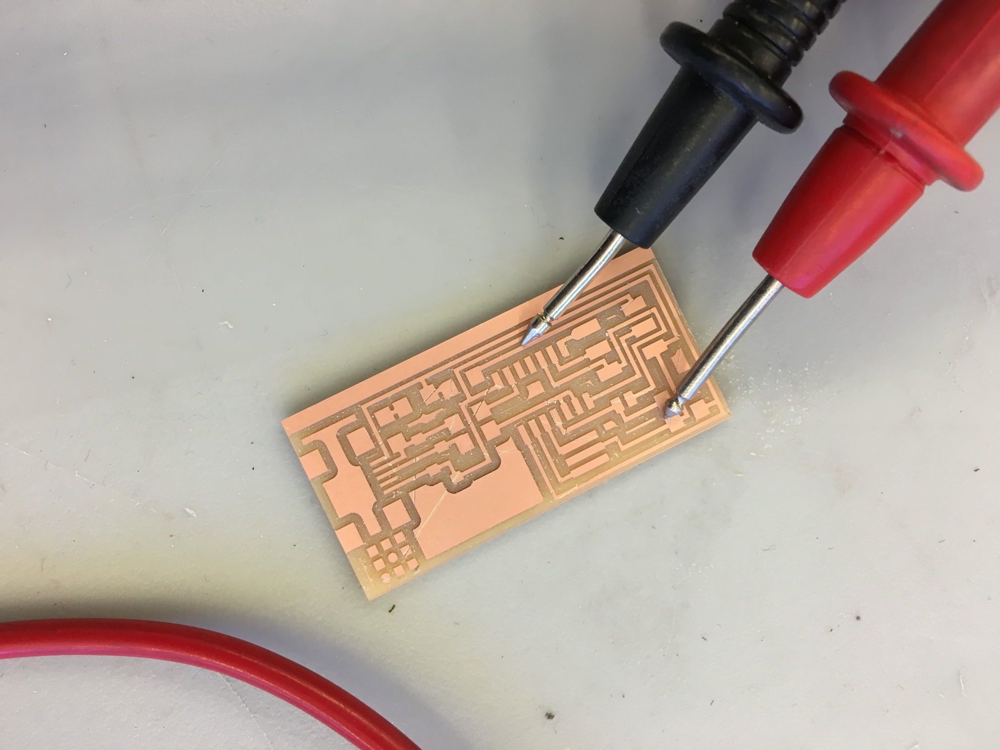
Finally, I got a successful cut and was able to test the traces to see if they worked. Here’s where I ended up placing the board during the good cut.
This resulted in amazing traces!
To check that the traces were right, I used a multimeter and turned it to the sound setting, which basically makes a noise if two wires are connected.
I’m still working on soldering the components onto the PCB - so more to come soon!
Update
I’ve now soldered the components onto the PCB. I actually re-did the board so that it didn’t use the 3 pin resonator as we saw that it had a lot of trouble maintaining the proper clock cycles to run a real USB interface, and thus we were suggested to use the 2 pin crystals.
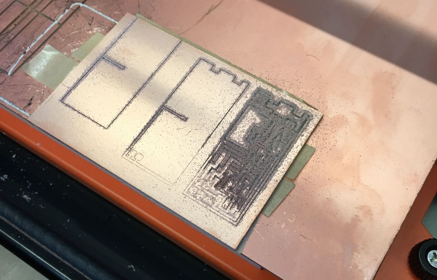
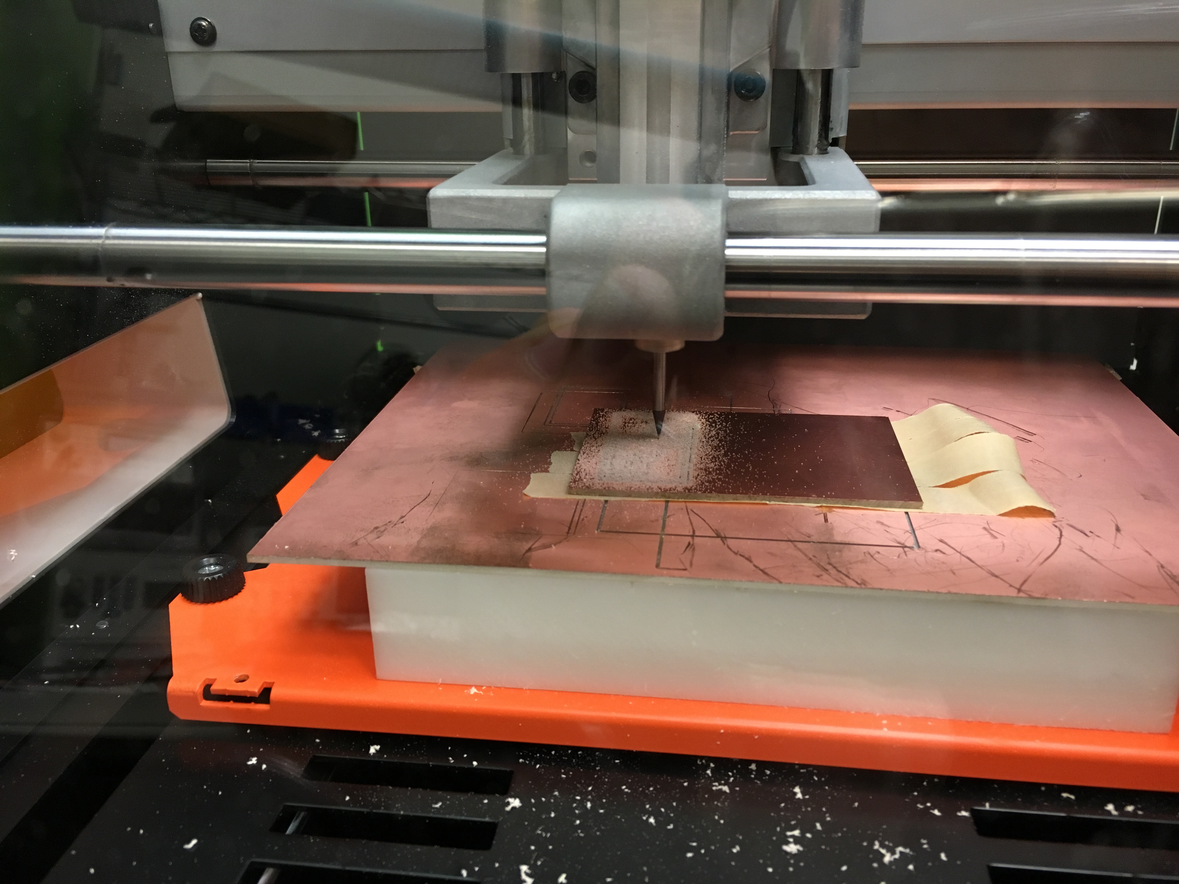
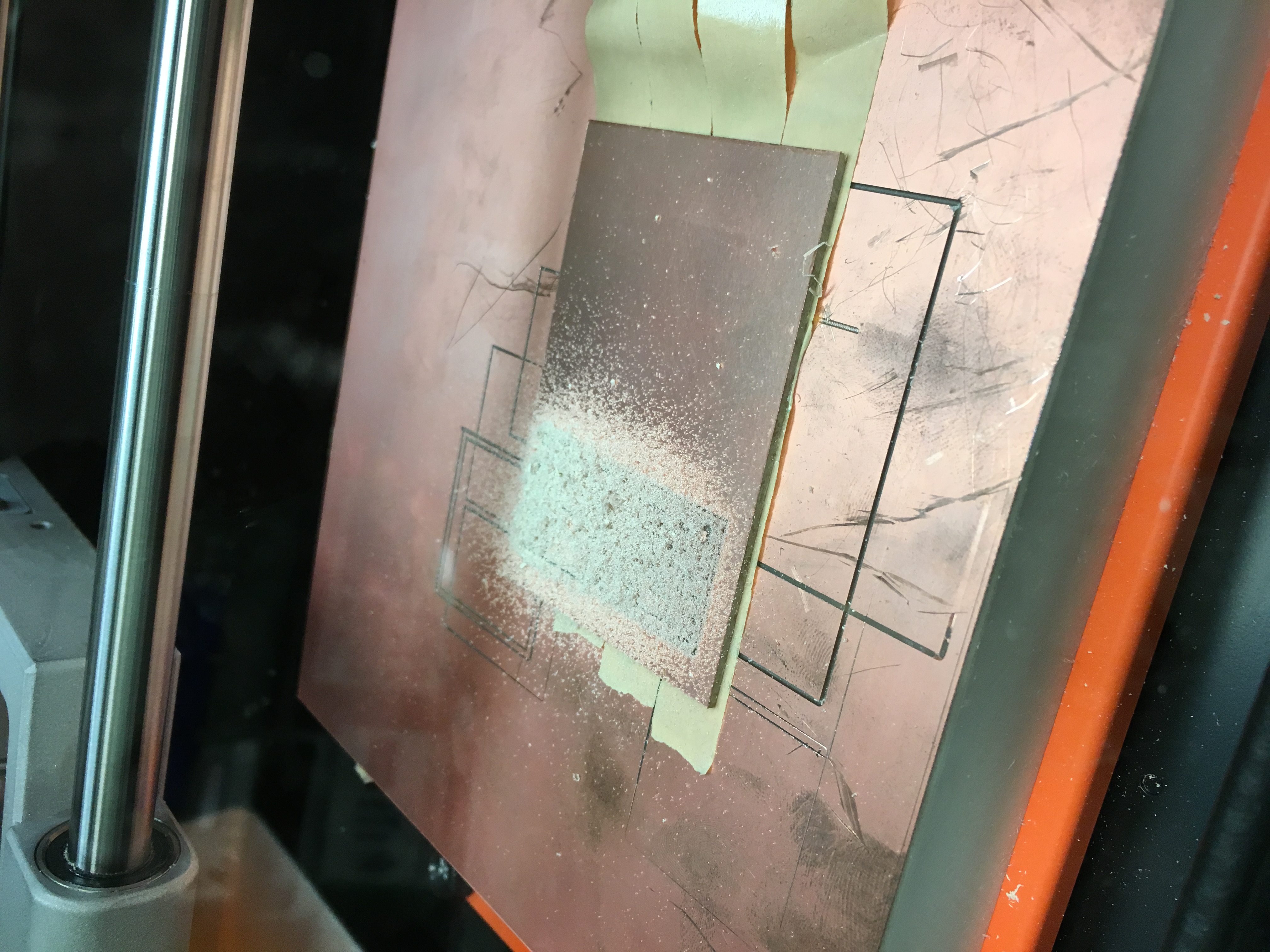
New board being milled:
New board filled in:
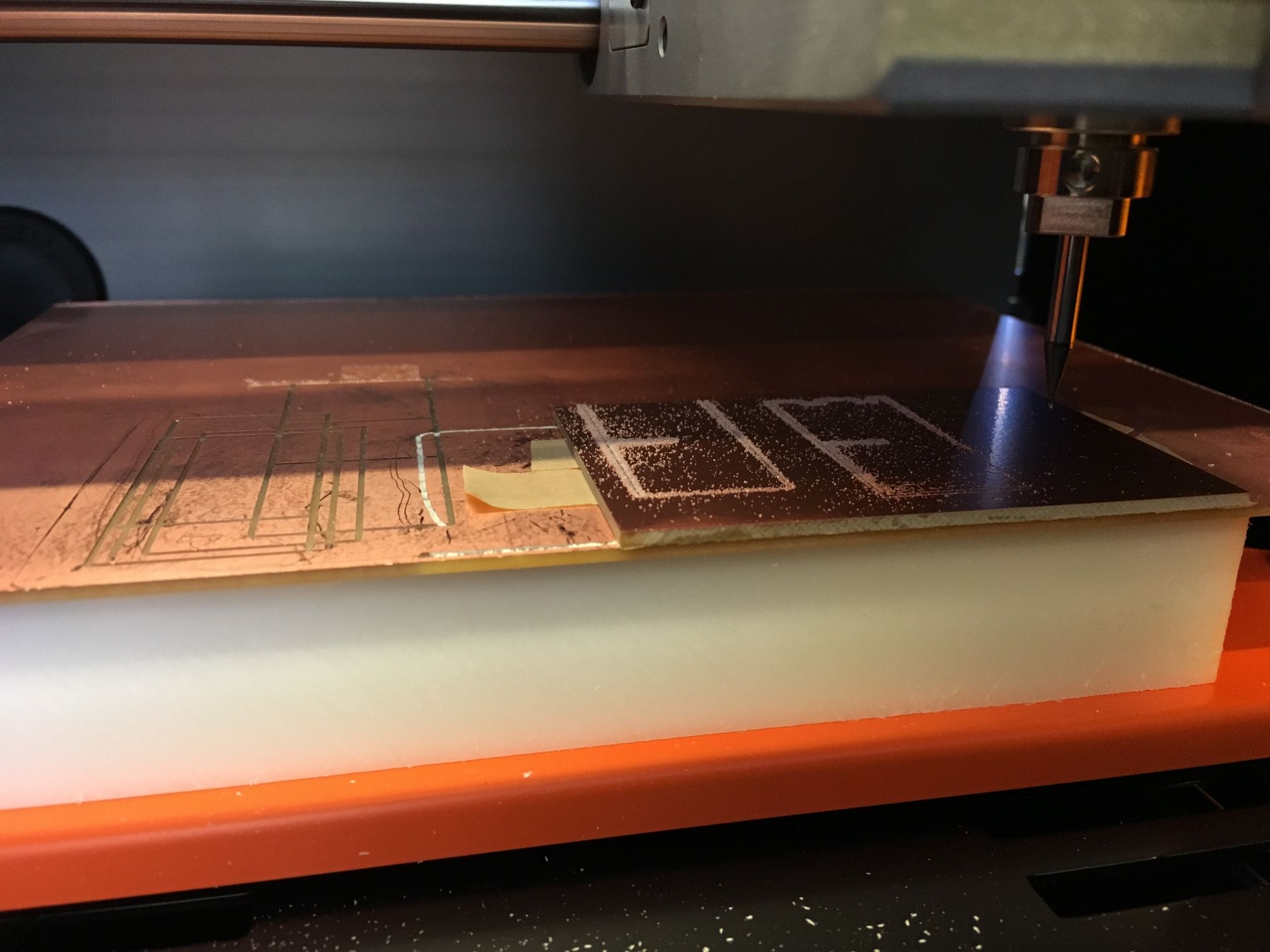
Cutting the board:
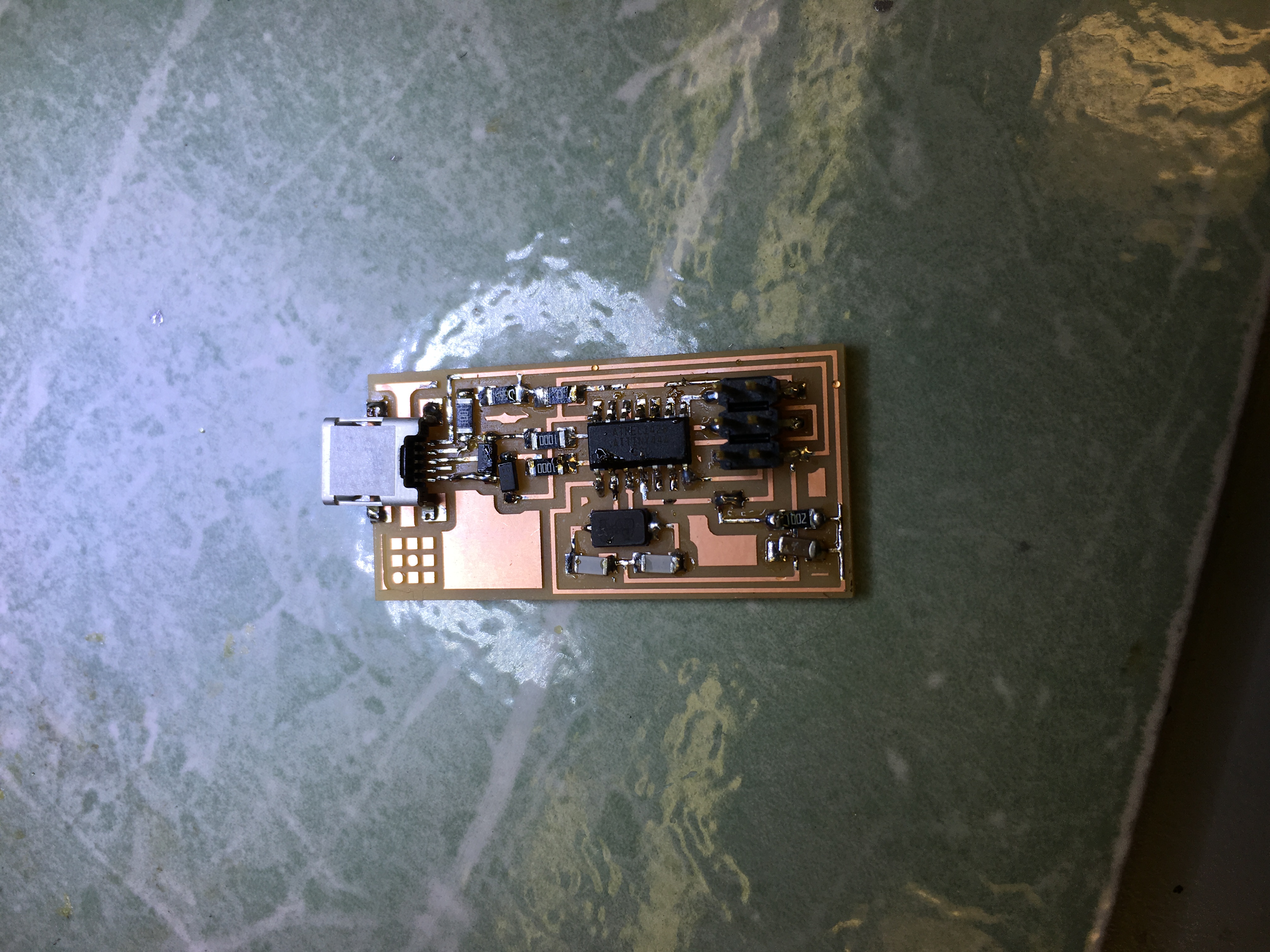
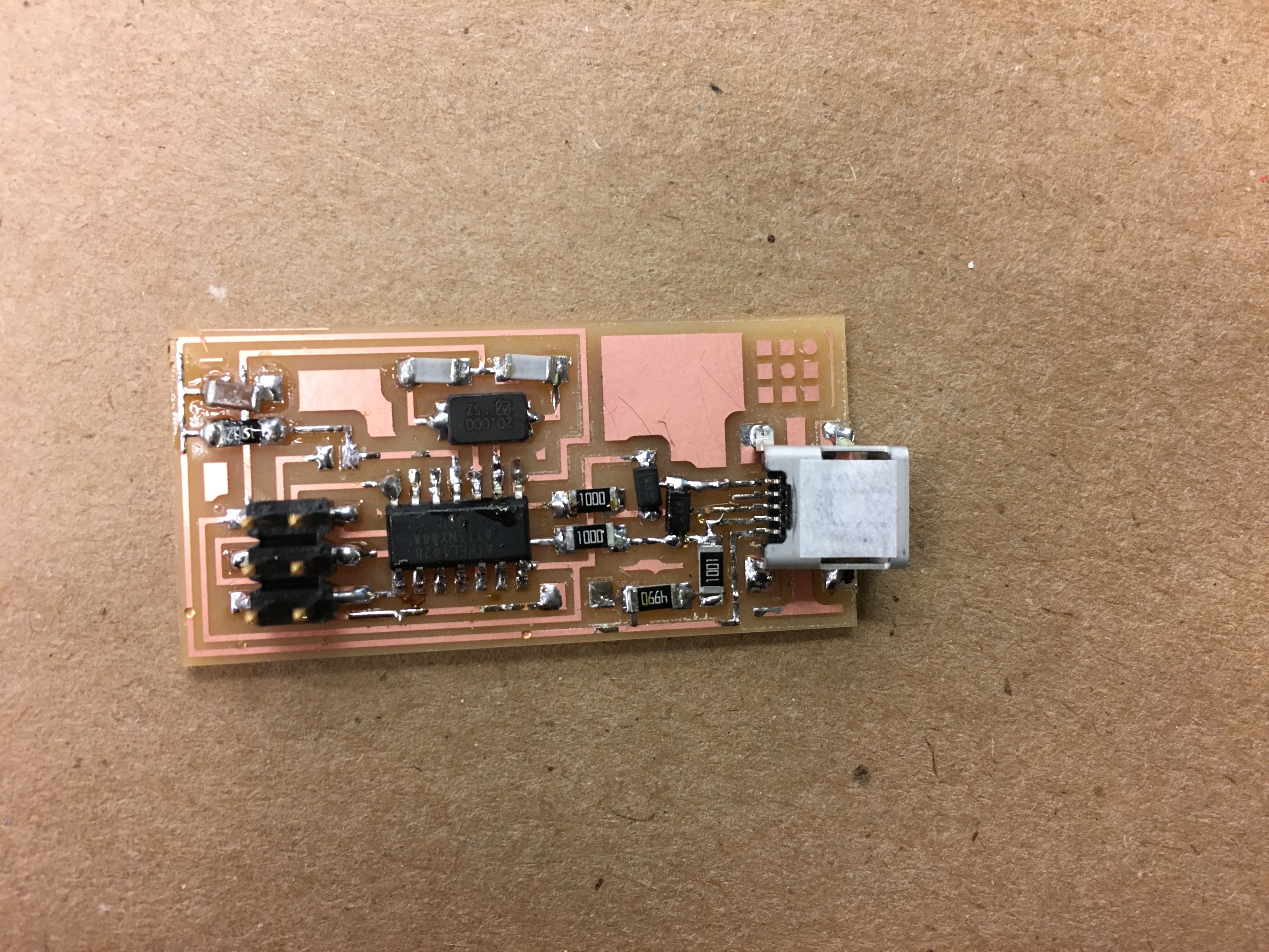
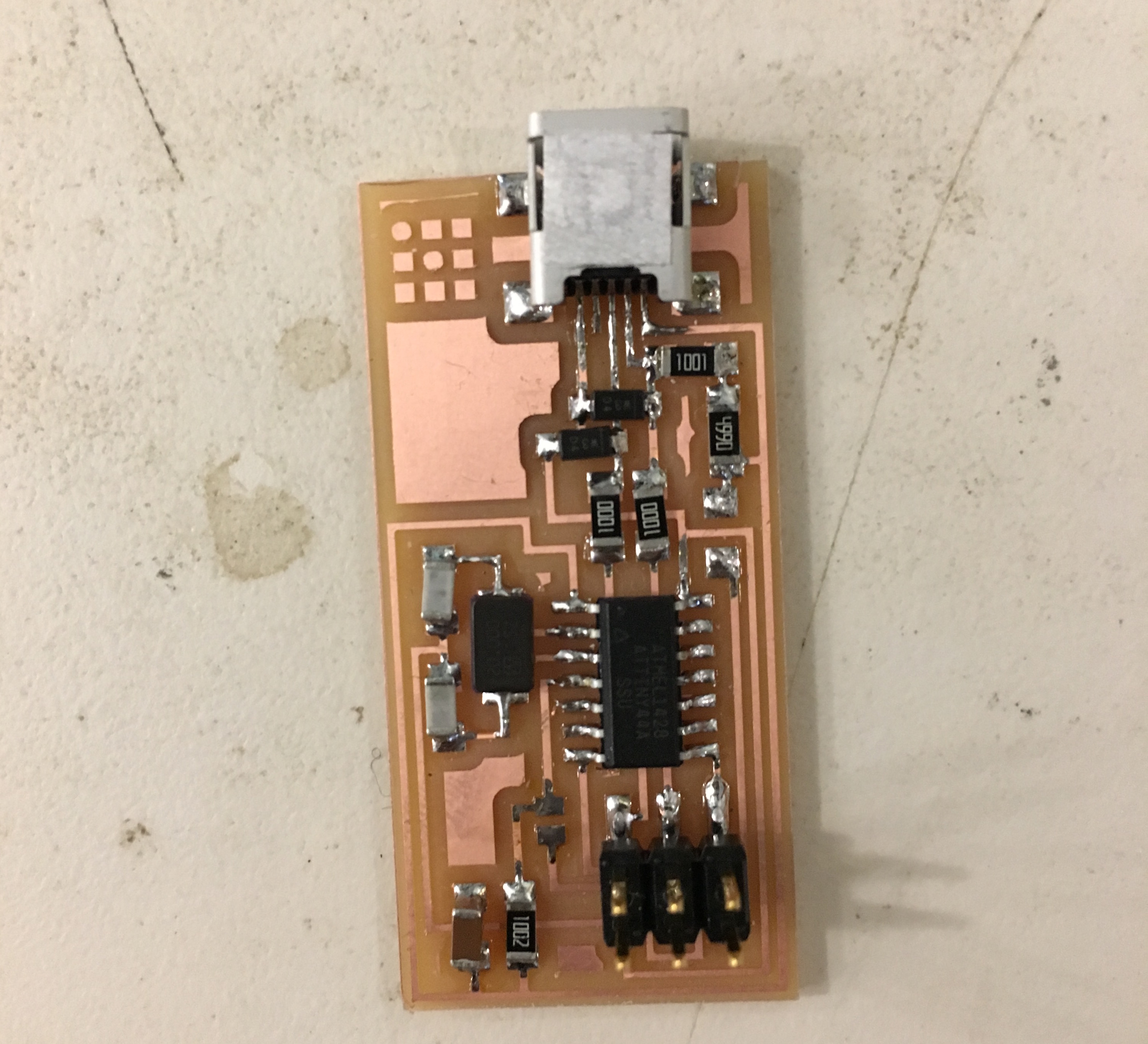
Once the board was milled, I just needed to stuff it. Here are two different views of the stuffed board.
The board programmed correctly but won’t be recognized by my computer in the System Profiler. I’m still trying to debug what went wrong!
Update #2
After going through 4 different boards with a variety of shorts and things, I finally came up with a successful board. It programmed but after programming, would only occasionally show up in the System Profiler. I guessed that it might be a weak connection problem and thus applied a lot more solder to the various connections.
Afterwards, huzzah! My programmer worked and I could use it to program other boards :)
Major Learnings
- Always be really careful when applying solder and check constantly for shorts. It’ll save you a lot of time later :)
- Use solder paste if the connections are hard to reach since it can help contain where the solder goes
- Work from the inside out - get the harder components early on so that you’re not potentially frying other components later on when adding additional ones.
- Check the orientation of all of your parts!!! Diodes go in a certain way as to microcontrollers :)