For this week’s assignment, we were tasked with learning Eagle so we would be more proficient in the future when we need to create our own boards. We had to modify Neil’s Hello World board and then add our own LED and button to it. The best way that I found to do this was to first take the schematic for Neil’s board and then recreate it in Eagle. I also followed along other tutorials on Sparkfun and past student’s pages to figure out the best way to go about doing this.
I struggled with learning how to use Eagle – it was a very unintuitive interface. One of the biggest issues for me was finding all the parts and adding them to the schematic. Also, with that, there are two different options for wires in Eagle, wires and nets. If you use a wire, it doesn’t actually result in connections being made and thus these connections don’t show up in the board view when you try to route the traces.
This tutorial is by far one of the best ones out there to get started.
First, when you start with a new project, make sure to add in the Fab libraries (fab.lbr) and update the design rules with fab.dru so that we can mill out our boards with no problems.
Next, wire up all the various components using “Net” components, and drag the parts around to make sure they’re actually connected.
After doing this, go ahead and switch to the board view by clicking on the button - it’s important to click the button in the main view to guarantee that any changes made to the schematic propagate over to the board and vice versa.
In the board view, you’ll see all the connections made in the schematic view with yellow lines. After this, we can either manually route all the connections or use the autorouter. We can also make sure that the wire trace width is at least 16 mils as that is what is required to be able to cut out the traces with the 1/64 end mill.
Here are some screenshots of my process of creating the board in Eagle:
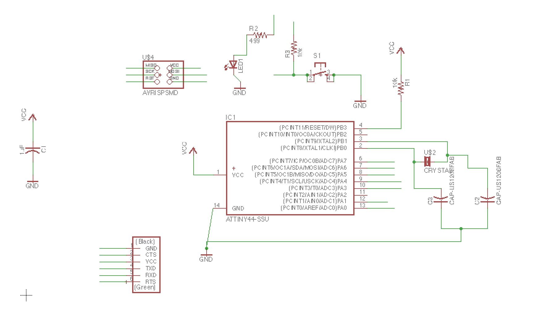
Schematic:
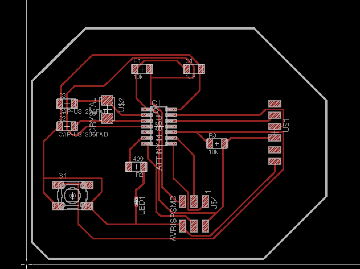
Board after autorouting:
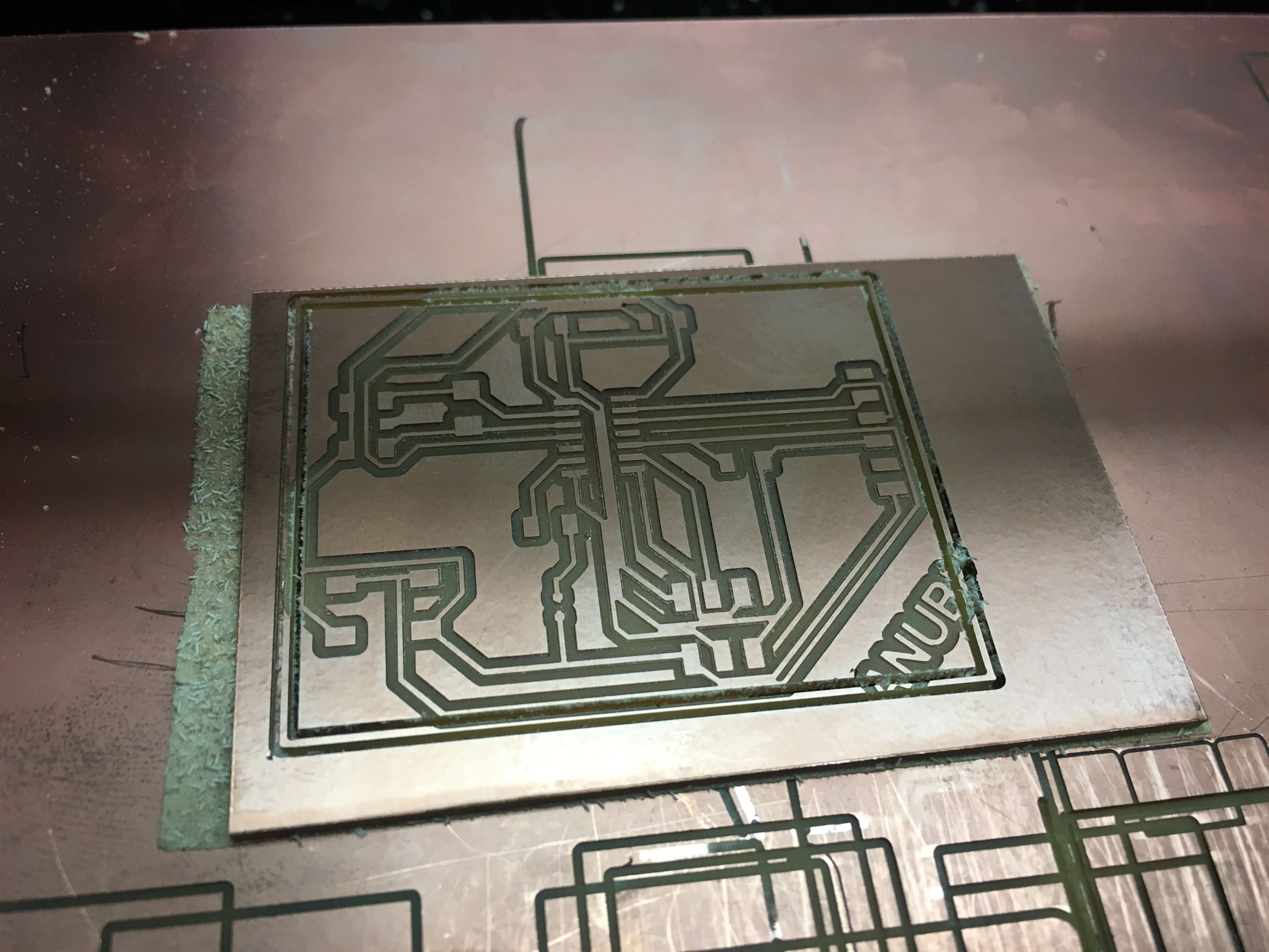
One of the mistakes of autorouting was that it didn’t leave enough of spacing in between multiple traces, as can be seen in the final cut board below.
My first attempt at cutting wasn’t super succesful - the board wasn’t down very well and thus resulted in a really poor cut. I ended up ending the job and starting over.
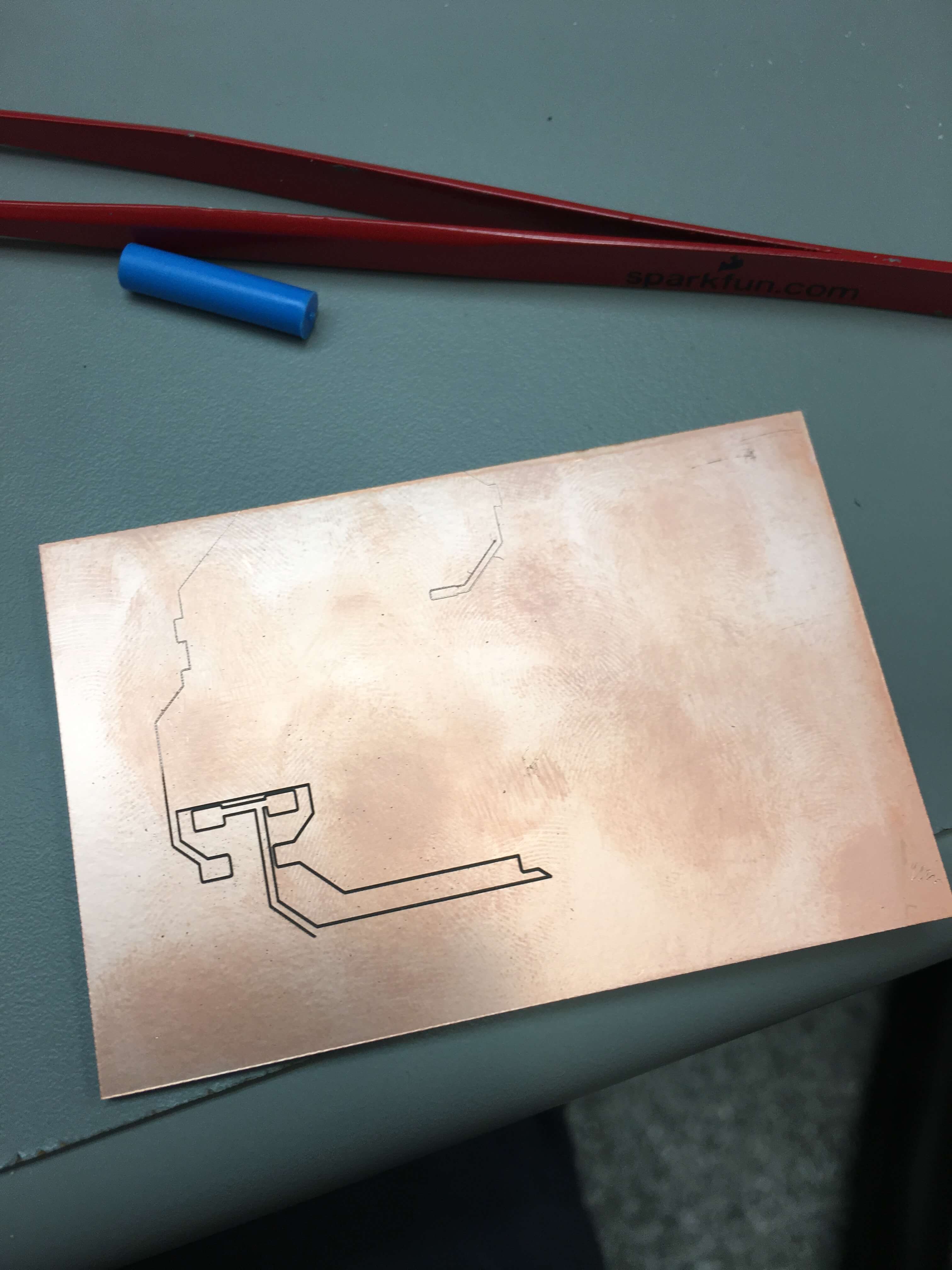
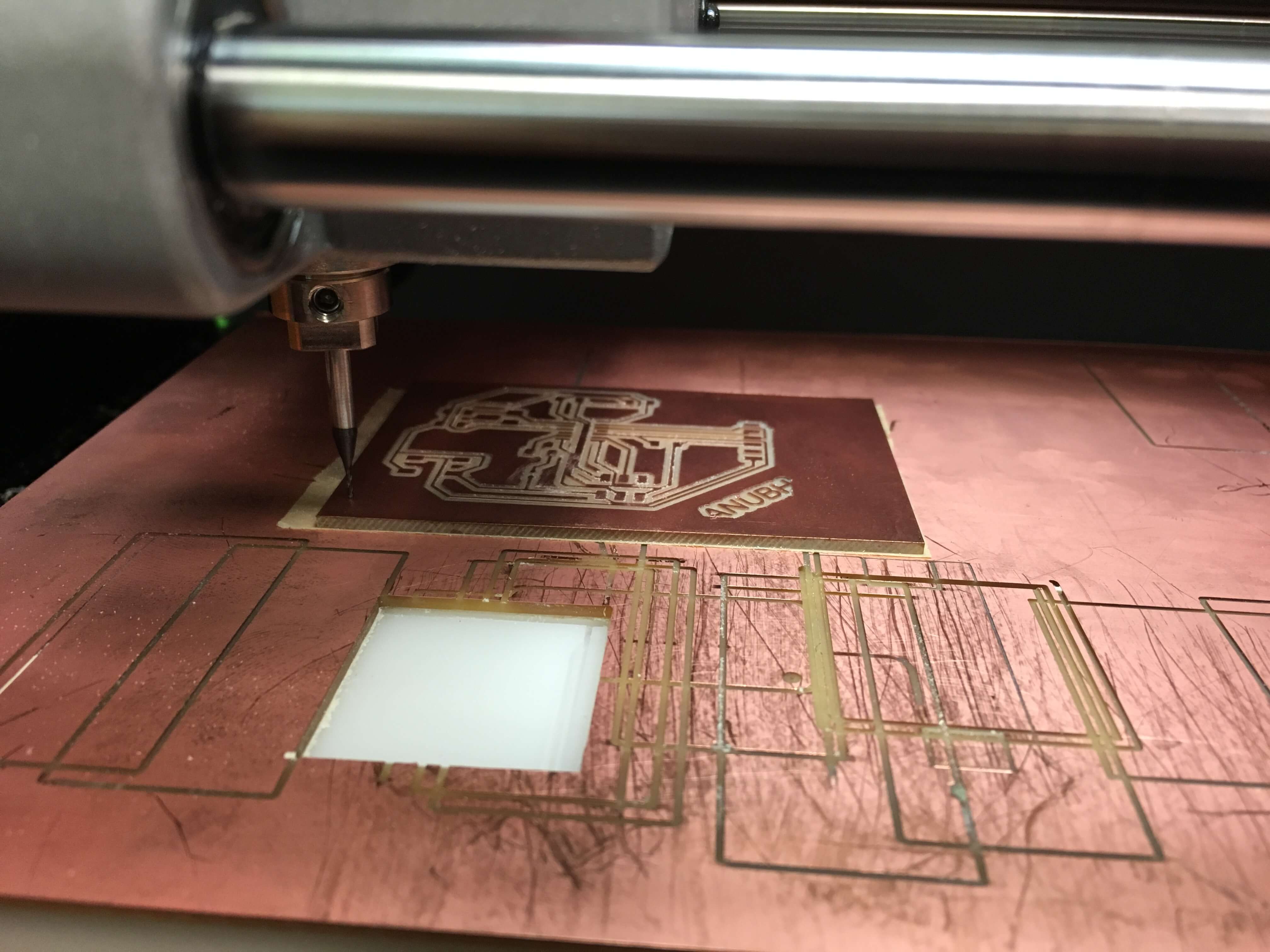
The next try through, the board seemed to mill really well.
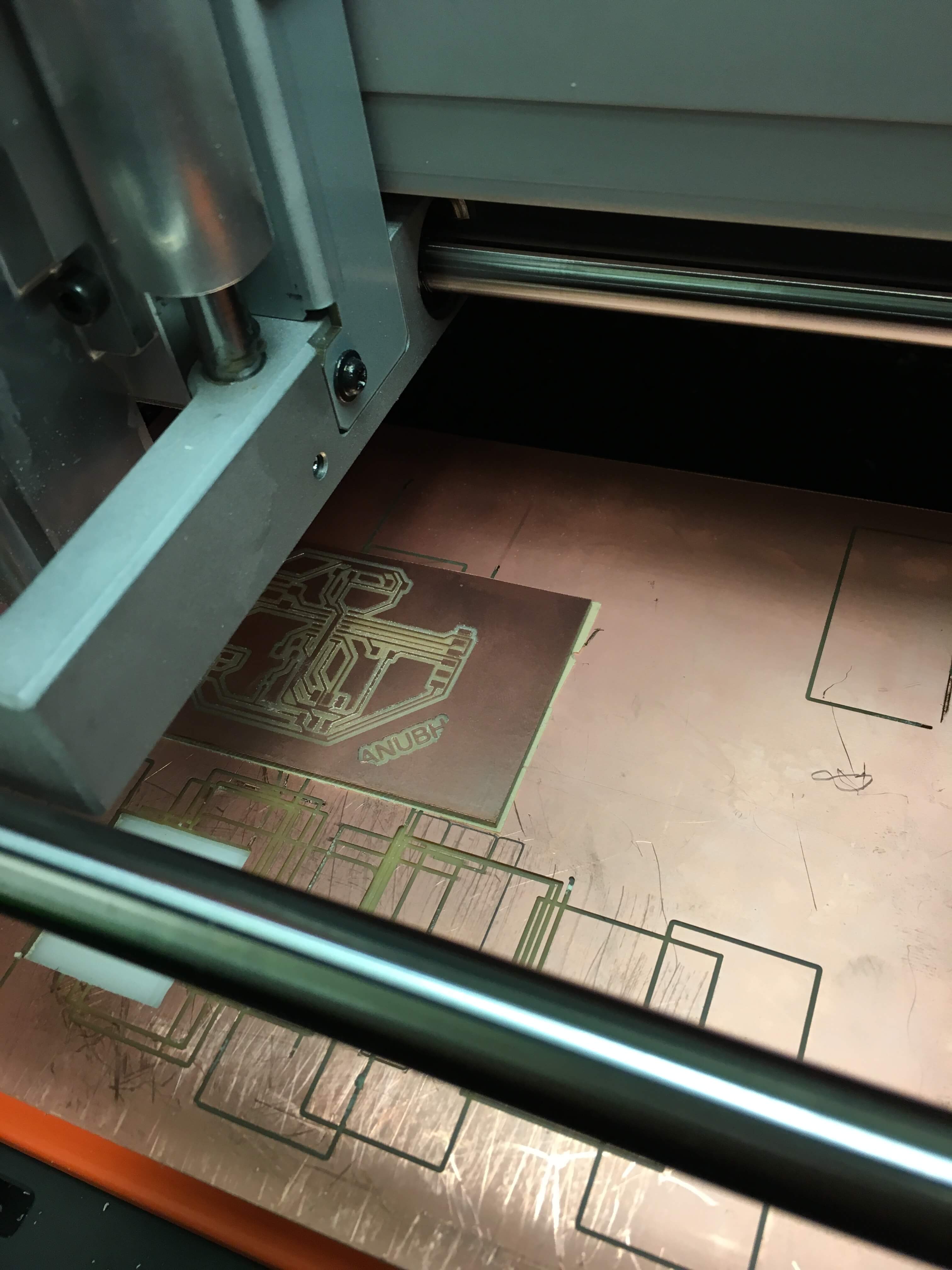
Here’s an image of it in the middle of the process:

I even put my name in the corner to customize the board even more.
Right before cutting it out, this is what the board looked like. It looks so clean - I didn’t initially realize that there were any issues until I looked closer at the end (see more below):
As can be seen below, the final board had many different issues. First, the traces in the center are fused together. Second, the outside didn’t cut in one line, but has two separate cuts, which caused it to cut into certain traces. These were both issues that I didn’t realize could be problems and will have to work on fixing going forward. I think the first problem is actually because the DRU doesn’t prevent the autorouter from routing the traces too close - maybe there will be a way I can fix that or otherwise I’ll route them manually next time!