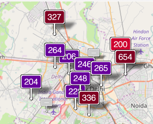
For my final project, I’m building a connected Internet of Things PM 2.5 sensor to be able to create a low cost way to track pollution levels in Asia and other countries. This was motivated because about a month ago, India’s capital and where most of my relatives live, New Delhi, had such a high pollution concentration that kids were told not to go outdoors and schools were closed for 3 days. This frightened me, but what was worse was that the only charts I could see of the pollution levels showed a total of 8 answers deployed in New Delhi.
 https://www.theguardian.com/world/2016/nov/06/delhi-air-pollution-closes-schools-for-three-days
Creating a PM 2.5 Sensor
I essentially wanted to create my own version of http://aqicn.org/city/india/new-delhi/us-embassy/ as it provides exactly what I wanted to see. I looked online and found this sensor from Digikey, made by Sharp.
It came with a spec sheet.
The sensor’s datasheet is pretty hard to read, as it is in Mandarin and in English but doesn’t really explain as much as it should. After having read it over 4 times, I think I finally understand how to use it. My plan is to use the ESP 8266 Wi-Fi chip’s onboard ADC to sample the voltage coming out of the PM 2.5 sensor, use a BME 280 temperature, pressure and humidity chip to measure those values consistently, and then combine the data together to calculate PM 2.5 concentration from the output voltage of the PM 2.5 sensor.

Initial Steps
The first thing I did to start creating my connected PM 2.5 sensor was to try to make the circuit. I wanted to make sure we had all the components I needed and how they’d fit together to figure out the size of circuits, this would determine the form factor of the physical manifestation as well.
I started by looking at the most complicated part of the circuit, the pollution sensor.
Here’s the circuit block diagram from the datasheet:
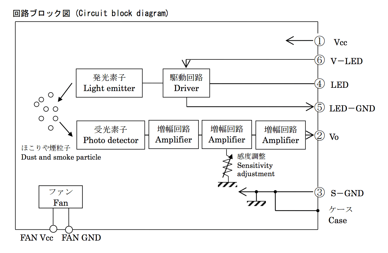
From here, it seems to make sense. Pin 1/3 is to provide VCC (5V)/GND to the sensor, while pins 5/6 provide power to the LED driving circuit. Pin 2 is the voltage output from the sensor. However, what was very confusing was the use of Pin 4 (LED), and why the circuit needed a separate power circuit for the LED driver.
The only other diagram from the datasheet that helped with this was the following:
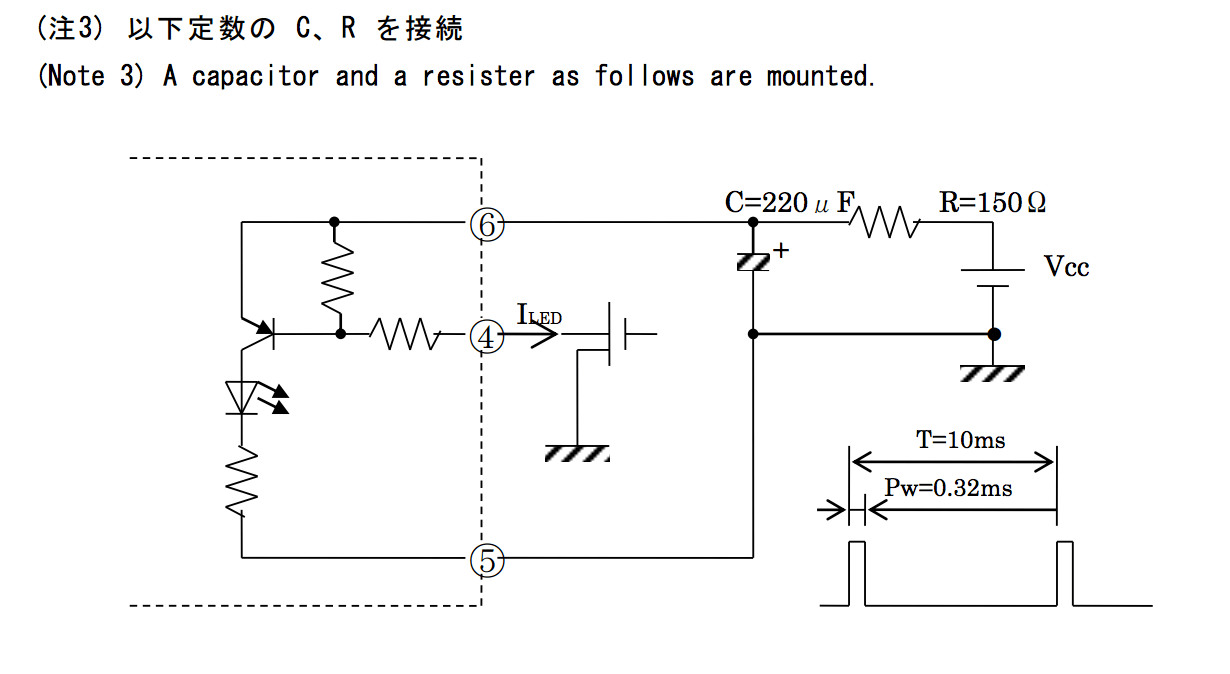
From here, we can see that there is an RC circuit on the input voltage for the LED. I was initially confused about this, and spent multiple days trying to understand what was going on. However, after talking to the TAs and others in the lab (thanks Nick and Gavin!), I was able to learn that the RC circuit was essentially constructed to add a lot of power into the LED for a brief period of time. There were also very strict timing requirements with this circuit, I should poll the sensor every 10 ms, and sample after 0.28ms after having flashed the LED. These weren’t immediately apparent to me either as it wasn’t explicit in the datasheet except for the bottom right corner of the above image.
Finally, something that isn’t clearly explained in the diagram above is that Pin 4 is actually an output pin from the sensor that has some current for the LED. When we want to turn the LED on, we ground that pin and discharge our capacitor into the LED. This turned out to be problematic - I had wanted to use the ESP-8266 to drive my circuit as it had an ADC and enough pins to do what I was looking to do - however, it runs at 3.3 V and the sensor operates at 5 V, and the pins on the ESP-8266 can’t accept voltages higher than 3.6 V and so I would need to level shift in between them.
I had already designed an initial board that used the ESP-8266 and had already down converted the input voltage from 5V to 1V since the ESP-8266 ADC only accepts voltages in the range of 0 - 1V. I also chose to use a MOSFET to drive the LED as I wouldn’t need to worry about burning out my ESP-8266 then.
Finally, another concern was that I would need to turn the fan on and off, but couldn’t do that with just 3.3V. I used another MOSFET (N-FET) to drive the fan circuit separately.
Game plan:
As Neil mentioned in lecture, he suggested following spiral development to be able to successively grow our projects and make sure we get something done. To do so, I followed the following game plan: 0) Design the circuit 1) Test the ESP-8266 and be able to communicate to it / using it 2) Test the BME-280 chip with the Arduino Uno to figure out I2C communication and see if the data coming back makes sense 3) Integrate the ESP-280 chip with the ESP-8266 chip to get temperature, humidity and pressure data going to the server [MVP - connected temperature sensor] 4) Test the Sharp PM 2.5 Sensor and fab out the control boards 5) Integrate the ESP-8266 with the PM 2.5 Sensor - sending pollution data to a server in the cloud 6) Integrate all three sensors together 7) Create a form factor to house the circuitry 8) Test the system in a real world scenarIO
Past Work
Late last week, I decided to see if anyone had actually used the sensor I was planning on using in creating a PM 2.5 pollution sensor. I was lucky enough to find two separate individuals that had used this sensor or similar ones to understand the LED circuit better.
Here are the two different projects I found: 1) Project using the same sensor as me but a Particle Photon 2) Project using a different Sharp air quality sensor and Arduino Fio
While these seemed similar to my project, I wanted to still go ahead as there were some differences. I would need to integrate my own temperature sensor, talk to the Wi-Fi through my own module and also create a housing for it. I also hoped to be able to eliminate the need for the Arduino/Particle and be able to reduce the cost of the materials.
Build of Materials and Tools Used
To make this project, I used the following materials (main parts):
- Sharp PM 2.5 Sensor (DN7C3CA006) ~$20
- BME 280 Temperature, Pressure and Relative Humidity Chip ~$10
- Sparkfun Bi-Directional Level Shifter (BOB-12009) ~$3
- ESP-826612E Wi-Fi Module $5
- Arduino Uno Rev 3 ($22)
Approximate total cost: ~60 + additional electrical component cost
Most of these parts were bought off of Digikey. The Sharp PM 2.5 sensor was purchased from Digikey, while the BME 280 chip was from Amazon and then I had one of the Sparkfun Level Shifters lying around. I chose to use this chip to save myself time and make progress instead of fabbing out my own, despite already having a schematic prepared and ready to be cut. We had the ESP 8266 and Arduino Uno in stock in our lab (see more below for process and decisions made).
Tools/Machines:
- Eagle
- Inkscape
- Rhino
- Corel Draw x7
- Vinyl Cutter
- Othermill
- Roland SRM-20
- Universal Laser Systems Laser Cutter
- Oscilloscope
- Volt meter
- Thermoformer
- Band-saw
Working with the ESP-8266
To begin, I started by experimenting with the ESP-8266. I used Yuval’s Week 13 as a starting point, as he had debugged a lot of the issues with the ESP-8266.
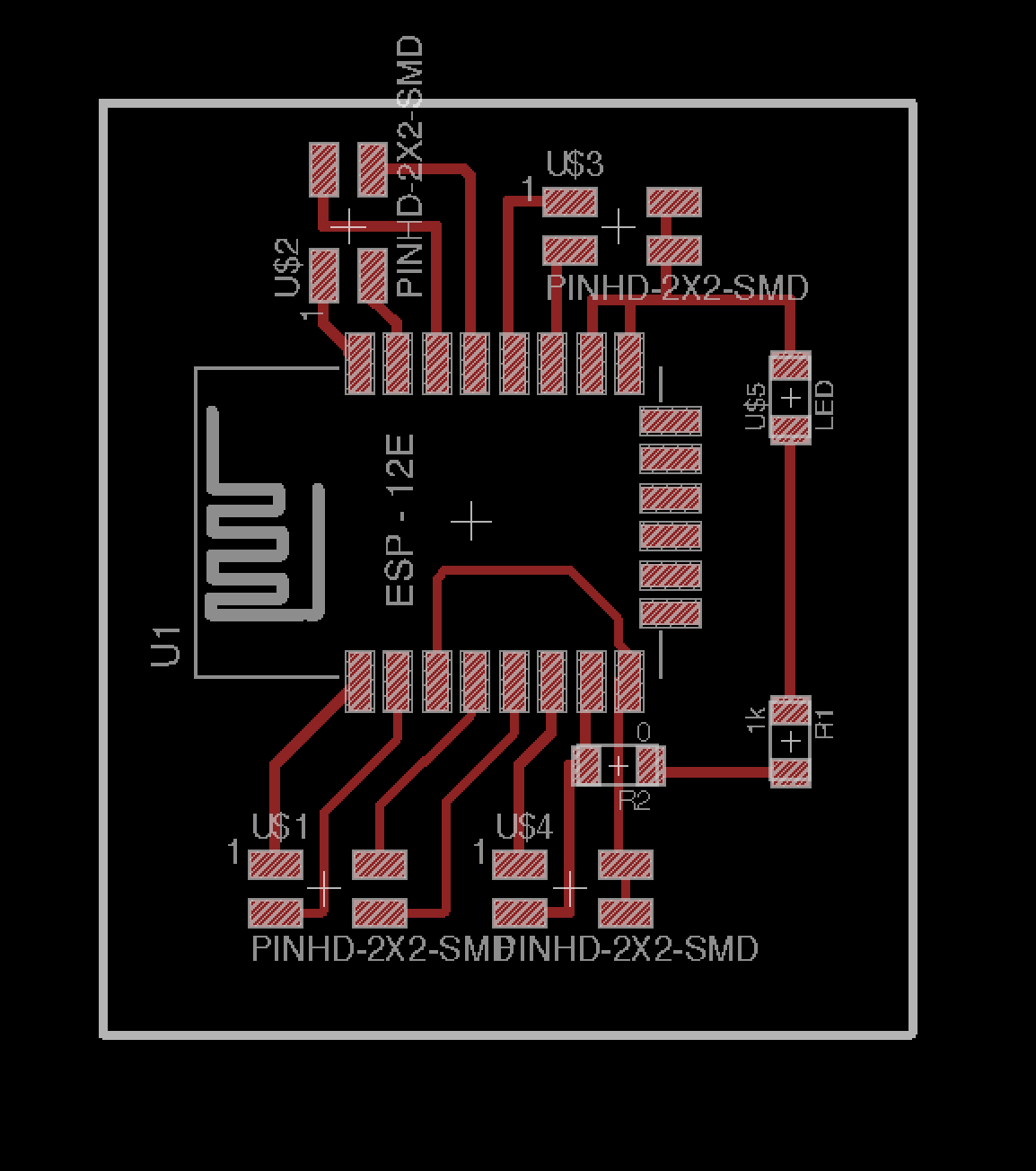
For my design, I decided to essentially fab my own breakout board, giving me access to all the pins as I would need this later to be able to work with the various components (temp & pollution sensors). I also made my own power board to supply the various voltages I would need from a 9V battery.
Here are what the designs for both looked like:
Wi-Fi Breakout board:
I knew that since I didn’t add buttons, I would need to jump a few cables to be able to reprogram the module, however I was willing to make this sacrifice to be able to get access to all the pins.
Power Board:
 .
.
Stuffed power board:
 The power board used two SOT223 regulators to shift the power down from 9V to 5V and 3.3V. I decided to include 2 headers for each of these voltages, which turned out to be very smart later on.
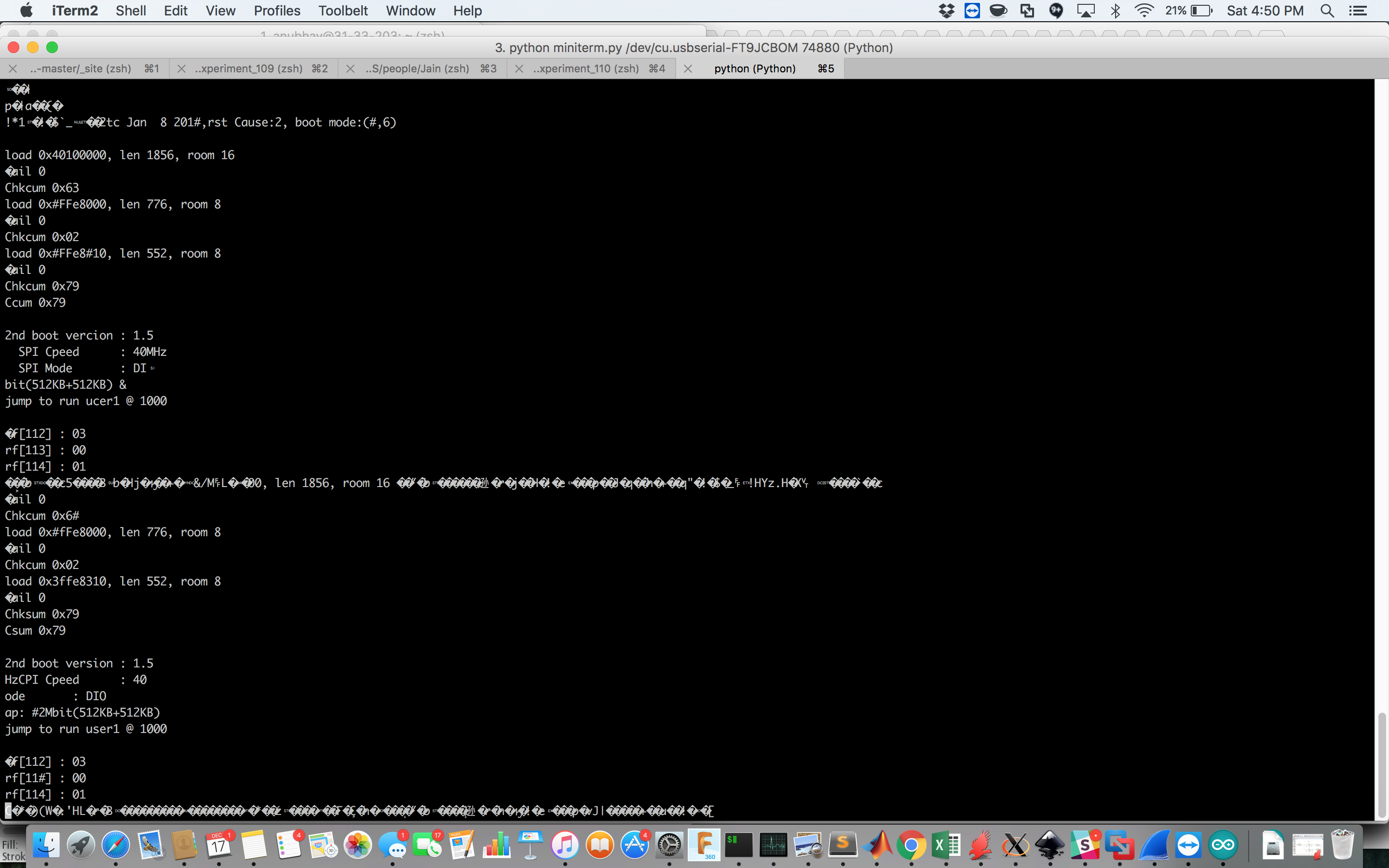
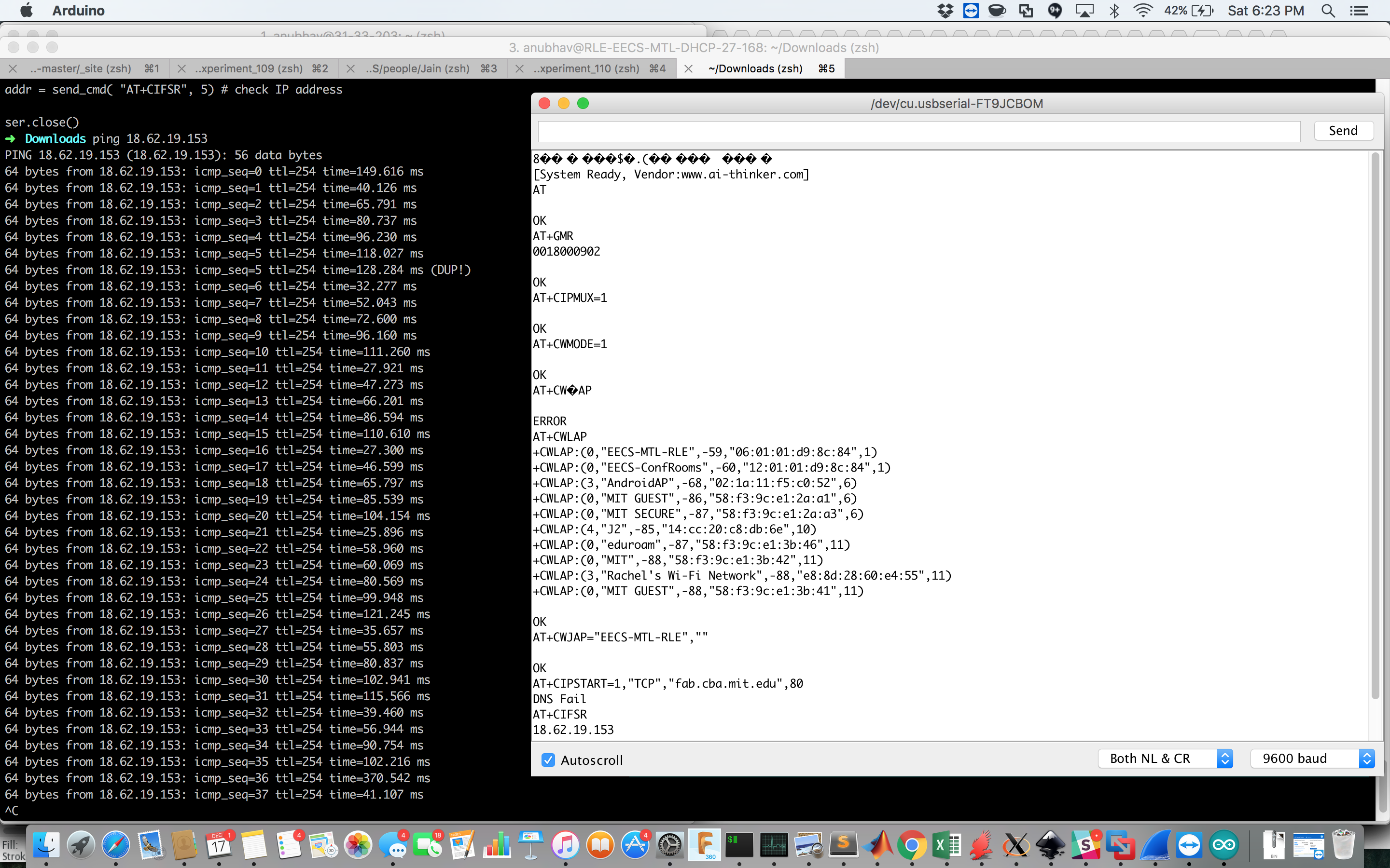
Next, I connected up my board according to what I thought the pin’s should have been. However, I was just getting gibberish back over the terminal - when I typed AT, I wasn’t seeing an OK back from the device.
 .
.
However, I was finally able to find the right baud rate and see that it was resetting itself.
At this poing, I was very confused and unsure what to do. I was able to see data back, and it was mostly coherent English and not garbled, but I wasn’t able to determine what was causing the issue of not letting me talk to the device. After almost giving up, I decided to give reflashing a try.
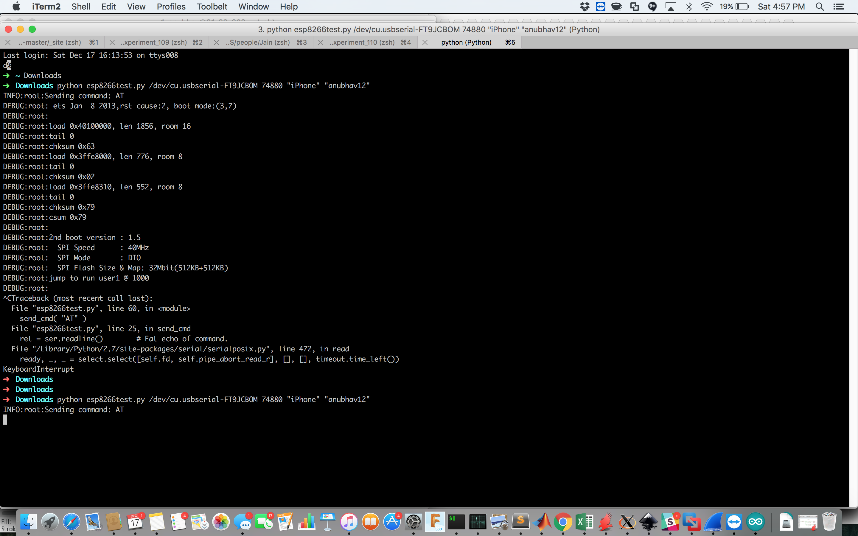
After finding this tutorial from last year’s Fab class, I flashed using esptool.py and the AT 0.9.2 firmware version. After doing this, all the commands succeeded!
Here’s a handy sheet of the commands to interface with the ESP 8266, though there are many libraries available online as well.
At this poing, I was overjoyous and reinvigorated as nothing had seemed to work earlier!
Testing the BME 280 Sensor
To test the BME 280 sensor, I took an Arduino Uno and just hooked it up to my machine. I was hoping to be able to use the Arduino to test I2C communication as someone else in our section had struggled to get it to work and I wanted confirmation the sensor worked before trying to add it to my system.
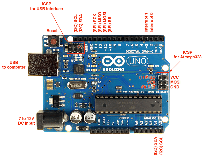
I soldered a few pins onto the BME sensor and then was ready to go. I jumped all the cables to the Arduino, using Analog Pins 4 and 5 for SDA and SCL as seen on the pinout below.
After putting this together, I used the following example sketch to test communication with the BME 280 library:
#include <Adafruit_BME280.h>
//#include <ESP8266WiFi.h>
#include <Wire.h>
#include "cactus_io_BME280_I2C.h"

// Create BME280 object
//BME280_I2C bme; // I2C using address 0x77
BME280_I2C bme(0x76); // I2C using address 0x76

void setup() {
//  Wire.begin(17, 5); // GPIO2, GPIOO -> D4, D3

  Serial.begin(9600);
  Serial.println("Bosch BME280 Pressure - Humidity - Temp Sensor | cactus.io");

  if (!bme.begin()) {
    Serial.println("Could not find a valid BME280 sensor, check wiring!");
    delay(500);
    while (1);
  }

  bme.setTempCal(-1);// Temp was reading high so subtract 1 degree

  Serial.println("Pressure\tHumdity\t\tTemp\ttTemp");
}

void loop() {

  bme.readSensor();

  Serial.print(bme.getPressure_MB()); Serial.print(" mb\t"); // Pressure in millibars
  Serial.print(bme.getHumidity()); Serial.print(" %\t\t");
  Serial.print(bme.getTemperature_C()); Serial.print(" *C\t");
  Serial.print(bme.getTemperature_F()); Serial.println(" *F");

  // Add a 2 second delay.
  delay(2000); //just here to slow down the output.
}
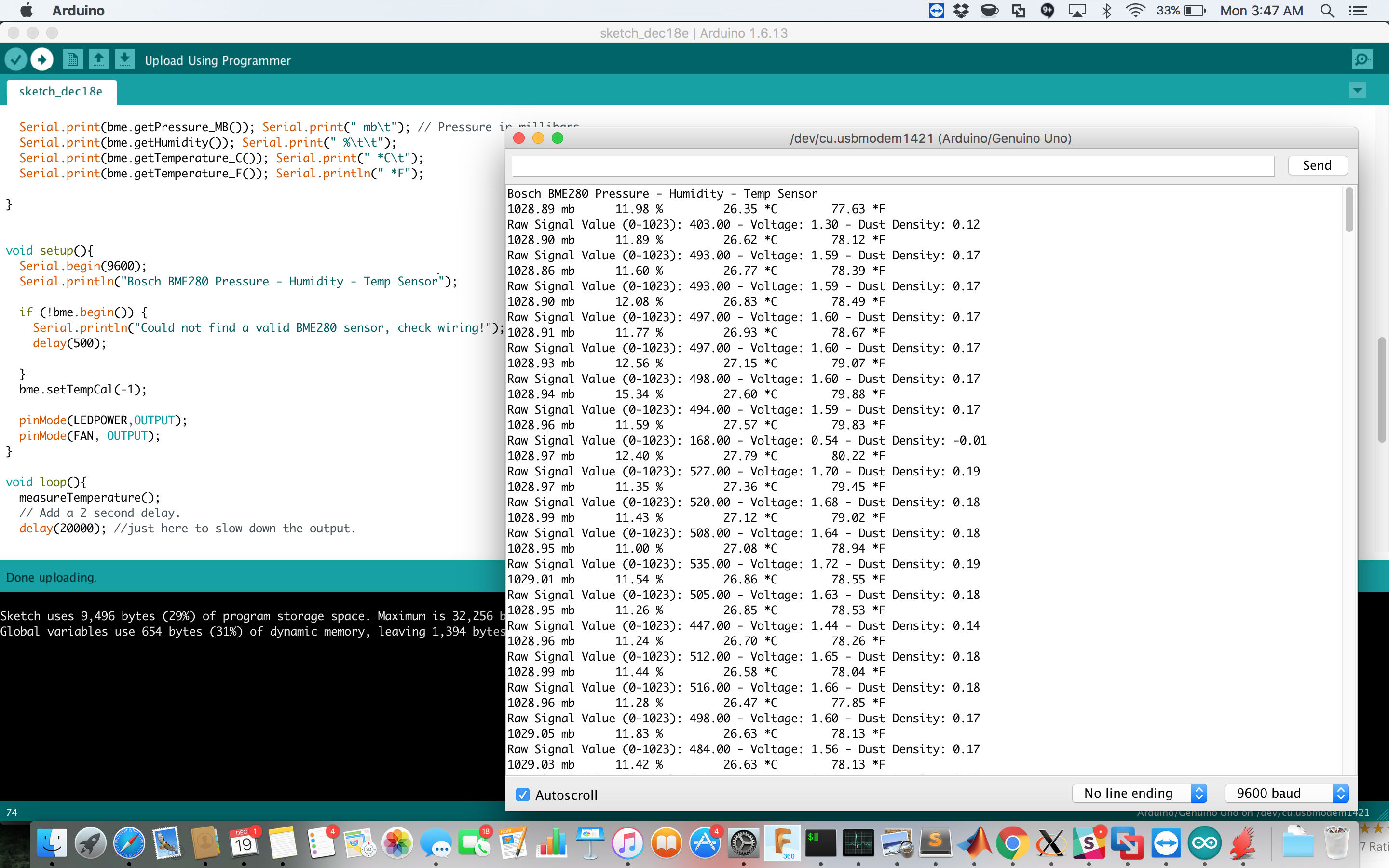
And we had success! I was able to see printouts from the Bosch BME 280 chip and the readings looked reasonable as I tested breathing hot air on it to increase the relative humidity and touched the sensor to increase the temperature.
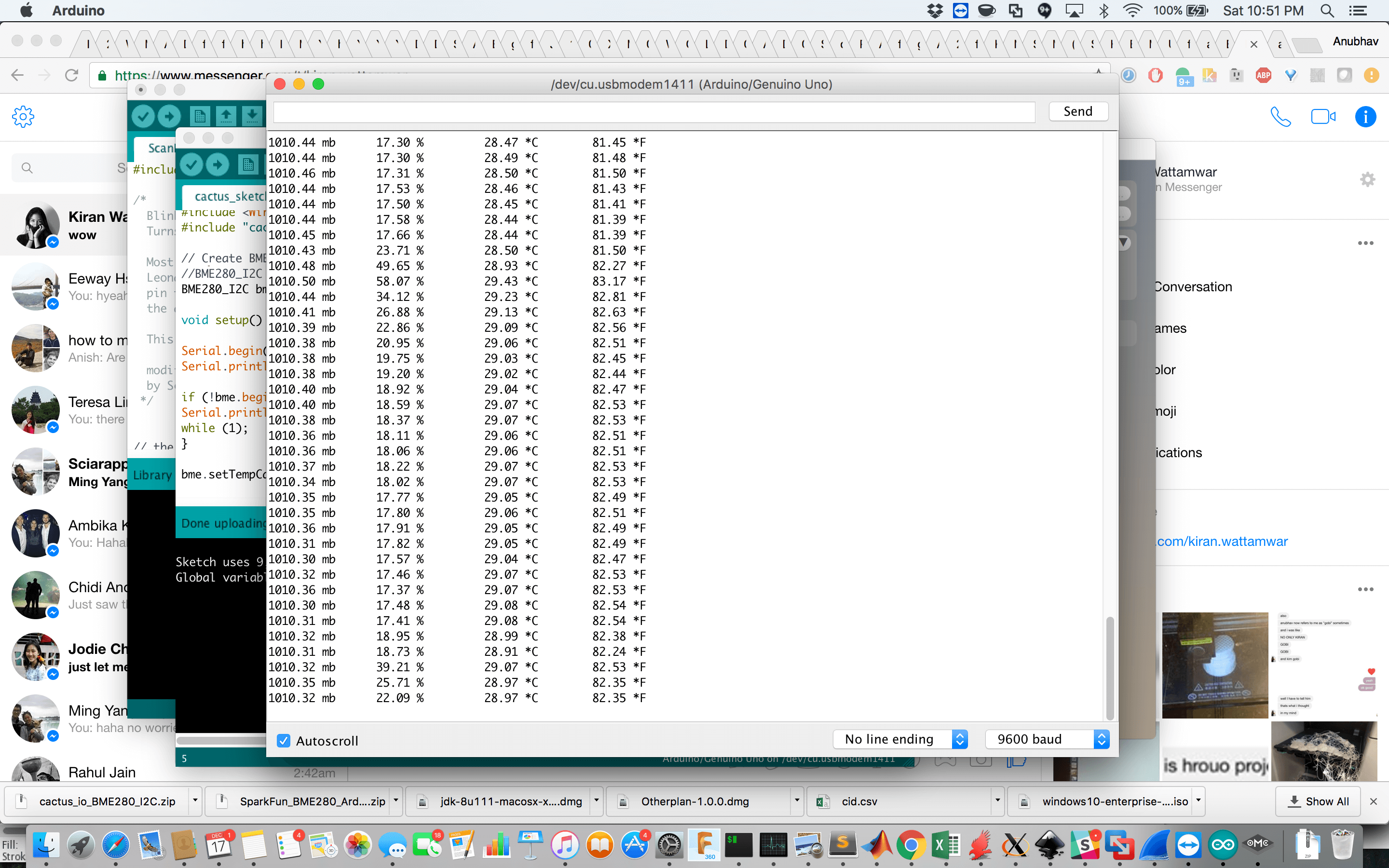
The I2C address for my device was 0x76 but it can also be 0x77.
Integrating the ESP 8266 with the BME 280
As a part of my development process, I now wanted to check that I could talk to the BME 280 and send that data to a server in the cloud to test that the flow of my system worked. This is where things got very challenging. It seemed to be a simple switch to use I2C on the ESP 8266, as I just needed to configure certain pins to work on the I2C protocol. However, no matter how I tried to do this, I was unable to do so.
I got “No I2C Module” found errors, which meant that the 8266 was unable to talk to the BME 280. I kept trying this for the next 6 hours, but then decided that it was time to call it quits and come up with a workaround the next day since it was going to be Sunday and this project was due Tuesday afternoon. I tried to use an I2C scanner that checked all possible addresses on the ESP 8266 but that yielded nothing, as well as just trying example sketches or changing the Arduino sketch to work with the ESP 8266.
Small update: after reading a lot more into I2C over the last few days, I suspect that I would have been able to succesfully do this communication if I had added in pull-up resistors to the I2C inputs. I had assumed I wouldn’t need to do this / the device should still be recognized without it from the ESP 8266 especially since it worked directly with the Arduino, but I think one of the issues is that the Arduino has internal pull up resistors built in that I hadn’t realized initially.
Switching over to using the Arduino Uno
After this, I decided to switch over to using the Arduino Uno to get a MVP working and then to come back and debug this if I had time later. I went on to get the Pollution sensor integrated as I had been able to communicate to the Wi-Fi chip using an FTDI cable, and I knew I could make the Arduino act as my serial interface to the Wi-Fi chip if I wanted.
For the PM 2.5 sensor, I needed a separate board that provided the RC LED circuit as well as gave access to the pins that came out from the sensor and controlled the fan.
I went through 3 iterations of this circuit as I had initially designed it to work with the ESP 8266.
Initial design to have everything on one board:
Second design to work with the Arduino and modularized setup:
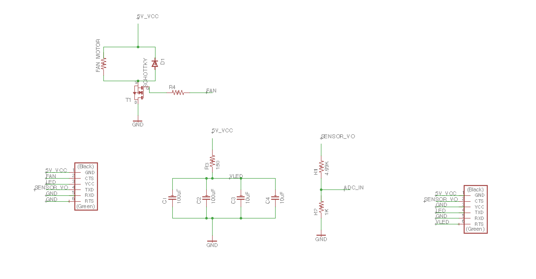
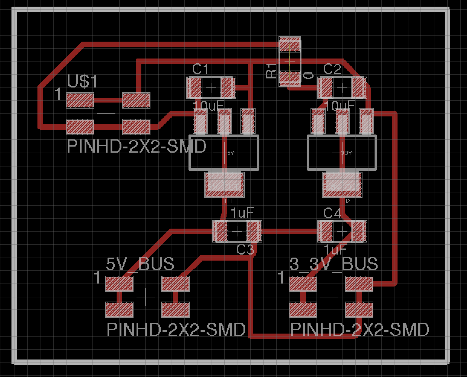
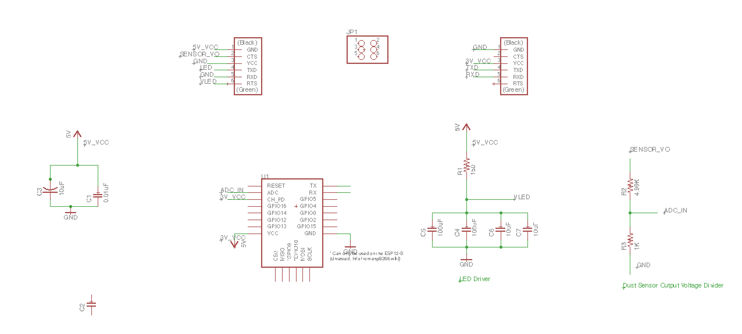
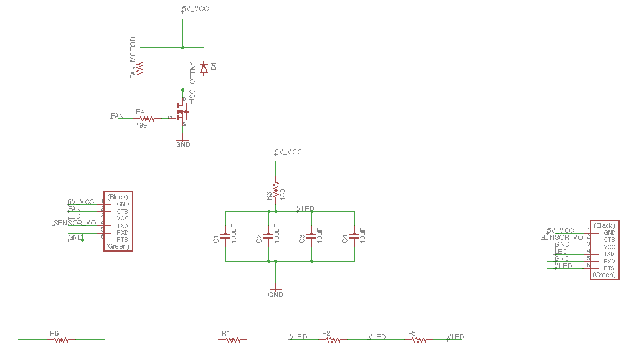
My final schematic removed the voltage divider on the ADC as I didn’t need it anymore and changed the format of the LED control circuit since I could just tie that pin low on the Arduino since the Arduino could handle 5V pins, removing the need for the MOSFET design I had figured out earlier.
Final schematic:
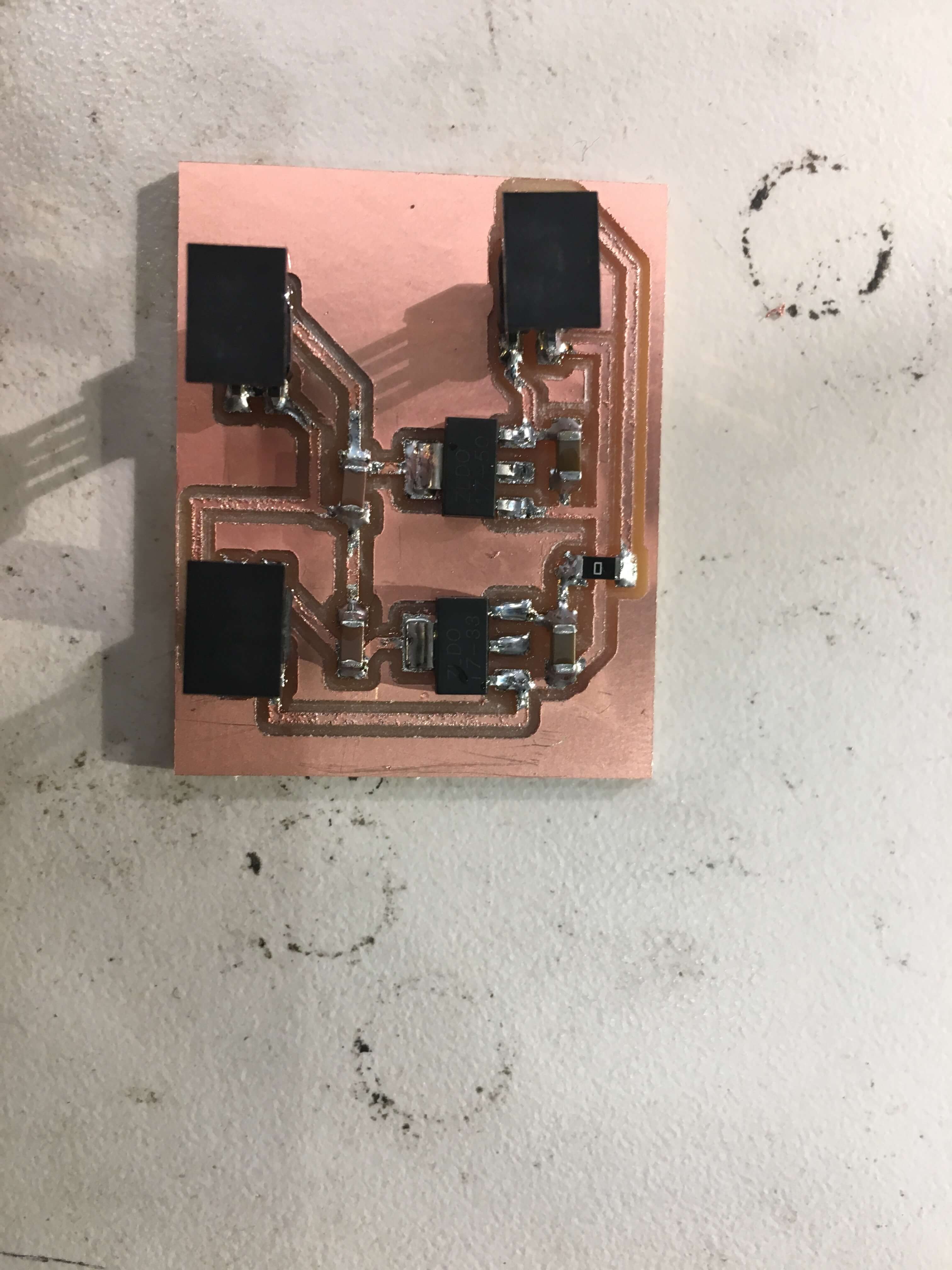
Fabbing out the PM2.5 Circuit
I fabbed this circuit out, and it came out very nicely. I had used 2 FTDI headers to provide control from the Arduino and to also interface with the XHP-6 connector from the PM 2.5 sensor.
Here’s the board fabbed out and components soldered on top:
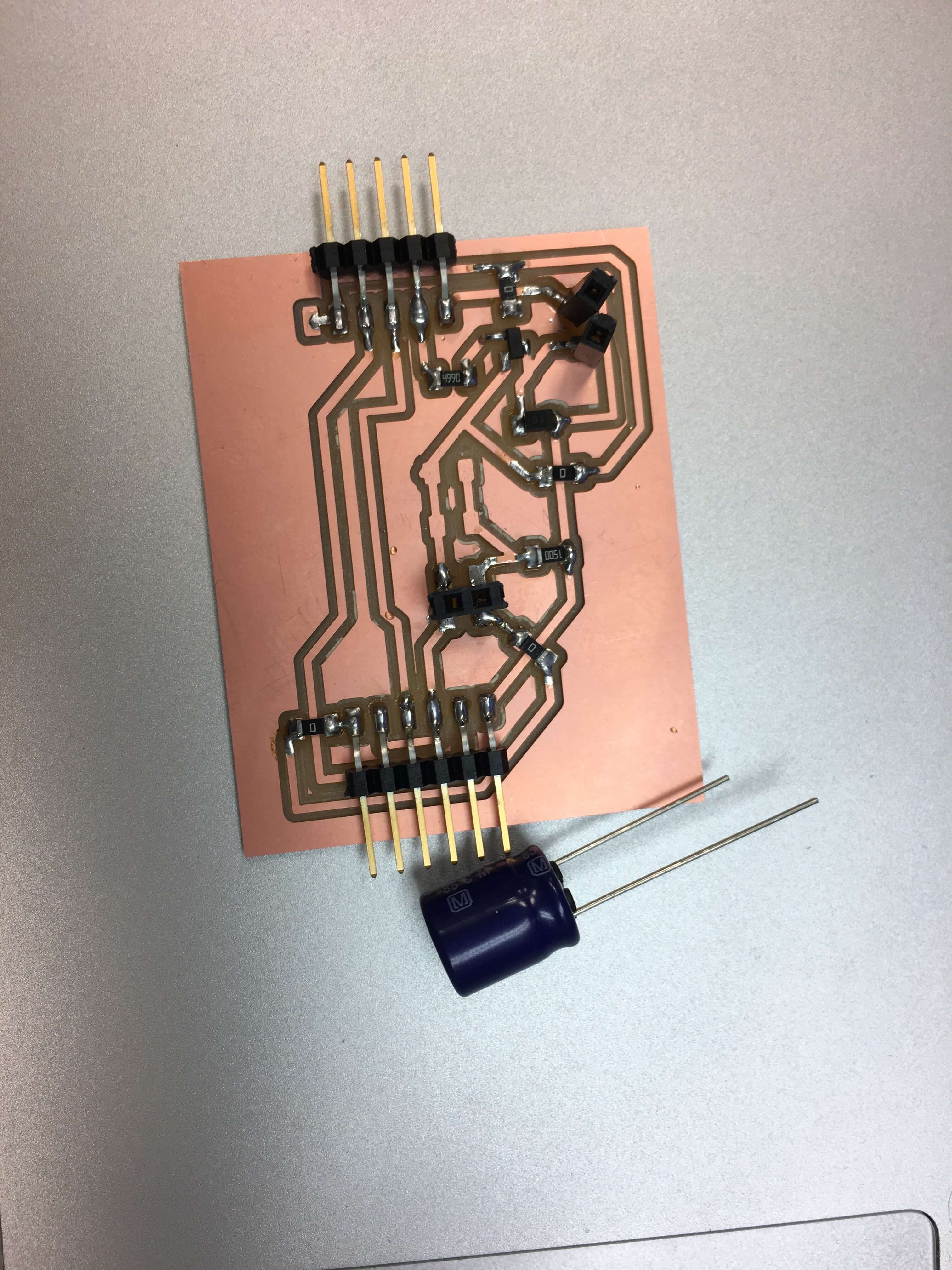
I had to use a 220 uF capacitor in the RC circuit and initially thought that we had 100 uF and 10uF capacitors in stock, so I just put 4 pads and put them in parallel. However, when it came to soldering, I found out that I had read the inventory wrong and that we didn’t have the 220uF in surface mount parts, so I ended up using a through hole polarized capacitor. I was careful about the orientation so as not to blow the capacitor and added it by adding some female pin headers to my board. Luckily, they fit perfectly onto the capacitor pads/traces and everything worked great :)
Once the board was soldered, I just tried connecting it to power and experienced no issues! It was a really good feeling after a long stressful weekend so far.
I was able to modify some of the previously used code to measure pollution sensor data to read the PM 2.5 sensor and get back readings, and went ahead and integrated it with my BME 280 readings, to alternate getting both. The reason I need the BME 280 is because the voltage output on the PM 2.5 sensor changes based on temperature and relative humidity in the air, so I needed to be able to calculate those to get actual concetration readings!
Code to integrate both sensors:
#include <Adafruit_BME280.h>
//#include <ESP8266WiFi.h>
#include <Wire.h>
#include "cactus_io_BME280_I2C.h"

BME280_I2C bme(0x76); // I2C using address 0x76, uses SDA(4) and SCL(5) on Arduino Uno

#define DEBUG 1 // Turn on debug messages
#define FAN 10 // Use Digital Pin 10 to control the Fan
#define SENSOR_IN 1 // Use Analog Pin 1 for ADC
#define LEDPOWER 12 // Use Digital Pin 12 to control LED

int samplingTime = 280; // Sample after 0.28 ms
int deltaTime = 40; // Wait for 0.40ms afterwards before ending pulse
int sleepTime = 9680;

float voMeasured = 0;
float calcVoltage = 0;
float dustDensity = 0;

float curTemperature = 0.0; // Temp in degrees
float curHumidity = 0.0; // Humidity as percentage
float curPressure = 0.0; // Pressure in millibars
float pm25 = 0.0; // PM2.5 Concentration

void fanOn() {
    digitalWrite(FAN, HIGH);
}

void fanOff() {
    digitalWrite(FAN, LOW);
}

void measureTemperatureAndRH() {
  bme.readSensor();

  curPressure = bme.getPressure_MB();
  curHumidity = bme.getHumidity();
  curTemperature = bme.getTemperature_C();
#ifdef DEBUG
  Serial.print(curPressure); Serial.print(" mb\t"); // Pressure in millibars
  Serial.print(curHumidity); Serial.print(" %\t\t");
  Serial.print(curTemperature); Serial.print(" *C\t");
#endif
}

// Todo: Check this.
float voltageToPM25(int vo) {
    float dv, vr, pm25 = 0.0;
    float Vref = 0.0;

    Vref = 5.0;     //When Vcc is connected, A1 has 5V

    vr = (Vref/1.0543)*(0.007143*curTemperature+0.89);  // calib the Vref against temp

    dv = (vo/5) - vr;
    dv = (dv < 0) ? 0 : dv;
    // Formula below from datasheet
    if (curHumidity > 50.0) {
        pm25 = 0.6*(1-0.01467*(curHumidity-50))*dv;
    } else {
        pm25 = 0.6*dv;
    }
    return pm25;
}


int readPM25Sensor() {
    unsigned long d320us, d10ms, t = 0;
    long v = 0;
    int i = 0;

    for (i=0; i<40; i++) {
        t = micros();
        digitalWrite(LEDPOWER,LOW); // power on the LED
        delayMicroseconds(samplingTime);
        v += analogRead(SENSOR_IN); // read the dust sensor voltage

        d320us = 320 + t - micros();
        delayMicroseconds(d320us);
        digitalWrite(LEDPOWER,HIGH);   // turn off LED
        d10ms = 10000 + t - micros();
        delayMicroseconds(d10ms);
    }
#ifdef DEBUG
        Serial.print("d320us = ");
        Serial.println(d320us);
        Serial.print("d10ms = ");
        Serial.println(d10ms);

        Serial.print("Average ");
        Serial.println(v/i);
#endif
    return (v/i);
}


void measureAQI() {
    int v, aqi = 0;
    char sv[128];

    // Turn fan on, delay by 3 seconds and read sensor values.
    fanOn();
    delay(3000);
    v = readPM25Sensor();
    fanOff();

    measureTemperatureAndRH();
    pm25 = voltageToPM25(v);

    //Todo - Convert PM25 concentration to AirQualityIndex using EPA standarfds
    #ifdef DEBUG
    Serial.print("PM 2.5 concentration (ug/m3): ");
    Serial.println(pm25);
    #endif
}


void setup(){
  Serial.begin(9600);
  Serial.println("Using Bosch BME280 Pressure - Humidity - Temp Sensor with Sharp PM2.5 Dust Sensor to measure PM2.5 Concentration :)");

  if (!bme.begin()) {
    Serial.println("Could not find a valid BME280 sensor, check wiring!");
    delay(500);
  }
  bme.setTempCal(-1);

  pinMode(LEDPOWER,OUTPUT);
  digitalWrite(LEDPOWER, HIGH);
  pinMode(FAN, OUTPUT);
  fanOff();
}

void loop(){


  measureTemperatureAndRH();
  // Add a 2 second delay.
  delay(2000);

  measureAQI();

  delay(5000);
}
Here are both of them alternating on the Serial Monitor:
Integrating everything with the Wi-Fi
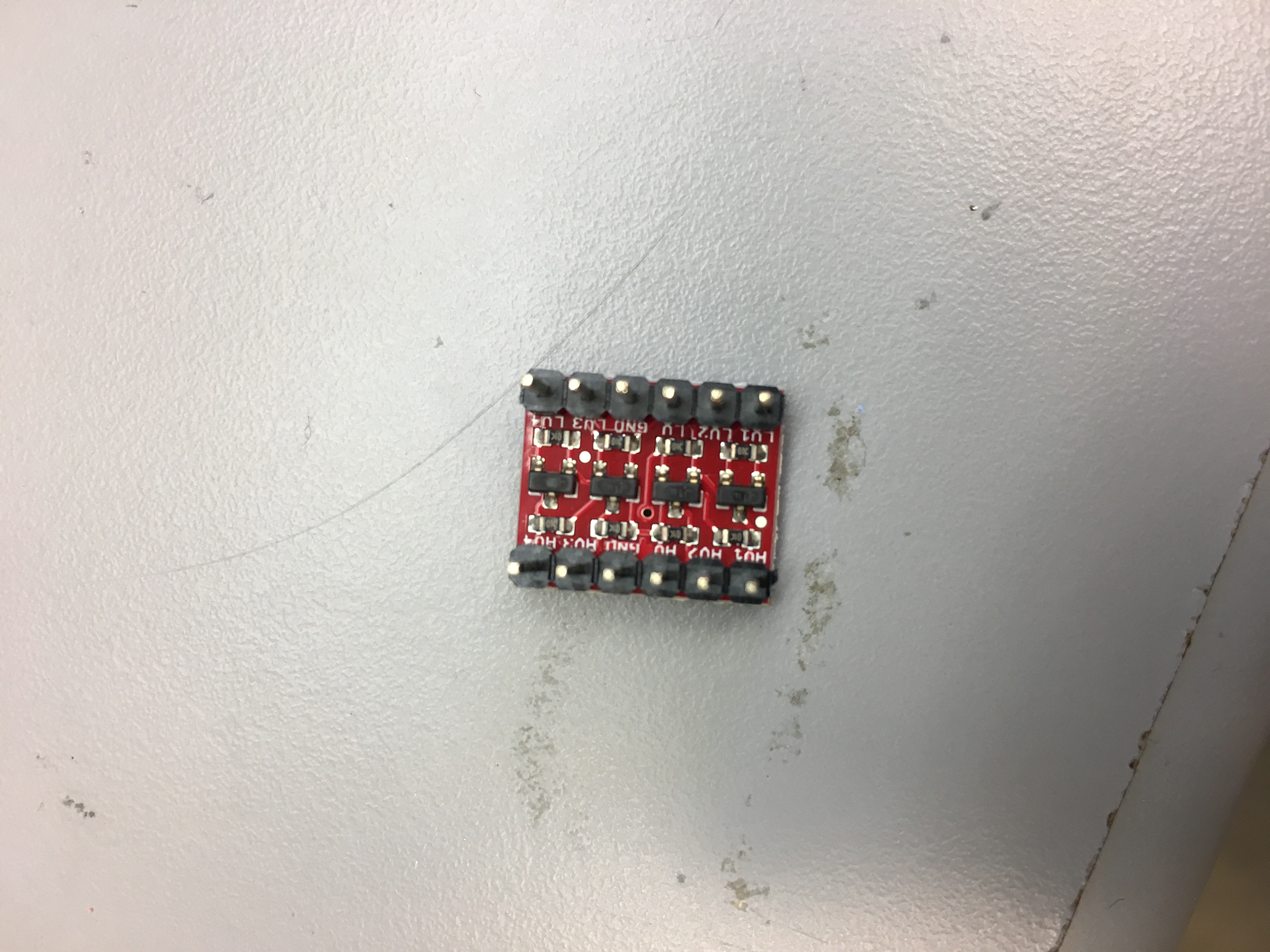
Now that I was able to get all the sensor readings, I needed to integrate it with the Wi-Fi! This proved to be much more difficult than expected - the ESP 8266 only used 3.3V, while the Arduino output 5V. While I made a copy of this schematic for the Sparkfun Bidirectional level shifter, I didn’t want to spend the time fabbing it out as I had a spare of the Sparkfun part that I decided to use initially to get things working.
Here’s the level shifter after I added some straight pins onto it for my jumpers:
Once I did this, I just wired up the RX/TX pins of the Arduino to the TX/RX pins of the ESP8266 and provided the high voltage, low voltage and ground to the level shifter circuit. This worked beautifully as I was able to get the Wi-Fi board to communicate and send requests to my server.
The Wi-Fi integration was also particularly hard because the various libraries to interact with the 8266 wouldn’t always work / might be okay doing SoftwareSerial but fail when I want to program the Arduino to make the 8266 do a specific task.
I finally found this gist that did exactly what I was looking for. It programmed the 8266 to connect to Wi-Fi and do a TCP Get Request on www.google.com. My current plan had been to just do Get Requests to the server with the parameters being the current sensor readings and hacking the server to use this as data input, instead of adding in POST requests to send the data.
Here’s my working code with this Gist - querying my server at a local MIT IP:
   #include <SoftwareSerial.h>
   //use mega Serial 2 for serial monitor; Serial 1 on pins 19 (RX) and 18 (TX);// Serial2 on pins 17 (RX) and 16 (TX), Serial3 on pins 15 (RX) and 14 (TX).
   #define SSID "EECS-MTL-RLE"
   #define PASS ""
   #define DST_IP "128.30.79.122" //my server
   SoftwareSerial Serial2(2,3); // RX, TX
   void setup()
   {
     // Open serial communications and wait for port to open:
     //serial 2 is to esp8266
     Serial2.begin(9600);//9600 (mine), 57600, 115200
     Serial2.setTimeout(1000);

     //serial 0 is to usb
     Serial.begin(115200);


     while(!Serial);
     while(!Serial2);

     //dbgSerial.begin(9600); //can't be faster than 19200 for softserial
     //dbgSerial.println("ESP8266 Demo");
     Serial.println("ESP8266 Demo on Mega2560");

    while(Serial2.available()>0)
    Serial2.read();

     delay(1000);
       //test if the module is ready
     Serial2.println("AT+RST");
     //delay(1000);
     //delay(1000);
     Serial.println("Resetting module");
     Serial2.flush();

     delay(1000);
     //connect to the wifi
     boolean connected=false;
     for(int i=0;i<5;i++)
     {
       if(connectWiFi())
       {
         connected = true;
         break;
       }
     }
     if (!connected){while(1);}
     delay(5000);
     //print the ip addr
     /*
   Serial2.println("AT+CIFSR");
     Serial.println("ip address:");
     while (Serial2.available())
     Serial.write(Serial2.read());

   */
     //set the single connection mode
     Serial2.println("AT+CIPMUX=0");
   }
   void loop()
   {
     String cmd = "AT+CIPSTART=\"TCP\",\"";
     cmd += DST_IP;
     cmd += "\",80";
     Serial2.println(cmd);
     //dbgSerial.println(cmd);
     Serial.println(cmd);
     if(Serial2.find("Error")) return;
//     cmd = "GET / HTTP/1.0\r\n\r\n";
     cmd = "GET /humidity=";
     cmd += millis();
     cmd += ",";
     cmd += "t=";
      cmd += "120,";
      cmd += "pm=";
      cmd += millis();
      cmd += " HTTP/1.0\r\n\r\n";
     Serial2.print("AT+CIPSEND=");
     Serial2.println(cmd.length());
     if(Serial2.find(">"))
     {
       //dbgSerial.print(">");
       Serial.print(">");
       }else
       {
         Serial2.println("AT+CIPCLOSE");
         //dbgSerial.println("connect timeout");
         Serial.println("connect timeout");
         delay(1000);
         return;
       }
       Serial2.print(cmd);
       delay(2000);
       //Serial.find("+IPD");
       while (Serial2.available())
       {
         char c = Serial2.read();
         //dbgSerial.write(c);
         Serial.write(c);
         //if(c=='\r') dbgSerial.print('\n');
         if(c=='\r') Serial.print('\n');
       }
       //dbgSerial.println("====");
       Serial.println("====");
       delay(1000);
     }
     boolean connectWiFi()
     {
       Serial2.println("AT+CWMODE=1");
       String cmd="AT+CWJAP=\"";
       cmd+=SSID;
       cmd+="\",\"";
       cmd+=PASS;
       cmd+="\"";
       //dbgSerial.println(cmd);
       Serial2.println(cmd);
       Serial.println(cmd);
       delay(2000);
       if(Serial2.find("OK"))
       {
         //dbgSerial.println("OK, Connected to WiFi.");
         Serial.println("OK, Connected to WiFi.");
         return true;
         }else
         {
           //dbgSerial.println("Can not connect to the WiFi.");
           Serial.println("Can not connect to the WiFi.");
           return false;
         }
       }
One big modification is to define Serial2 as a SoftwareSerial port. I think Serial2 might be defined for other boards that support multiple Serial connections, but that doesn’t exist for the Uno and thus this code will crash if you don’t add in the line to define it as a SoftwareSerial port.
Another issue with this circuit was that I initially hadn’t provided the Arduino with access to the RST pin on the ESP 8266 and it seemed to get bricked frequently, especially when I might power cycle the Arduino but not the 8266 since it was running off of battery power. I was initially manually resetting that pin whenever it failed to connect to Wi-Fi, but I ended up jumping it into one of the Arduino digital pins to provide it software access to pull down the RESET pin and unbrick the board. I ended up actually just resetting the Wi-Fi everytime it failed to do a TCP request to my server, pulling down the RESET pin and then re-connecting. This seemed to solve any of my issues associated with sending data to the server - I know it takes a lot more energy but it was a workaround to get the system working.
Integration with the BME280 and PM2.5 Sensors
Now, for the final step, I just needed to take the data I was getting earlier and add in the Wi-Fi configuration code. This was a relatively painless process and below is the final code with a video of the system running together.
#include <Adafruit_BME280.h>
//#include <ESP8266WiFi.h>
#include <Wire.h>
#include "cactus_io_BME280_I2C.h"
#include <SoftwareSerial.h>

// Definitions for sensors
BME280_I2C bme(0x76); // I2C using address 0x76, uses SDA(4) and SCL(5) on Arduino Uno

#define DEBUG 1 // Turn on debug messages
#define FAN 10 // Use Digital Pin 10 to control the Fan
#define SENSOR_IN 1 // Use Analog Pin 1 for ADC
#define LEDPOWER 12 // Use Digital Pin 12 to control LED

// Definitions for Wi-Fi
#define WIFIRESET 4
#define SSID "EECS-MTL-RLE"
#define PASS ""
#define DST_IP "128.30.79.122"
SoftwareSerial Serial2(2,3); // RX, TX

int samplingTime = 280; // Sample after 0.28 ms
int deltaTime = 40; // Wait for 0.40ms afterwards before ending pulse
int sleepTime = 9680;

float voMeasured = 0;
float calcVoltage = 0;
float dustDensity = 0;

float curTemperature = 0.0; // Temp in degrees
float curHumidity = 0.0; // Humidity as percentage
float curPressure = 0.0; // Pressure in millibars
float pm25 = 0.0; // PM2.5 Concentration

void fanOn() {
    digitalWrite(FAN, HIGH);
}

void fanOff() {
    digitalWrite(FAN, LOW);
}

void measureTemperatureAndRH() {
  bme.readSensor();

  curPressure = bme.getPressure_MB();
  curHumidity = bme.getHumidity();
  curTemperature = bme.getTemperature_C();
#ifdef DEBUG
  Serial.print(curPressure); Serial.print(" mb\t"); // Pressure in millibars
  Serial.print(curHumidity); Serial.print(" %\t\t");
  Serial.print(curTemperature); Serial.print(" *C\t");
#endif
}

void resetWifiPin() {
  digitalWrite(WIFIRESET, LOW);
  delay(500);
  digitalWrite(WIFIRESET, HIGH);

}

// Todo: Check this.
float voltageToPM25(int vo) {
    float dv, vr, pm25 = 0.0;
    float Vref = 0.0;

    Vref = 5.0;     //When Vcc is connected, A1 has 5V

    vr = (Vref/1.0543)*(0.007143*curTemperature+0.89);  // calib the Vref against temp

    dv = (vo/5) - vr;
    dv = (dv < 0) ? 0 : dv;
    // Formula below from datasheet
    if (curHumidity > 50.0) {
        pm25 = 0.6*(1-0.01467*(curHumidity-50))*dv;
    } else {
        pm25 = 0.6*dv;
    }
    return pm25;
}

void setupWifi() {

  Serial2.begin(9600);
  Serial2.setTimeout(1000);

   while(!Serial2);

   while(Serial2.available()>0)
    Serial2.read();

  pinMode(WIFIRESET,OUTPUT);
  resetWifiPin();

   delay(1000);
   //test if the module is ready
   Serial2.println("AT+RST");
   //delay(1000);
   //delay(1000);
   Serial.println("Resetting module");
   Serial2.flush();

   delay(1000);
     //connect to the wifi
     boolean connected=false;
     for(int i=0;i<5;i++)
     {
       if(connectWiFi()) {
         connected = true;
         break;
       } else {
        resetWifiPin();
       }

     }
   if (!connected){while(1);}
     delay(5000);

      Serial2.println("AT+CIFSR");
     Serial.println("ip address:");
     while (Serial2.available())
     Serial.write(Serial2.read());

     //set the single connection mode
     Serial2.println("AT+CIPMUX=0");
}


int readPM25Sensor() {
    unsigned long d320us, d10ms, t = 0;
    long v = 0;
    int i = 0;

    for (i=0; i<40; i++) {
        t = micros();
        digitalWrite(LEDPOWER,LOW); // power on the LED
        delayMicroseconds(samplingTime);
        v += analogRead(SENSOR_IN); // read the dust sensor voltage

        d320us = 320 + t - micros();
        delayMicroseconds(d320us);
        digitalWrite(LEDPOWER,HIGH);   // turn off LED
        d10ms = 10000 + t - micros();
        delayMicroseconds(d10ms);
    }
#ifdef DEBUG
        Serial.print("d320us = ");
        Serial.println(d320us);
        Serial.print("d10ms = ");
        Serial.println(d10ms);

        Serial.print("Average ");
        Serial.println(v/i);
#endif
    return (v/i);
}

int sendWifi(float humidity, float temperature, float pm25) {
  String cmd = "AT+CIPSTART=\"TCP\",\"";
     cmd += DST_IP;
     cmd += "\",80";
     Serial2.println(cmd);
     //dbgSerial.println(cmd);
     Serial.println(cmd);
     if(Serial2.find("Error")) return;
//     cmd = "GET / HTTP/1.0\r\n\r\n";
     cmd = "GET /humidity=";
     cmd += humidity;
     cmd += ",";
     cmd += "t=";
      cmd += temperature;
      cmd += ",pm=";
      cmd += pm25;
      cmd += " HTTP/1.0\r\n\r\n";
     Serial2.print("AT+CIPSEND=");
     Serial2.println(cmd.length());
     if(Serial2.find(">"))
     {
       //dbgSerial.print(">");
       Serial.print(">");
       }else
       {
         Serial2.println("AT+CIPCLOSE");
         //dbgSerial.println("connect timeout");
         Serial.println("connect timeout");
         delay(1000);
         connectWiFi();
         return;
       }
       Serial2.print(cmd);
       delay(2000);
       //Serial.find("+IPD");
       while (Serial2.available())
       {
         char c = Serial2.read();
         //dbgSerial.write(c);
         Serial.write(c);
         //if(c=='\r') dbgSerial.print('\n');
         if(c=='\r') Serial.print('\n');
       }
       //dbgSerial.println("====");
       Serial.println("====");
       delay(1000);
     }
 boolean connectWiFi()
 {
     resetWifiPin();
   Serial2.println("AT+CWMODE=1");
   String cmd="AT+CWJAP=\"";
   cmd+=SSID;
   cmd+="\",\"";
   cmd+=PASS;
   cmd+="\"";
   //dbgSerial.println(cmd);
   Serial2.println(cmd);
   Serial.println(cmd);
   delay(2000);
   if(Serial2.find("OK"))
   {
     //dbgSerial.println("OK, Connected to WiFi.");
     Serial.println("OK, Connected to WiFi.");
     return true;
     }else
     {
       //dbgSerial.println("Can not connect to the WiFi.");
       Serial.println("Can not connect to the WiFi.");
       return false;
     }


}


void measureAQI() {
    int v, aqi = 0;
    char sv[128];

    // Turn fan on, delay by 3 seconds and read sensor values.
    fanOn();
    delay(3000);
    v = readPM25Sensor();
    fanOff();

    measureTemperatureAndRH();
    pm25 = voltageToPM25(v);

    //Todo - Convert PM25 concentration to AirQualityIndex using EPA standarfds
    #ifdef DEBUG
    Serial.print("PM 2.5 concentration (ug/m3): ");
    Serial.println(pm25);
    sendWifi(curHumidity, curTemperature, pm25);
    #endif
//    aqi = calculateAirQualityIndex(pm25);
//    sprintf(sv, "{\"value\":%d,\"pm25\":%.3f,\"aqi\":%d,\"temperature\":%.2f,\"humidity\":%.2f}", v, pm25, aqi, tp, rh);
//    client.publish("sensornet/aqi/AQI01/allvalues",sv);
}


void setup(){

  Serial.begin(9600);
  setupWifi();
  Serial.println("Using Bosch BME280 Pressure - Humidity - Temp Sensor with Sharp PM2.5 Dust Sensor to measure PM2.5 Concentration :)");

  if (!bme.begin()) {
    Serial.println("Could not find a valid BME280 sensor, check wiring!");
    delay(500);
  }
  bme.setTempCal(-1);

  pinMode(LEDPOWER,OUTPUT);
  digitalWrite(LEDPOWER, HIGH);
  pinMode(FAN, OUTPUT);
  fanOff();
}

void loop(){


  measureTemperatureAndRH();
  // Add a 2 second delay.
  delay(2000);

  measureAQI();
  // 0 - 3.3V mapped to 0 - 1023 integer values
  // recover voltage
//  calcVoltage = voMeasured * (3.3 / 1024);

  // linear eqaution taken from http://www.howmuchsnow.com/arduino/airquality/
  // Chris Nafis (c) 2012
//  dustDensity = 0.17 * calcVoltage - 0.1;

//  Serial.print("Raw Signal Value (0-1023): ");
//  Serial.print(voMeasured);
//
//  Serial.print(" - Voltage: ");
//  Serial.print(calcVoltage);
//
//  Serial.print(" - Dust Density: ");
//  Serial.println(dustDensity);
//
  delay(5000);
}
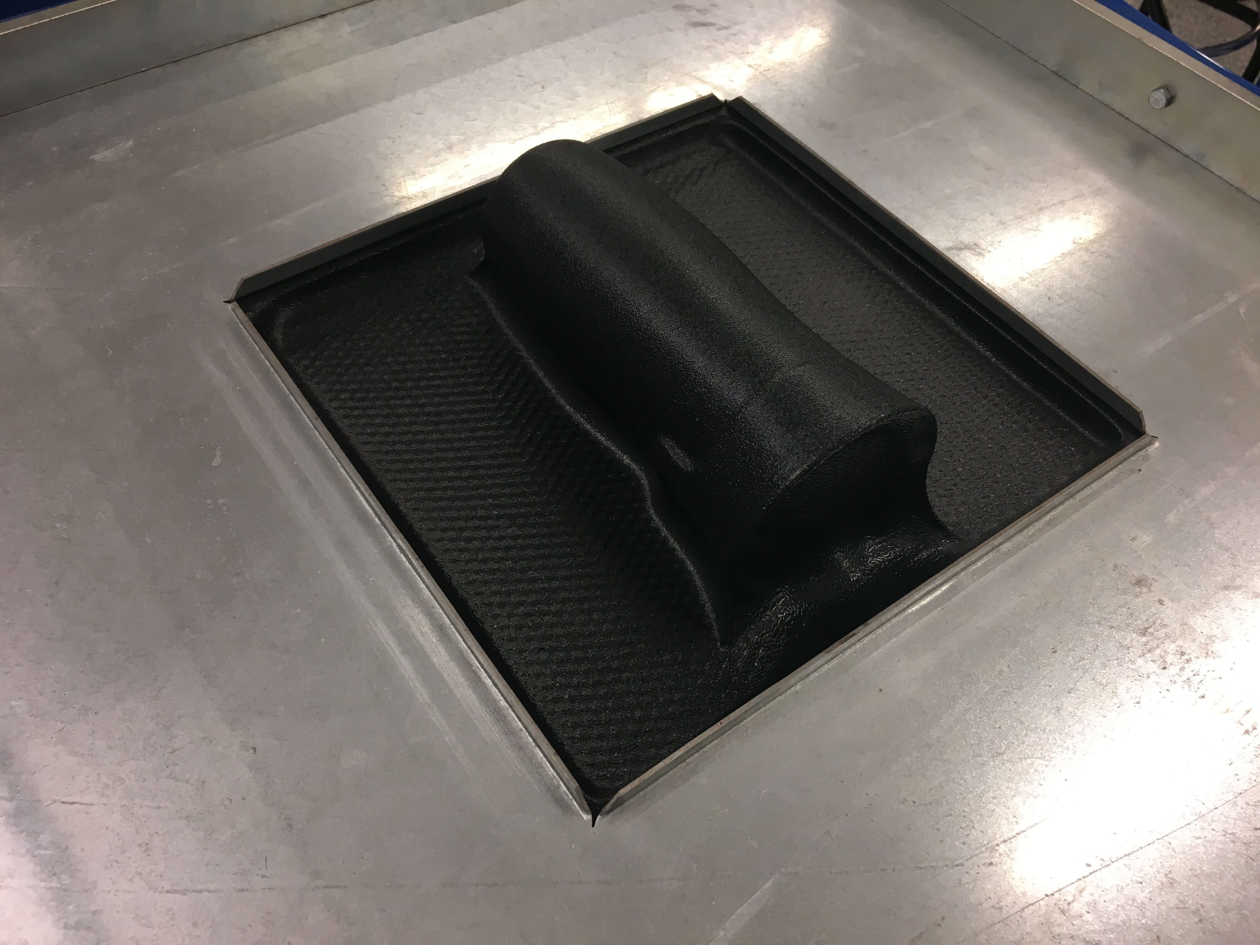
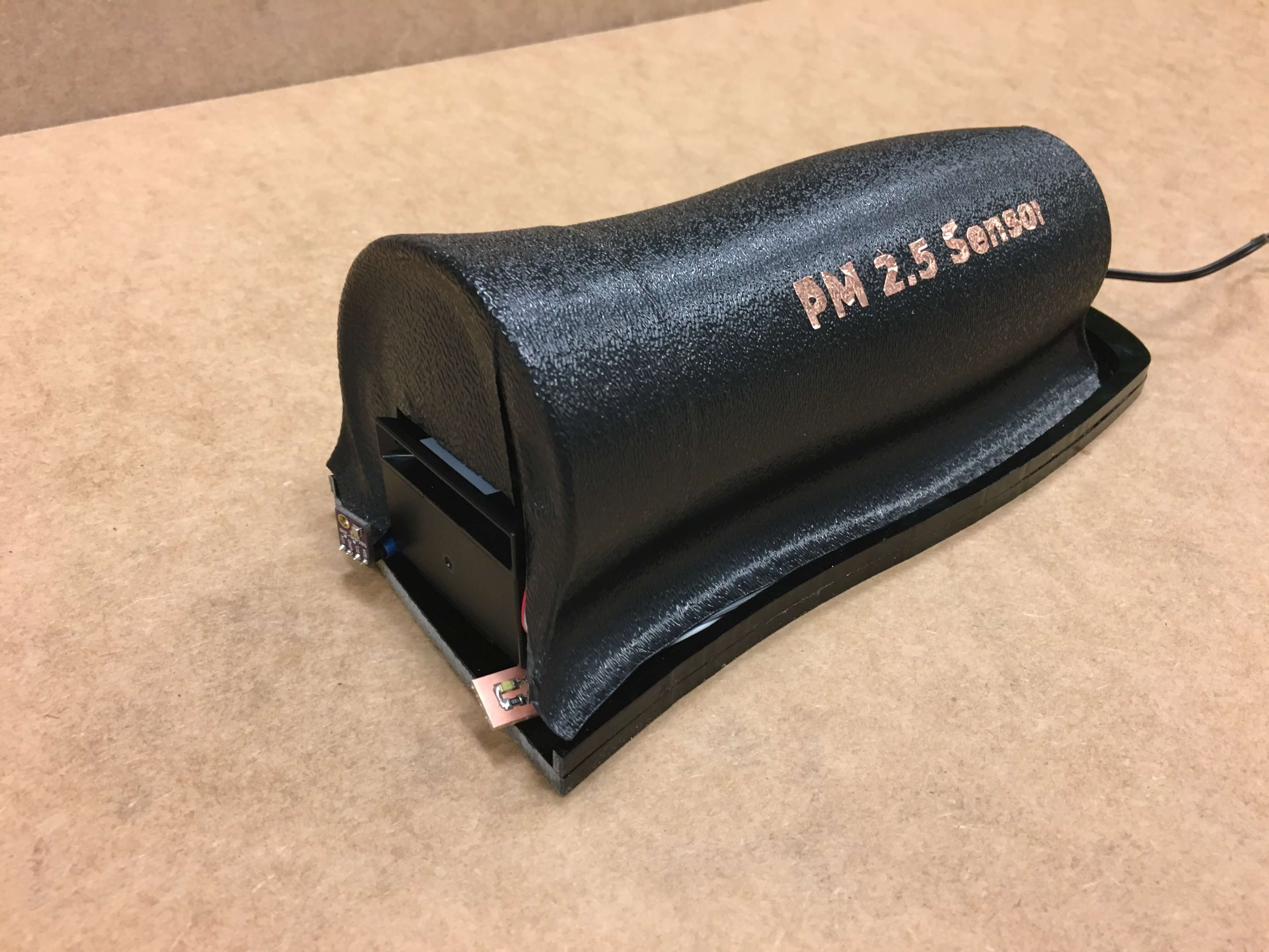
Creating the enclosure
I created the enclosure by thermoforming around a thermos I had. The thermos was the right shape and size of the sensor I was looking for, especially as the curvy sides to it resembled wind in the air, and thus was an interesting design to work with to make the final housing.
One of the thermoforms failed - it popped because the plastic became too soft. The next one was successful and below you’ll see the thermoformed plastic and then everything combined together.
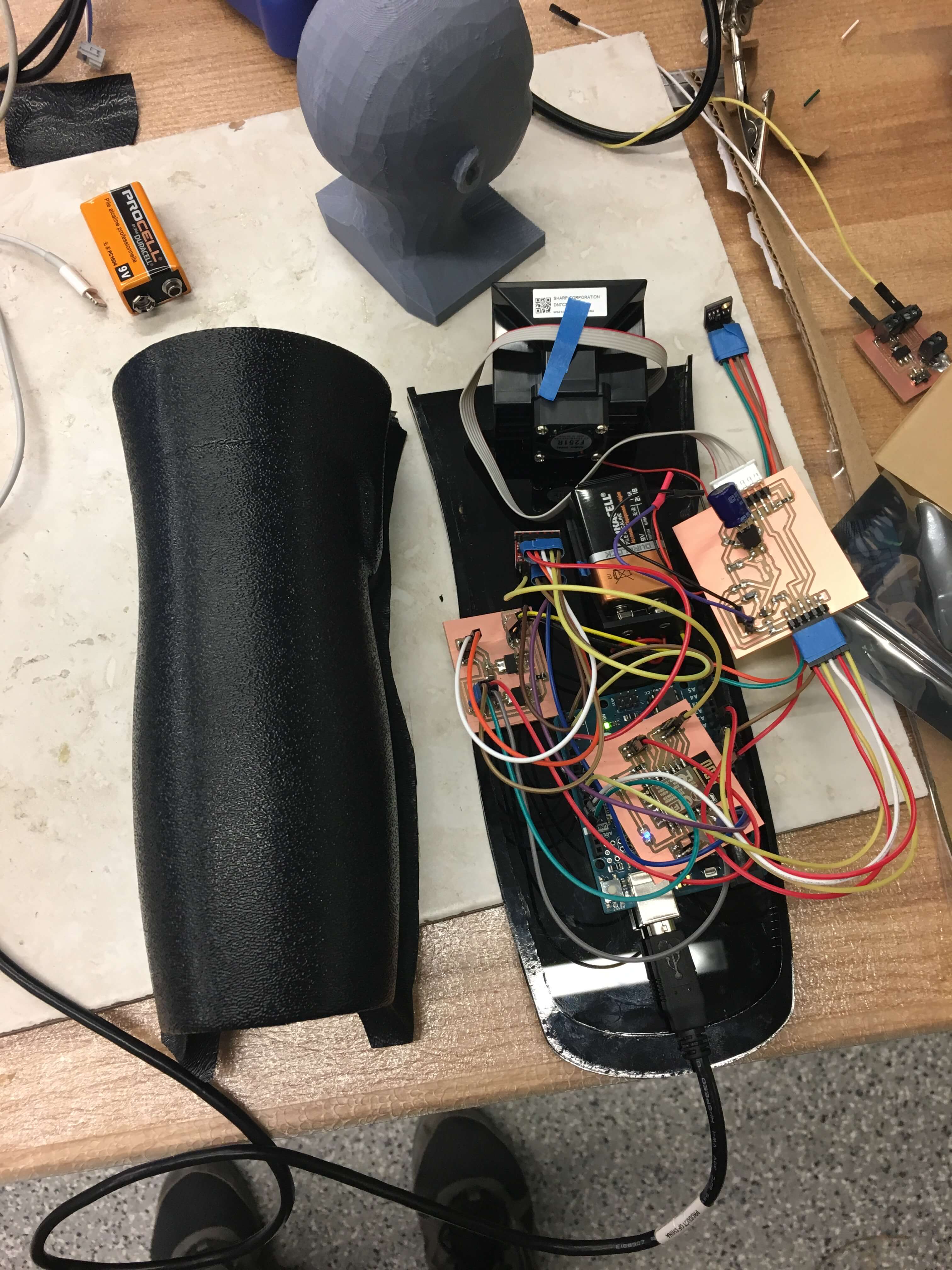
I also tried thermoforming an ABS plastic but didn’t like the white outside texture, and thus didn’t use it. However, the white ABS was very nice to work with since it was so soft and easy to cut with scissors.
After this, I started to put all my components into my laser cut acrylic base. I chose black acrylic and measured out the width of the thermoformed plastic, creating a two layer piece so that the plastic could snuggly fit inside of the second layer, while not looking like it was being held in place by that. Below, you’ll see the final sensor with all the electronics inside and the case on the left too.
Vinyl Cutting
I vinyl cut letters onto the enclosure as can be seen below. I hadn’t yet been able to do vinyl cutting and wanted to give it a shot. I tried white vinyl tape but that wasn’t very successful as the letters wouldn’t peel off at all and so I switched back to the copper tape. While the copper wasn’t perfect, I certainly had more success and was able to copy the letters onto masking tape to transfer to my theroformed cover. I had to do a bit of repair but that wasn’t too bad with scissors and some fine tweezers.
Final Product
Here’s the final product - it all works!
Things I learned and Future Steps
- Add LEDs to your board frequently - they help to be able to debug what’s happening and understand if the board is doing anything at all, plus they look super cool :) These are especially useful on any data lines, as then they will turn on / off automatically to show data going over the wire
- Minimize the load on the battery - I ended up going through about a 9V battery every few hours. I was using it to provide power to various parts of my circuit (temperature sensor, Wi-Fi, etc) and to use the additional pins I had added there to provide more ground/power pins. This resulted in the batteries dying very quickly, which I could have saved by only using the battery for the ESP 8266. I could have also changed my circuit to take a power supply and generate the power board from there - however, I had initially wanted these to be lowcost and cheap sensors that would be easy to deploy so I didn’t want to worry about input power.
Future Steps:
- Redesign power board - the current power board is useful but ends up killing the 9V battery. Plus, it also causes a mess of wires - it would be great to redesign this!
- Create an Arduino shield - once I had decided to use the Arduino Uno to make my setup, it would have been prudent to create an Arduino shield that plugged into all the pinouts on the Arduino and only had the ones we wanted connected. This would have resulted in the ability to have 1-2 boards instead of the 4 I have now. It would’ve also reduced the wire count and the mess caused by them, improving communication between the modules as well.
- Testing the accuracy of the pollution detection by using regular smoke, car exhaust and comparing against a market pollution sensor
- Redesign housing and try to use the ESP8266 or otherwise another AVR to replace the Arduino
- Look into doing a deployment in India :)
- Redesign the circuit to use less power so it can be deployed for longer
- Try to work without an Arduino but maybe with the 328P or another Atmel processor - this would bring the cost done and definitely let me redesign the enclosure as everything would hopefully be smaller.
Anyways, this semester has been tons of fun in general - got to learn how to do so many things and feel just a lot more confident in my building opportunities overall!